EP1517776B1 - Verfahren zur herstellung einer drosselklappe in einem durchgehenden drosselklappenstutzen durch spritzgiessen von kunststoff - Google Patents
Verfahren zur herstellung einer drosselklappe in einem durchgehenden drosselklappenstutzen durch spritzgiessen von kunststoff Download PDFInfo
- Publication number
- EP1517776B1 EP1517776B1 EP03740094A EP03740094A EP1517776B1 EP 1517776 B1 EP1517776 B1 EP 1517776B1 EP 03740094 A EP03740094 A EP 03740094A EP 03740094 A EP03740094 A EP 03740094A EP 1517776 B1 EP1517776 B1 EP 1517776B1
- Authority
- EP
- European Patent Office
- Prior art keywords
- throttle valve
- plastic
- valve body
- die
- throttle
- Prior art date
- Legal status (The legal status is an assumption and is not a legal conclusion. Google has not performed a legal analysis and makes no representation as to the accuracy of the status listed.)
- Expired - Lifetime
Links
- 239000004033 plastic Substances 0.000 title claims abstract description 57
- 238000004519 manufacturing process Methods 0.000 title claims description 5
- 238000001746 injection moulding Methods 0.000 title description 2
- 230000002093 peripheral effect Effects 0.000 claims abstract description 10
- 238000000034 method Methods 0.000 claims description 14
- 230000000295 complement effect Effects 0.000 claims description 10
- 230000015572 biosynthetic process Effects 0.000 claims description 5
- 229920000265 Polyparaphenylene Polymers 0.000 claims 3
- -1 polyphenylene Polymers 0.000 claims 3
- UCKMPCXJQFINFW-UHFFFAOYSA-N Sulphide Chemical compound [S-2] UCKMPCXJQFINFW-UHFFFAOYSA-N 0.000 claims 2
- 150000003568 thioethers Chemical class 0.000 claims 1
- 239000000463 material Substances 0.000 abstract description 4
- 239000004734 Polyphenylene sulfide Substances 0.000 description 7
- 229920000069 polyphenylene sulfide Polymers 0.000 description 7
- 238000002347 injection Methods 0.000 description 3
- 239000007924 injection Substances 0.000 description 3
- 238000005266 casting Methods 0.000 description 2
- 229910000831 Steel Inorganic materials 0.000 description 1
- XAGFODPZIPBFFR-UHFFFAOYSA-N aluminium Chemical compound [Al] XAGFODPZIPBFFR-UHFFFAOYSA-N 0.000 description 1
- 229910052782 aluminium Inorganic materials 0.000 description 1
- 238000001816 cooling Methods 0.000 description 1
- 238000004512 die casting Methods 0.000 description 1
- 238000010348 incorporation Methods 0.000 description 1
- 230000003993 interaction Effects 0.000 description 1
- 238000012805 post-processing Methods 0.000 description 1
- 239000010959 steel Substances 0.000 description 1
- 230000007704 transition Effects 0.000 description 1
Images


Classifications
-
- F—MECHANICAL ENGINEERING; LIGHTING; HEATING; WEAPONS; BLASTING
- F16—ENGINEERING ELEMENTS AND UNITS; GENERAL MEASURES FOR PRODUCING AND MAINTAINING EFFECTIVE FUNCTIONING OF MACHINES OR INSTALLATIONS; THERMAL INSULATION IN GENERAL
- F16K—VALVES; TAPS; COCKS; ACTUATING-FLOATS; DEVICES FOR VENTING OR AERATING
- F16K27/00—Construction of housing; Use of materials therefor
- F16K27/02—Construction of housing; Use of materials therefor of lift valves
- F16K27/0209—Check valves or pivoted valves
- F16K27/0218—Butterfly valves
-
- B—PERFORMING OPERATIONS; TRANSPORTING
- B29—WORKING OF PLASTICS; WORKING OF SUBSTANCES IN A PLASTIC STATE IN GENERAL
- B29C—SHAPING OR JOINING OF PLASTICS; SHAPING OF MATERIAL IN A PLASTIC STATE, NOT OTHERWISE PROVIDED FOR; AFTER-TREATMENT OF THE SHAPED PRODUCTS, e.g. REPAIRING
- B29C45/00—Injection moulding, i.e. forcing the required volume of moulding material through a nozzle into a closed mould; Apparatus therefor
- B29C45/0017—Injection moulding, i.e. forcing the required volume of moulding material through a nozzle into a closed mould; Apparatus therefor moulding interconnected elements which are movable with respect to one another, e.g. chains or hinges
- B29C2045/002—Injection moulding, i.e. forcing the required volume of moulding material through a nozzle into a closed mould; Apparatus therefor moulding interconnected elements which are movable with respect to one another, e.g. chains or hinges using shrinkage
-
- B—PERFORMING OPERATIONS; TRANSPORTING
- B29—WORKING OF PLASTICS; WORKING OF SUBSTANCES IN A PLASTIC STATE IN GENERAL
- B29C—SHAPING OR JOINING OF PLASTICS; SHAPING OF MATERIAL IN A PLASTIC STATE, NOT OTHERWISE PROVIDED FOR; AFTER-TREATMENT OF THE SHAPED PRODUCTS, e.g. REPAIRING
- B29C45/00—Injection moulding, i.e. forcing the required volume of moulding material through a nozzle into a closed mould; Apparatus therefor
- B29C45/16—Making multilayered or multicoloured articles
- B29C2045/1601—Making multilayered or multicoloured articles the injected materials not being adhered or bonded to each other
-
- B—PERFORMING OPERATIONS; TRANSPORTING
- B29—WORKING OF PLASTICS; WORKING OF SUBSTANCES IN A PLASTIC STATE IN GENERAL
- B29C—SHAPING OR JOINING OF PLASTICS; SHAPING OF MATERIAL IN A PLASTIC STATE, NOT OTHERWISE PROVIDED FOR; AFTER-TREATMENT OF THE SHAPED PRODUCTS, e.g. REPAIRING
- B29C45/00—Injection moulding, i.e. forcing the required volume of moulding material through a nozzle into a closed mould; Apparatus therefor
- B29C45/14—Injection moulding, i.e. forcing the required volume of moulding material through a nozzle into a closed mould; Apparatus therefor incorporating preformed parts or layers, e.g. injection moulding around inserts or for coating articles
- B29C45/14598—Coating tubular articles
- B29C45/14622—Lining the inner or outer surface of tubular articles
-
- B—PERFORMING OPERATIONS; TRANSPORTING
- B29—WORKING OF PLASTICS; WORKING OF SUBSTANCES IN A PLASTIC STATE IN GENERAL
- B29C—SHAPING OR JOINING OF PLASTICS; SHAPING OF MATERIAL IN A PLASTIC STATE, NOT OTHERWISE PROVIDED FOR; AFTER-TREATMENT OF THE SHAPED PRODUCTS, e.g. REPAIRING
- B29C45/00—Injection moulding, i.e. forcing the required volume of moulding material through a nozzle into a closed mould; Apparatus therefor
- B29C45/16—Making multilayered or multicoloured articles
- B29C45/1671—Making multilayered or multicoloured articles with an insert
-
- B—PERFORMING OPERATIONS; TRANSPORTING
- B29—WORKING OF PLASTICS; WORKING OF SUBSTANCES IN A PLASTIC STATE IN GENERAL
- B29K—INDEXING SCHEME ASSOCIATED WITH SUBCLASSES B29B, B29C OR B29D, RELATING TO MOULDING MATERIALS OR TO MATERIALS FOR MOULDS, REINFORCEMENTS, FILLERS OR PREFORMED PARTS, e.g. INSERTS
- B29K2081/00—Use of polymers having sulfur, with or without nitrogen, oxygen or carbon only, in the main chain, as moulding material
- B29K2081/04—Polysulfides, e.g. PPS, i.e. polyphenylene sulfide or derivatives thereof
-
- B—PERFORMING OPERATIONS; TRANSPORTING
- B29—WORKING OF PLASTICS; WORKING OF SUBSTANCES IN A PLASTIC STATE IN GENERAL
- B29K—INDEXING SCHEME ASSOCIATED WITH SUBCLASSES B29B, B29C OR B29D, RELATING TO MOULDING MATERIALS OR TO MATERIALS FOR MOULDS, REINFORCEMENTS, FILLERS OR PREFORMED PARTS, e.g. INSERTS
- B29K2705/00—Use of metals, their alloys or their compounds, for preformed parts, e.g. for inserts
-
- B—PERFORMING OPERATIONS; TRANSPORTING
- B29—WORKING OF PLASTICS; WORKING OF SUBSTANCES IN A PLASTIC STATE IN GENERAL
- B29L—INDEXING SCHEME ASSOCIATED WITH SUBCLASS B29C, RELATING TO PARTICULAR ARTICLES
- B29L2031/00—Other particular articles
- B29L2031/748—Machines or parts thereof not otherwise provided for
- B29L2031/7506—Valves
Definitions
- the present invention relates to a method according to the preamble of claim 1.
- Throttles in throttle body are known.
- a throttle body is described with a tubular housing in which a throttle valve is mounted on a throttle shaft, which is rotatably supported transversely to the longitudinal axis of the tubular housing at their free ends by recesses in the housing wall.
- the arrangement of throttle valves in the throttle body is often disadvantageous that due to partially extremely small leakage specifications with high precision and surface quality must be worked.
- the casting material of which the throttle body is made, and the casting quality must have a high quality standard.
- the throttle valve is usually stamped from a sheet and turned very finely with great precision, with very low tolerances must be met.
- the invention has for its object to provide a method for producing a throttle in a throttle body, in which the tolerance requirements for the gap between the throttle and throttle body are easier to comply.
- the object underlying the invention is achieved by a method of the type described above, wherein the at least one breakthrough is closed before entering the second plastic complementary to the throttle body, wherein the non-existent at the site of at least one breakthrough projection is added in that after removal of the first punch and the second punch from the throttle body, at least one throttle shaft perpendicular to the longitudinal axis of the throttle body is inserted through the aperture and the throttle is fixed to the at least one throttle shaft.
- a circumferential, for example, annular groove is incorporated, then from both sides a third punch and a fourth punch be retracted into these throttle body, which are complementary to each other and form a cylindrical cavity in the retracted state in the region of the annular groove having a circumferential projection to the center of the throttle body, then laterally through the opening of the first plastic in molten form into the cylindrical cavity entered and there for curing and formation of a plastic insert with the running to the center of the throttle body, circumferential projection is brought.
- the throttle body for example, consist of aluminum die casting.
- the in the throttle body incorporated circumferential, annular groove may be bounded on one side or two sides parallel to the longitudinal axis of the throttle body.
- the throttle body may also be made entirely of the first plastic.
- the formation of the plastic insert 10 can be dispensed with in a particularly advantageous manner.
- the first stamp, the second stamp, the third stamp and the fourth stamp are made of steel.
- the third punch and the fourth punch are complementary to each other. This means that they function together functionally and together form the cylindrical cavity, wherein the peripheral projection of this cylindrical cavity is formed by their abutting state in the retracted end faces by local material removal.
- the circumferential projection may be annular.
- the first plastic differs from the second plastic in its shrinkability during the cooling phase. This ensures that forms a slight gap between the manufactured throttle and the throttle body, so that the throttle valve can not connect to the throttle body or plastic insert. Before introducing the second plastic, the at least one opening of the throttle body is closed in a manner complementary to the throttle body or plastic insert.
- the at least one throttle valve shaft to be arranged after the formation of the throttle flap will generally be designed in one piece or in two parts. If it is designed in two parts, then the connection of the throttle valve with the two-part throttle shaft via a connecting element, which is configured strichschalenfbrmig, for example via a screw or rivet connection.
- the input of the second plastic in the throttle body is usually via a centrally extending through the first punch bore.
- a preferred embodiment of the invention is that the circumferential projection of the throttle body is not formed continuously at the same distance from the edges of the throttle body and the maximum angle ⁇ between the perpendicular to the longitudinal axis of the throttle body and the direct connection of two directly opposite areas of the circumferential projection It is between 7 ° and 8 °. In this way, the generally desired oblique position of the throttle in the continuous throttle body is achieved in a simple manner.
- the end faces of the third punch and the fourth punch are designed to be complementary running obliquely.
- polyphenylene sulfides having different linear expansion coefficients are used as the first plastic and as the second plastic. These polyphenylene sulfides are particularly suitable due to their shrinkage behavior for the production of the throttle valve.
- PPS polyphenylene sulfide
- PPS polyphenylene sulfide
- a further preferred embodiment of the invention is that the throttle valve is attached to the at least one throttle shaft by means of lasers. It is advantageous that the throttle shaft can be made in one piece, while the attachment can be done effectively without additional elements such as screws or rivets.
- Fig. 1 thus shows the state of the method according to the incorporation of the circumferential groove. Claim 2.
- the third punch 4 and the fourth punch 5 are designed to be complementary. This means that their faces abut each other in the retracted state.
- the throttle body 2 has a circumferential, annular groove 3, which is bounded on one side by the throttle body 2 parallel to the longitudinal axis of the throttle body 2.
- the third punch 4 and the fourth punch 5 form in the region of the annular groove 3 a cylindrical cavity 6, in the subsequent third step laterally through at least one opening (not shown) of the throttle body 2, a molten first. Plastic is entered. This then completely fills the cylindrical first cavity 6, which has a circumferential projection 7 to the center of the throttle body 2.
- the throttle body 2 is shown with the third punch 4 and the fourth punch 5 in cross section.
- the first plastic is already entered into the cylindrical cavity (not shown) and cured there, wherein a plastic insert 10 is formed.
- the third punch 4 and the fourth punch 5 are removed from the throttle body 2 in the direction of the arrow.
- the plastic insert then remains in the throttle body 2 and has a running towards the center of the throttle body 2, circumferential projection 13.
- a plastic insert 10 is shown simplified with the circumferential projection 13 together with the throttle valve 1.
- the plastic insert 10 has a first opening 10 'and a second opening 10' ', which are closed before the second injection to form the throttle valve (not shown) complementary to the plastic insert.
- Fig. 4 the third punch 4 and the fourth punch 5 are shown in the throttle body 2 in almost retracted state three-dimensional.
- the throttle body 2 has two openings B, 9, through which a first supply 19 and a second supply 20 are retracted for the first plastic. They simultaneously serve to vent the cylindrical cavity 6 (not shown) during the first injection process.
- the first plastic is introduced via the first supply 19 or via the second supply 20 to form the plastic insert 10.
- the third punch 4 and the fourth punch 5 are removed from the throttle body.
- Fig. 5 is an exploded view of FIG. 4 is shown. In this case, only the circumferential projection 13th the plastic insert 10 has been shown running continuously.
- Fig. 6 the throttle body 2 is shown three-dimensionally in the retracted state together with the first punch 11 and the second punch 12.
- the first supply and the second supply for the first plastic have now been moved out of the device and have been replaced by a first plug 21 and a second plug 22 which close the openings 8, 9 of the throttle body 2 complementary to the plastic insert 10 .
- a throttle valve-shaped cavity 14 (not shown) is formed.
- a molten second plastic is entered through the first punch 11 in the throttle valve-shaped cavity 14 and there brought to the curing and formation of the throttle valve 1.
- the input of the second plastic into the interior of the throttle body 2 takes place through a centrally located in the first punch 11 bore 11 ', After curing of the throttle valve (not shown), the first punch 11 and the second punch 12 are moved out of the throttle body.
- FIG. 7 shows an exploded view according to FIG. 6 with a connecting element 23.
- a two-piece throttle shaft 15, 16 is perpendicular to the longitudinal axis of the throttle body 2 introduced through the throttle body 2 and the plastic insert 10 and the throttle valve 1 attached to the two-piece throttle shaft 15, 16.
- the two-part throttle valve shaft 15, 16 is thereby fixed via the connecting element 23.
- the actual connection takes place in a particularly advantageous manner by lasers.
- Fig. 8a) de top view of the plastic insert 10 with the throttle valve 1 and the cross section according to section A - A is shown schematically and simplified.
- the circumferential projection 13 of the plastic insert 10 does not have the same distance to the edges of the plastic insert 10 throughout.
- the maximum angle ⁇ between the perpendicular to the longitudinal axis of the throttle body 2 (not shown) and the direct connection of two directly opposite regions 17, 18 of the circumferential projection 13 is between 7 ° and 8 °. This usually corresponds to the desired inclination of the throttle valve 1 in the throttle body.
Landscapes
- Engineering & Computer Science (AREA)
- General Engineering & Computer Science (AREA)
- Mechanical Engineering (AREA)
- Manufacturing & Machinery (AREA)
- Lift Valve (AREA)
- Injection Moulding Of Plastics Or The Like (AREA)
Abstract
Description
- Die vorliegende Erfindung betrifft ein Verfahren nach dem Oberbegriff des Anspruchs 1.
- Drosselklappen in Drosselklappestutzen sind bekannt. In der DE 195 12 729 A1 wird ein Drosselklappenstutzen mit einem rohrartigen Gehäuse beschrieben, in dem eine Drosselklappe auf einer Drosselklappenwelle befestigt ist, die quer zur Längsachse des rohrartigen Gehäuses an ihren freien Enden durch Ausnehmungen in der Gehäusewand durchführend drehbar gelagert ist. Bei der Anordnung von Drosselklappen in Drosselklappenstutzen ist oftmals nachteilig, dass aufgrund von teilweise extrem kleinen Leckage-Vorgaben mit hoher Präzision und Oberflächengüte gearbeitet werden muss. Dabei müssen das Gussmaterial, aus dem der Drosselklappenstutzen besteht, und die Gussqualität einen hohen Qualitätsstandard haben. Die Drosselklappe wird dabei in der Regel aus einem Blech gestanzt und mit großem Präzisionsaufwand feinst gedreht, wobei sehr geringe Toleranzen eingehalten werden müssen.
- In der WO 97 04259 A und der FR-A-2 667 601 werden Verfahren der eingangs erwähnten Art beschrieben, in dem bei der gemeinsamen Herstellung von Drosselklappe und Drosselklappenstutzen mittels Zwei-Komponenten-Spritzguß jeweils Kunststoffzapfen an die Drosselklappe angeformt werden. Dabei ergibt sich ein kritischer Übergangsbereich zwischen dem Umfang der Drosselklappe und den Kunststoffzapfen, in dem die geforderten sehr geringen Toleranzen für den Spalt zwischen Drosselklappe und Drosselklappenstutzen schwerlich eingehalten werden können.
- Demgemäß liegt der Erfindung die Aufgabe zugrunde, ein Verfahren zur Herstellung einer Drosselklappe in einem Drosselklappenstutzen zu schaffen, bei dem die Toleranzanforderungen an das Spaltmaß zwischen Drosselklappe und Drosselklappenstutzen leichter einzuhalten sind.
- Die der Erfindung zugrunde liegende Aufgabe wird durch ein Verfahren der eingangs beschriebenen Art gelöst, bei dem der mindestens eine Durchbruch vor dem Eingeben des zweiten Kunststoffes komplementär zu dem Drosselklappenstutzen verschlossen wird, wobei der an der Stelle des mindestens einen Durchbruchs nicht vorhandene umlaufende Vorsprung ergänzt wird, nach dem Entfernen des ersten Stempels und des zweiten Stempels aus dem Drosselklappenstutzen mindestens eine Drosselklappenwelle senkrecht zur Längsachse des Drosselklappenstutzens durch den Durchbruch eingebracht und die Drosselklappe an der mindestens einen Drosselklappenwelle befestigt wird.
- In einer besonders bevorzugten Ausführungsform der Erfindung ist vorgesehen, daß in einem vorangehenden Verfahrensschritt in einem durchgehenden Drosselklappenstutzen, der bereits mit dem mindestens einen Durchbruch versehen ist, eine umlaufende, beispielsweise ringförmige Nut eingearbeitet wird, anschließend von beiden Seiten ein dritter Stempel und ein vierter Stempel in diesen Drosselklappenstutzen eingefahren werden, die zueinander komplementär gestaltet sind und im eingefahrenen Zustand im Bereich der ringförmigen Nut einen zylindrischen Hohlraum bilden, der zur Mitte des Drosselklappenstutzens einen umlaufenden Vorsprung aufweist, anschließend seitlich durch den Durchbruch der erste Kunststoff in aufgeschmolzener Form in den zylindrischen Hohlraum eingegeben und dort zur Aushärtung und Bildung eines Kunststoffeinsatzes mit dem zur Mitte des Drosselklappenstutzens verlaufenden, umlaufenden Vorsprung gebracht wird.
- Der Drosselklappenstutzen kann beispielsweise aus Aludruckguss bestehen. Die in den Drosselklappenstutzen eingearbeitete umlaufende, ringförmige Nut kann einseitig oder zweiseitig parallel zur Längsachse des Drosselklappenstutzens begrenzt sein.
- Der Drosselklappenstutzen kann auch vollständig aus dem ersten Kunststoff gefertigt sein. In diesem Fall kann in besonders vorteilhafter Weise auf die Bildung des Kunststoffeinsatzes 10 verzichtet werden.
- Der erste Stempel, der zweite Stempel, der dritte Stempel sowie der vierte Stempel bestehen aus Stahl. Der dritte Stempel und der vierte Stempel sind zueinander komplementär gestaltet. Das bedeutet, sie wirken funktionell zusammen und bilden gemeinsam den zylindrischen Hohlraum, wobei der umlaufende Vorsprung dieses zylindrischen Hohlraums durch ihre im eingefahrenen Zustand anliegenden Stirnflächen durch dortige Materialwegnahme gebildet wird. Der umlaufende Vorsprung kann ringförmig sein. Der erste Kunststoff unterscheidet sich vom zweiten Kunststoff durch sein Schrumpfungsvermögen während der Abkühlungsphase. Dadurch wird erreicht, dass sich zwischen der hergestellten Drosselklappe und dem Drosselklappenstutzen ein geringfügiger Spalt bildet, so dass die Drosselklappe sich nicht mit dem Drosselklappenstutzen bzw. Kunststoffeinsatz verbinden kann. Vor dem Einbringen des zweiten Kunststoffs wird der mindestens eine Durchbruch des Drosselklappenstutzens komplementär zum Drosselklappenstutzen bzw. Kunststoffeinsatz verschlossen. Dabei werden Stopfen in die Öffnungen eingefahren, die auch im im Bereich der Öffnungen ggf. den zur Mitte des Drosselklappenstutzens verlaufenden, umlaufenden Vorsprung des Kunststoffeinsatzes bzw. des Drosselklappenstutzens, der an der Stelle der Öffnungen ggf. nicht mehr vorhanden ist, ergänzen. Die nach der Bildung der Drosselklappe anzuordnende mindestens eine Drosselklappenwelle wird in der Regel einteilig oder zweiteilig ausgestaltet sein. Ist sie zweiteilig ausgestaltet, so erfolgt die Verbindung der Drosselklappe mit der zweiteiligen Drosselklappenwelle über ein Verbindungselement, das halbschalenfbrmig ausgestaltet ist, beispielsweise über eine Schraub- oder Nietverbindung. Die Eingabe des zweiten Kunststoffs in den Drosselklappenstutzen erfolgt in der Regel über eine mittig durch den ersten Stempel verlaufende Bohrung.
- Es hat sich in überraschender Weise gezeigt, dass bei dem Verfahren zur Herstellung einer Drosselklappe in einem durchgehenden Drosselklappenstutzen keinerlei Drehvorgänge erforderlich sind, bei denen die Einstellung von geringen Toleranzen erfolgt. Das technische Zusammenspiel zwischen Drosselklappe und Kunststoffeinsatz im Drosselklappenstutzen wird alleine durch die zwei Spritzvorgänge im durchgehenden Drosselklappenstutzen realisiert, so dass aufwendige Nachbearbeitungsschritte entfallen können.
- Eine bevorzugte Ausgestaltung der Erfindung besteht darin, dass der umlaufende Vorsprung des Drosselklappenstutzens nicht durchgehend im gleichen Abstand zu den Kanten des Drosselklappenstutzens gebildet wird und der maximale Winkel α zwischen der Senkrechten zur Längsachse des Drosselklappenstutzens und der direkten Verbindung zweier direkt einander gegenüberliegender Bereiche des umlaufenden Vorsprungs dabei zwischen 7° und 8° liegt. Auf diese Weise wird die in der Regel gewünschte schräge Position der Drosselklappe im durchgehenden Drosselklappenstutzen auf einfache Weise erreicht. Die Stirnflächen des dritten Stempels und des vierten Stempels sind dabei komplementär schräg verlaufend ausgebildet.
- Gemäß einer weiteren bevorzugten Ausgestaltung der Erfindung werden als erster Kunststoff und als zweiter Kunststoff Polyphenylensulfide (PPS) mit unterschiedlichen linearen Ausdehnungskoeffizienten eingesetzt. Diese Polyphenylensulfide eignen sich in besonderem Maße aufgrund ihres Schrumpfverhaltens zur Herstellung der Drosselklappe.
- Nach einer weiteren Ausgestaltung der Erfindung ist vorgesehen, daß als erster Kunststoff ein Polyphenylensulfid (PPS) mit einem linearen Ausdehnungskoeffizienten zwischen 90 und 250 °C von 36 · 10-6 und als zweiter Kunststoff ein Polyphenylensulfid (PPS) mit einem linearen Ausdehnungskoeffizienten zwischen 90 und 200 °C von 46 · 10-6 eingesetzt wird. Für den Einsatzzweck sind diese beiden Kunststoffarten in besonders vorteilhafter Weise geeignet
- Eine weitere bevorzugte Ausgestaltung der Erfindung besteht darin, dass die Drosselklappe an der mindestens einen Drosselklappenwelle durch Lasern befestigt wird. Dabei ist vorteilhaft, dass die Drosselklappenwelle einteilig ausgeführt werden kann, wobei gleichzeitig die Befestigung ohne zusätzliche Elemente wie Schrauben oder Nieten wirkungsvoll erfolgen kann.
- Die Erfindung wird nachfolgend anhand der Zeichnung (Fig. 1 bis Fig. 7, 8a), b)) naher und beispielhaft erläutert.
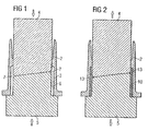
- Fig. 1 zeigt den Drosselklappenstutzen mit dem gebildeten zylindrischen Hohlraum im Querschnitt.
- Fig. 2 zeigt den Drosselklappenstutzen mit dem gebildeten Kunststoffeinsatz im Querschnitt.
- Fig. 3 zeigt die dreidimensionale Darstellung eines Kunststoffeinsatzes zusammen mit der Drosselklappe.
- Fig. 4 zeigt die dreidimensionale Darstellung des dritten Stempels und des vierten Stempels in fast eingefahrenem Zustand im Drosselklappenstutzen.
- Fig. 5 zeigt eine Explosionsdarstellung gem. Fig. 4.
- Fig. 6 zeigt eine dreidimensionale Darstellung des ersten und des zweiten Stempels im Drosselklappenstutzen im eingefahrenen Zustand.
- Fig. 7 zeigt eine Explosionsdarstellung der Anordnung gem. Fig. 6 mit einem Verbindungselement.
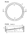
- Fig. 8a), b)zeigt die Draufsicht auf den Kunststoffeinsatz sowie den Kunststoffeinsatz im Querschnitt gem. Schnitt A - A.
- In Fig. 1 sind der Drosselklappenstutzen 2, der dritte Stempel 4 und der vierte Stempel 5, die bereits in den Drosselklappenstutzen 2 in Pfeilrichtung vollständig eingefahren sind, im Querschnitt dargestellt. Fig. 1 zeigt somit den Zustand des Verfahrens vor dem Einarbeiten der umlaufenden Nut gem. Anspruch 2. Der dritte Stempel 4 und der vierte Stempel 5 sind komplementär gestaltet. Das bedeutet, dass ihre Stirnflächen im eingefahrenen Zustand aneinander passend anliegen. Der Drosselklappenstutzen 2 weist eine umlaufende, ringförmige Nut 3 auf, die einseitig durch den Drosselklappenstutzen 2 parallel zur Längsachse des Drosselklappenstutzens 2 begrenzt ist. Der dritte Stempel 4 und der vierte Stempel 5 bilden im Bereich der ringförmigen Nut 3 einen zylindrischen Hohlraum 6, in den im anschließenden dritten Schritt seitlich durch mindestens einen Durchbruch (nicht dargestellt) des Drosselklappenstutzens 2 ein aufgeschmolzener erster. Kunststoff eingegeben wird. Dieser füllt dann den zylindrischen ersten Hohlraum 6, der zur Mitte des Drosselklappenstutzens 2 einen umlaufenden Vorsprung 7 aufweist, vollständig aus.
- In Fig. 2 ist der Drosselklappenstutzen 2 mit dem dritten Stempel 4 und dem vierten Stempel 5 im Querschnitt dargestellt. Der erste Kunststoff ist bereits in den zylindrischen Hohlraum (nicht dargestellt) eingegeben und dort zur Aushärtung gebracht worden, wobei ein Kunststoffeinsatz 10 gebildet wird. Nach seiner Aushärtung werden der dritte Stempel 4 und der vierte Stempel 5 aus dem Drosselklappenstutzen 2 in Pfeilrichtung entfernt. Der Kunststoffeinsatz verbleibt dann im Drosselklappenstutzen 2 und weist einen zur Mitte des Drosselklappenstutzens 2 verlaufenden, umlaufenden Vorsprung 13 auf.
- In Fig. 3 ist ein Kunststoffeinsatz 10 mit dem umlaufenden vorsprung 13 zusammen mit der Drosselklappe 1 vereinfacht dargestellt. Der Kunststoffeinsatz 10 weist eine erste Öffnung 10' sowie eine zweite Öffnung 10'' auf, die vor dem zweiten Spritzvorgang zur Bildung der Drosselklappe (nicht dargestellt) komplementär zum Kunststoffeinsatz verschlossen werden. Dies bedeutet, dass an den Stellen der ersten Öffnung 10' und der zweiten Öffnung 10'' der dort nicht vorhandene umlaufende Vorsprung 13 beispielsweise durch einzuführende Stopfen (nicht dargestellt) ergänzt wird.
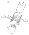
- In Fig. 4 sind der dritte Stempel 4 und der vierte Stempel 5 im Drosselklappenstutzen 2 in fast eingefahrenem Zustand dreidimensional dargestellt. Der Drosselklappenstutzen 2 weist zwei Durchbrüche B, 9 auf, durch welche eine erste Zufuhr 19 und eine zweite Zufuhr 20 für den ersten Kunststoff eingefahren sind. Sie dienen gleichzeitig zur Entlüftung des zylindrischen Hohlraums 6 (nicht dargestellt) beim ersten Spritzvorgang. Nachdem der dritte Stempel 4 und der vierte Stempel 5 in den Drosselklappenstutzen 2 eingefahren wurden, wird der erste Kunststoff über die erste Zufuhr 19 oder über die zweite Zufuhr 20 zur Bildung des Kunststoffeinsatzes 10 eingebracht. Nach Aushärtung des Kunststoffeinsatzes 10 werden der dritte Stempel 4 und der vierte Stempel 5 wieder aus dem Drosselklappenstutzen entfernt.
- In Fig. 5 ist eine Explosionsdarstellung gemäß Fig. 4 dargestellt. Dabei ist lediglich der umlaufende Vorsprung 13 des Kunststoffeinsatzes 10 durchgehend verlaufend dargestellt worden.
- In Fig. 6 ist der Drosselklappenstutzen 2 zusammen mit dem ersten Stempel 11 und dem zweiten Stempel 12 im eingefahrenen Zustand dreidimensional dargestellt. Die erste Zufuhr und die zweite Zufuhr für den ersten Kunststoff (nicht dargestellt) sind inzwischen aus der Vorrichtung herausgefahren worden und wurden durch einen ersten Stopfen 21 und einen zweiten Stopfen 22 ersetzt, die die Durchbrüche 8, 9 des Drosselklappenstutzens 2 komplementär zum Kunststoffeinsatz 10 verschließen. Zwischen dem ersten Stempel 11 und dem zweiten Stempel 12 und dem gebildeten, zur Mitte des Drosselklappenstutzens 2 verlaufenden, umlaufenden Vorsprung (nicht dargestellt) des Kunststoffeinsatzes 10 wird ein drosselklappenförmiger Hohlraum 14 (nicht dargestellt) gebildet. Anschließend wird ein aufgeschmolzener zweiter Kunststoff durch den ersten Stempel 11 in den drosselklappenförmigen Hohlraum 14 eingegeben und dort zur Aushärtung und Bildung der Drosselklappe 1 gebracht. Die Eingabe des zweiten Kunststoffs in das Innere des Drosselklappenstutzens 2 erfolgt dabei durch eine mittig im ersten Stempel 11 angeordnete Bohrung 11', Nach Aushärtung der Drosselklappe (nicht dargestellt) werden der erste Stempel 11 und der zweite Stempel 12 aus dem Drosselklappenstutzen wieder herausgefahren.
- In Fig. 7 ist eine Explosionszeichnung gemäß Fig. 6 mit einem Verbindungselement 23 dargestellt. Eine zweiteilige Drosselklappenwelle 15, 16 wird senkrecht zur Längsachse des Drosselklappenstutzens 2 durch den Drosselklappenstutzen 2 und den den Kunststoffeinsatz 10 eingebracht und die Drosselklappe 1 an der zweiteiligen Drosselklappenwelle 15, 16 befestigt. Die zweiteilige Drosselklappenwelle 15, 16 wird dabei über das verbindungselement 23 fixiert. Die eigentliche Verbindung erfolgt in besonders vorteilhafter Weise durch Lasern.
- In Fig. 8a), b) ist de Draufsicht des Kunststoffeinsatzes 10 mit der Drosselklappe 1 sowie der Querschnitt gemäß Schnitt A - A schematisch und vereinfacht dargestellt. Der umlaufende Vorsprung 13 des Kunststoffeinsatzes 10 weist dabei nicht durchgehend den gleichen Abstand zu den Kanten des Kunststoffeinsatzes 10 auf. Der maximale Winkel α zwischen der Senkrechten zur Längsachse des Drosselklappenstutzens 2 (nicht dargestellt) und der direkten Verbindung zweier direkt gegenüberliegender Bereiche 17, 18 des umlaufenden Vorsprungs 13 liegt zwischen 7° und 8°. Dies entspricht in der Regel der gewünschten Neigung der Drosselklappe 1 im Drosselklappenstutzen.
Claims (6)
- Verfahren zur Herstellung einer Drosselklappe (1) in einem durchgehenden, wenigstens teilweise aus einem ersten Kunststoff gefertigten Drosselklappenstutzen (2) mit einem zur Mitte des Drosselklappenstutzens (2) verlaufenden, umlaufenden Vorsprung (13) und mindestens einem Durchbruch (8, 9), wobei in den Drosselklappenstutzen (2) von beiden Seiten ein erster Stempel (11) und ein zweiter Stempel (12) eingefahren werden, so dass zwischen beiden Stempeln (11, 12) und dem Vorsprung (13) ein drosselklappenförmiger Hohlraum (14) gebildet wird, ein aufgeschmolzener zweiter Kunststoff durch den ersten Stempel (11) in den drosselklappenförmigen Hohlraum (14) eingegeben und dort zur Aushärtung und Bildung der Drosselklappen (1) gebracht wird sowie anschließend der erste Stempel (11) und der zweite Stempel (12) aus dem Drosselklappenstutzen (2) entfernt werden,
dadurch gekennzeichnet, dass
der mindestens eine Durchbruch (8, 9) vor dem Eingeben des zweiten Kunststoffes komplementär zum Drosselklappenstutzen (2) verschlossen wird, wobei der an der Stelle des mindestens einen Durchbruchs (8, 9) nicht vorhandene umlaufende Vorsprung (13) ergänzt wird, nach dem Entfernen des ersten Stempels (11) und des zweiten Stempels (12) aus dem Drosselklappenstutzen (2) mindestens eine Drosselklappenwelle (15, 16) senkrecht zur Längsachse des Drosselklappenstutzens (2) durch den Durchbruch (8, 9) eingebracht und die Drosselklappe (1) an der mindestens einen Drosselklappenwelle (15, 16) befestigt wird. - Verfahren nach Anspruch 1, bei dem in einem vorangehenden Verfahrensschritt in einem durchgehenden Drosselklappenstutzen (2), der bereits mit dem mindestens einen Durchbruch (8, 9) versehen ist, eine umlaufende, ringförmige Nut (3) eingearbeitet wird, anschließend von beiden Seiten ein dritter Stempel (4) und ein vierter Stempel (5) in diesen Drosselklappenstutzen (2) eingefahren werden, die zueinander komplementär gestaltet sind und im eingefahrenen Zustand im Bereich der ringförmigen Nut (3) einen zylindrischen Hohlraum (6) bilden, der zur Mitte des Drosselklappestutzens (2) einen umlaufenden Vorsprung (7) aufweist, anschließend seitlich durch den Durchbruch (8, 9) der erste Kunststoff in aufgeschmolzener Form in den zylindrischen Hohlraum (6) eingegeben und dort zur Aushärtung und Bildung eines Kunststoffeinsatzes (10) mit dem zur Mitte des Drosselklappenstutzens (2) verlaufenden, umlaufenden Vorsprung (13) gebracht wird.
- Verfahren nach Anspruch 1 oder 2, bei dem der umlaufende vorsprung (13) des Drosselklappenstutzens (2) nicht durchgehend im gleichen Abstand zu den Kanten des Drosselklappenstutzens (2) gebildet wird und der maximale Winkel α zwischen der Senkrechten zur Längsachse des Drosselklappenstutzens (2) und der direkten Verbindung zweier direkt einander gegenüberliegender Bereiche (17, 18) des umlaufenden vorsprungs (13) dabei zwischen 7° und 8° liegt.
- Verfahren nach einem der vorhergehenden Ansprüche, bei dem als erster Kunststoff und als zweiter Kunststoff Polyphenylensulfide (PPS) mit unterschiedlichen linearen Ausdehnungskoeffizienten eingesetzt werden.
- Verfahren nach Anspruch 4, bei dem als erster Kunststoff ein Polyphenylensulfid (PPS) mit einem linearen Ausdehnungskoeffizienten zwischen 90 und 200 °C von 36 · 10-6 und als zweiter Kunststoff ein Polyphenylensulfid (PES) mit einem linearen Ausdehnungskoeffizienten zwischen 90 und 250 °c von 46 · 10-6 eingesetzt wird.
- Verfahren nach einem der vorhergehenden Ansprüche, bei dem die Drosselklappe (1) an der mindestens einen Drosselklappenwelle (15, 16) durch Lasern befestigt wird.
Applications Claiming Priority (3)
| Application Number | Priority Date | Filing Date | Title |
|---|---|---|---|
| DE10229641 | 2002-07-02 | ||
| DE2002129641 DE10229641A1 (de) | 2002-07-02 | 2002-07-02 | Verfahren zur Herstellung einer Drosselklappe in einem durchgehenden Drosselklappenstutzen |
| PCT/DE2003/002018 WO2004005000A1 (de) | 2002-07-02 | 2003-06-16 | Verfahren zur herstellung einer drosselklappe in einem durchgehenden drosselklappenstutzen durch spritzgiessen von kunststoff |
Publications (2)
| Publication Number | Publication Date |
|---|---|
| EP1517776A1 EP1517776A1 (de) | 2005-03-30 |
| EP1517776B1 true EP1517776B1 (de) | 2006-04-19 |
Family
ID=29796089
Family Applications (1)
| Application Number | Title | Priority Date | Filing Date |
|---|---|---|---|
| EP03740094A Expired - Lifetime EP1517776B1 (de) | 2002-07-02 | 2003-06-16 | Verfahren zur herstellung einer drosselklappe in einem durchgehenden drosselklappenstutzen durch spritzgiessen von kunststoff |
Country Status (3)
| Country | Link |
|---|---|
| EP (1) | EP1517776B1 (de) |
| DE (2) | DE10229641A1 (de) |
| WO (1) | WO2004005000A1 (de) |
Families Citing this family (3)
| Publication number | Priority date | Publication date | Assignee | Title |
|---|---|---|---|---|
| DE102005041874A1 (de) * | 2005-09-02 | 2007-03-08 | Siemens Ag | Verfahren zur Herstellung einer Drosselklappeneinheit aus mehreren Kunststoffkomponenten |
| DE102011107608B3 (de) * | 2011-06-30 | 2012-11-15 | Pierburg Gmbh | Verfahren zum spaltlosen Montagespritzen zweier Komponenten sowie Klappenvorrichtung für eine Verbrennungskraftmaschine |
| DE102018125093B4 (de) * | 2018-10-10 | 2021-05-06 | smk systeme metall kunststoff gmbh & co. kg | Verfahren zum Herstellen eines Klappenventils für die Abgasanlage eines Verbrennungsmotors |
Family Cites Families (16)
| Publication number | Priority date | Publication date | Assignee | Title |
|---|---|---|---|---|
| DE3123146A1 (de) * | 1981-06-11 | 1982-12-30 | Klaus Ing. Regitz (grad.), 6654 Limbach | Verfahren zum herstellen des sitzes fuer ventilverschlussstuecke und ventilausbildung mit gehaeuse, verchlussstueck und ventilsitz |
| JPS59120433A (ja) * | 1982-12-27 | 1984-07-12 | Du Pont Mitsui Fluorochem Co Ltd | ライニング方法 |
| DE69020567C5 (de) * | 1990-10-24 | 2007-08-16 | Volvo Car Corp. | Ventilanordnung. |
| FR2687601A1 (fr) * | 1992-02-26 | 1993-08-27 | Plastic Omnium Cie | Procede de fabrication d'une vanne papillon, dispositif pour le mettre en óoeuvre et vanne papillon obtenue par ce procede. |
| FR2692622B1 (fr) * | 1992-06-17 | 1994-09-16 | Solex | Organe d'étranglement rotatif pour installation d'alimentation de moteur à combustion interne et corps de papillon en comportant application. |
| DE4323078A1 (de) * | 1993-07-10 | 1995-01-12 | Pierburg Gmbh | Drosselklappenstutzen für Brennkraftmaschinen |
| ES2119415T5 (es) * | 1994-03-31 | 2005-03-16 | Marquardt Gmbh | Pieza de plastico y procedimiento de fabricacion para una pieza de esta clase. |
| SE9402882D0 (sv) * | 1994-08-31 | 1994-08-31 | Volvo Ab | Butterfly valve assembly |
| DE19615438A1 (de) * | 1995-07-17 | 1997-01-23 | Mann & Hummel Filter | Ventil |
| US5715782A (en) * | 1996-08-29 | 1998-02-10 | Genral Motors Corporation | Composite molded butterfly valve for an internal combustion engine |
| JPH11229909A (ja) * | 1998-02-09 | 1999-08-24 | Nissan Motor Co Ltd | 樹脂製空気量制御装置 |
| JPH11294201A (ja) * | 1998-04-06 | 1999-10-26 | Mitsubishi Eng Plast Corp | 内燃機関の吸入空気制御装置 |
| US6451238B1 (en) * | 1998-04-07 | 2002-09-17 | Honda Giken Kogyo Kabushiki Kaisha | Process for producing intake member of resin, and intake member of resin |
| DE19841181B4 (de) * | 1998-09-09 | 2009-10-15 | Robert Bosch Gmbh | Drosselklappenstutzen zum Steuern der Leistung einer Brennkraftmaschine und Verfahren zum Anbauen einer Drosselklappe |
| DE10018627C1 (de) * | 2000-04-14 | 2002-06-13 | Saxonia Umformtechnik Gmbh | Drosselklappe |
| US6589380B2 (en) * | 2001-02-07 | 2003-07-08 | Delphi Technologies, Inc. | Laser welded air control valve and method |
-
2002
- 2002-07-02 DE DE2002129641 patent/DE10229641A1/de not_active Withdrawn
-
2003
- 2003-06-16 EP EP03740094A patent/EP1517776B1/de not_active Expired - Lifetime
- 2003-06-16 DE DE50303043T patent/DE50303043D1/de not_active Expired - Lifetime
- 2003-06-16 WO PCT/DE2003/002018 patent/WO2004005000A1/de not_active Ceased
Also Published As
| Publication number | Publication date |
|---|---|
| EP1517776A1 (de) | 2005-03-30 |
| DE10229641A1 (de) | 2004-01-29 |
| DE50303043D1 (de) | 2006-05-24 |
| WO2004005000A1 (de) | 2004-01-15 |
Similar Documents
| Publication | Publication Date | Title |
|---|---|---|
| EP2598267B1 (de) | Gesenk und verfahren zum schmieden | |
| DE102016203627B3 (de) | Verfahren zur Herstellung einer längenveränderbaren Lenkwelle und Spritzgießvorrichtung zur Durchführung des Verfahrens | |
| CH712554A1 (de) | Spritzgusswerkzeug mit justierbarer Kernzentrierungseinrichtung. | |
| EP1554099B1 (de) | Verfahren zur herstellung einer drosselklappe in einem durchgehenden drosselklappenstutzen | |
| DE19631963C2 (de) | Spritzgießform | |
| DE4329526A1 (de) | Drosseleinrichtung | |
| EP1517776B1 (de) | Verfahren zur herstellung einer drosselklappe in einem durchgehenden drosselklappenstutzen durch spritzgiessen von kunststoff | |
| EP3482905B1 (de) | Formwerkzeug sowie verfahren zum formen eines bauteils | |
| DE4137805A1 (de) | Verfahren zur herstellung eines kolbenschiebers sowie vorrichtung zur durchfuehrung des verfahrens | |
| DE1911600C3 (de) | Mehrteilige Form zum Pressen oder Blasen von thermoplastischen Materialien | |
| DE102004016832B4 (de) | Vorrichtung zum teilweisen Umspritzen metallischer Einleger mit einem Spritzgießwerkzeug | |
| EP1534491B1 (de) | Verfahren zum abschliessen eines drosselklappenstutzens | |
| DE102009014567B4 (de) | Werkzeug zur Herstellung von Sandkernen oder Gusswerkzeug zur Herstellung von Gussprodukten | |
| DE69722679T2 (de) | Formwerkzeug zur Herstellung eines Zahnrades in Verbundbauweise und Verfahren zur Herstellung eines solchen Werkzeuges | |
| DE19757387A1 (de) | Spritzgießvorrichtung | |
| DE102008024200B4 (de) | Schaltwelle | |
| DE19918776A1 (de) | Formwerkzeug zur Herstellung von mehreren montagegespritzten Bauteilen | |
| DE3734118C2 (de) | ||
| DE3508225C2 (de) | ||
| EP4061603B1 (de) | Einteiliges gussbauteil mit wenigstens einem integrierten anbauteil und verfahren zum herstellen eines gussbauteils | |
| DE102009014566A1 (de) | Gusswerkzeug | |
| DE102017121136A1 (de) | Steuerkolben aus Kunststoff, Werkzeug und Verfahren zur Herstellung eines Steuerkolbens | |
| DE102018211566A1 (de) | Werkzeug und Verfahren zum Verpressen eines Hilfsfügeelements mit einem separat von dem Hilfsfügeelement ausgebildeten Werkstück, insbesondere zum Herstellen eines Kraftfahrzeugs | |
| DE102007015216A1 (de) | Vorrichtung und Verfahren zur Herstellung eines Hohlkörpers aus mindestens zwei Schichten Kunststoff | |
| DE102012101959A1 (de) | Werkzeugvorrichtung |
Legal Events
| Date | Code | Title | Description |
|---|---|---|---|
| PUAI | Public reference made under article 153(3) epc to a published international application that has entered the european phase |
Free format text: ORIGINAL CODE: 0009012 |
|
| 17P | Request for examination filed |
Effective date: 20041201 |
|
| AK | Designated contracting states |
Kind code of ref document: A1 Designated state(s): AT BE BG CH CY CZ DE DK EE ES FI FR GB GR HU IE IT LI LU MC NL PT RO SE SI SK TR |
|
| 17Q | First examination report despatched |
Effective date: 20050408 |
|
| GRAP | Despatch of communication of intention to grant a patent |
Free format text: ORIGINAL CODE: EPIDOSNIGR1 |
|
| RBV | Designated contracting states (corrected) |
Designated state(s): DE FR IT |
|
| GRAS | Grant fee paid |
Free format text: ORIGINAL CODE: EPIDOSNIGR3 |
|
| GRAA | (expected) grant |
Free format text: ORIGINAL CODE: 0009210 |
|
| AK | Designated contracting states |
Kind code of ref document: B1 Designated state(s): DE FR IT |
|
| PG25 | Lapsed in a contracting state [announced via postgrant information from national office to epo] |
Ref country code: IT Free format text: LAPSE BECAUSE OF FAILURE TO SUBMIT A TRANSLATION OF THE DESCRIPTION OR TO PAY THE FEE WITHIN THE PRESCRIBED TIME-LIMIT;WARNING: LAPSES OF ITALIAN PATENTS WITH EFFECTIVE DATE BEFORE 2007 MAY HAVE OCCURRED AT ANY TIME BEFORE 2007. THE CORRECT EFFECTIVE DATE MAY BE DIFFERENT FROM THE ONE RECORDED. Effective date: 20060419 |
|
| REF | Corresponds to: |
Ref document number: 50303043 Country of ref document: DE Date of ref document: 20060524 Kind code of ref document: P |
|
| PLBE | No opposition filed within time limit |
Free format text: ORIGINAL CODE: 0009261 |
|
| STAA | Information on the status of an ep patent application or granted ep patent |
Free format text: STATUS: NO OPPOSITION FILED WITHIN TIME LIMIT |
|
| 26N | No opposition filed |
Effective date: 20070122 |
|
| EN | Fr: translation not filed | ||
| PG25 | Lapsed in a contracting state [announced via postgrant information from national office to epo] |
Ref country code: FR Free format text: LAPSE BECAUSE OF FAILURE TO SUBMIT A TRANSLATION OF THE DESCRIPTION OR TO PAY THE FEE WITHIN THE PRESCRIBED TIME-LIMIT Effective date: 20070309 |
|
| PG25 | Lapsed in a contracting state [announced via postgrant information from national office to epo] |
Ref country code: FR Free format text: LAPSE BECAUSE OF FAILURE TO SUBMIT A TRANSLATION OF THE DESCRIPTION OR TO PAY THE FEE WITHIN THE PRESCRIBED TIME-LIMIT Effective date: 20060419 |
|
| PGFP | Annual fee paid to national office [announced via postgrant information from national office to epo] |
Ref country code: DE Payment date: 20120630 Year of fee payment: 10 |
|
| REG | Reference to a national code |
Ref country code: DE Ref legal event code: R119 Ref document number: 50303043 Country of ref document: DE Effective date: 20140101 |
|
| PG25 | Lapsed in a contracting state [announced via postgrant information from national office to epo] |
Ref country code: DE Free format text: LAPSE BECAUSE OF NON-PAYMENT OF DUE FEES Effective date: 20140101 |