EP1270833B1 - Elément de construction pour l'isolation thermique - Google Patents
Elément de construction pour l'isolation thermique Download PDFInfo
- Publication number
- EP1270833B1 EP1270833B1 EP02008611A EP02008611A EP1270833B1 EP 1270833 B1 EP1270833 B1 EP 1270833B1 EP 02008611 A EP02008611 A EP 02008611A EP 02008611 A EP02008611 A EP 02008611A EP 1270833 B1 EP1270833 B1 EP 1270833B1
- Authority
- EP
- European Patent Office
- Prior art keywords
- construction element
- fastening devices
- plate
- insulating body
- lower portion
- Prior art date
- Legal status (The legal status is an assumption and is not a legal conclusion. Google has not performed a legal analysis and makes no representation as to the accuracy of the status listed.)
- Expired - Lifetime
Links
Images


Classifications
-
- E—FIXED CONSTRUCTIONS
- E04—BUILDING
- E04B—GENERAL BUILDING CONSTRUCTIONS; WALLS, e.g. PARTITIONS; ROOFS; FLOORS; CEILINGS; INSULATION OR OTHER PROTECTION OF BUILDINGS
- E04B1/00—Constructions in general; Structures which are not restricted either to walls, e.g. partitions, or floors or ceilings or roofs
- E04B1/003—Balconies; Decks
- E04B1/0038—Anchoring devices specially adapted therefor with means for preventing cold bridging
-
- E—FIXED CONSTRUCTIONS
- E04—BUILDING
- E04B—GENERAL BUILDING CONSTRUCTIONS; WALLS, e.g. PARTITIONS; ROOFS; FLOORS; CEILINGS; INSULATION OR OTHER PROTECTION OF BUILDINGS
- E04B1/00—Constructions in general; Structures which are not restricted either to walls, e.g. partitions, or floors or ceilings or roofs
- E04B1/18—Structures comprising elongated load-supporting parts, e.g. columns, girders, skeletons
- E04B1/24—Structures comprising elongated load-supporting parts, e.g. columns, girders, skeletons the supporting parts consisting of metal
- E04B1/2403—Connection details of the elongated load-supporting parts
- E04B2001/2448—Connections between open section profiles
Definitions
- the invention relates to a device for thermal insulation between a building and a projecting outer part, in particular in steel construction, consisting from an insulating body to be laid therebetween with integrated tension, pressure and optionally also transverse force elements, wherein at least some of these elements on the side facing away from the building of the insulating body and on the Building facing side of the insulating plate-like fastening devices to connect the outdoor unit with the building.
- a device for thermal insulation between a building and a projecting outer part, in particular in steel construction consisting from an insulating body to be laid therebetween with integrated tension, pressure and optionally also transverse force elements, wherein at least some of these elements on the side facing away from the building of the insulating body and on the Building facing side of the insulating plate-like fastening devices to connect the outdoor unit with the building.
- a device is known from DE-A-34 03537.
- the plate-like fastening devices arranged in the form of plates, extending throughout the whole height extend the insulating body.
- the plate-like design of the fastening device There are several advantages: First, a large area Connection base created at the connection parts particularly safe and good can be anchored. Second, the insulator is in the area between the Panels protected against damage. Third, the plates provide defined connection points, where the steel profiles with their precisely worked and easily attach inflexible connection flanges. The plates are through intersecting, transverse in a vertical plane transverse force rods with each other connected, so that a unit of insulating body and fasteners arises. In the upper area, this unit has one or more through holes for tension rods, in the lower area corresponding holes for pressure rods.
- the invention is based on the realization that in steel - unlike in Concrete construction - connecting parts with very different geometrical dimensions must be connected to the heat-insulating component. Therefore the components of the invention in a large variety of types for Available, according to the different standard dimensions of the to be connected Components that are usually 1-carrier.
- the insulator are in the range between two equal fixing devices designed in several parts, so that they the integrated reinforcing elements as possible enclose without gap.
- the separation of the insulating body is preferably carried out in a horizontal plane.
- transverse force bars form a stiffening in the vertical direction. It is in contrast to the tension and compression bars not necessary that the transverse force bars after passing through the insulating body on the other Side of the plate-shaped fastening devices emerge again. expedient this stiffening takes place in the vertical direction by two inclined, intersecting, mirror-image arranged rods or by a between the plate-shaped fastening devices inserted one-piece sheet metal.
- a stiffener is installed in the horizontal direction.
- This stiffening in the horizontal direction for example, also by two obliquely intersecting, mirror-image arranged rods done. It is, however conceivable that they are formed by two parallel bars or a plate becomes.
- the horizontal bracing is preferably in the upper region of the lower part arranged.
- stiffener between facing fasteners both in the horizontal direction as well as in the vertical direction it is recommended itself to use a one-piece profiled intermediate element, such as a T-profile or a U-profile. As a result, with one element both stiffening directions be covered.
- the plate-like fasteners in side by side and / or superimposed elements too divide.
- the fastening device of the upper part consist of two adjacent elements, so that, for example, each tie rod each associated with a plate-like fastening device at its end can be, which then reduces to the size of a screw washer can be.
- the upper part of the fastening device is normally used to hold Tensile forces, the lower part for absorbing compressive forces.
- the upper part optionally also for the transmission of compressive forces
- the lower part optionally also be used for the transmission of tensile forces.
- the vertical and / or horizontal stiffeners are depending on the load case arranged in the lower part and / or upper part of the component.
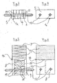
- Figure 1 can be seen a component 1 for thermal insulation between a building-side vertical steel girder 2 and a horizontally projecting outer part 3 in the form of an I-profile beam.
- the device can also be two horizontal or vertical Connecting beams together.
- the component 1 consists of an upper part 1a (see also FIGS. 3 and 4) and a lower part 1b (see also FIGS. 5 and 6).
- the upper part 1a consists of an insulating body 4, which at its the building side facing a plate-like fastening device 5 and at its the Building facing away from a similar plate-like fastening device 6 carries.
- These fastening devices consist in the present case rectangular steel plates that cover the insulating body 4 over the entire surface and flush.
- the lower part 1b consists of an insulating body 4 aligned insulating 7, which on its side facing the building one with the plate 5 in alignment Steel plate 8 and on its side facing away from the building one with the plate. 6 aligned steel plate 9 carries.
- the plates 8 and 9 are in height shorter than the insulating body, so that it protrudes upward and on Insulating body 4 abuts, while the plates 5 and 8 on the one hand and 6 and 9 on the other vertically distanced from each other.
- the upper part 1a is traversed by tension rods 10 in the horizontal direction.
- the Tension rods 10 are fixed with welds 11 to the plates 5 and 6. Instead of the welds could also be done through lock nuts or one waives an attachment and the plates 5 and 6 have only Through holes for subsequent insertion of the tension rods 10 in the Assembly of the outer part 3.
- the lower part 1 b is crossed horizontally by pressure bars 12.
- the printing bars 12 are connected by welded joints 11 with the plates 8 and 9. additionally to the pressure bars 12 are in the lower part 1b stiffeners 13 in the vertical direction and stiffeners 14 integrated in the horizontal direction. Both stiffeners are formed by two intersecting, mirror-image arranged rods. They serve to absorb shear forces.
- one of the insulating body in the embodiment the insulating body 7 of the lower part, in its the plates 8 and 9 projecting area several horizontal parting lines or predetermined separation points (see also Figures 5 and 6).
- the insulating body 7 in its height be trimmed so that upper part 1a and lower part 1b to be connected to the one Components 2 and 3 obtained appropriate height.
- Figure 2 can be seen the two adjacent tension rods 10; Furthermore the horizontal brace 14 in the lower fastening device in Form of two oblique, intersecting, mirror images in a horizontal plane arranged bars.
- the horizontal stiffener to accommodate horizontal Transverse forces can also be caused by two parallel bars or one Plate are formed.
- the upper part 1a and the lower part 1b each have horizontal through holes for the tension rods 10 and the pressure rods 12. These rods show after Traversing the plates a supernatant for attachment of the invention Component on the one hand on the building, ie on the vertical steel beam 2, on the other for mounting the projecting outer part, so the profile carrier 3.
- This Overhang preferably has a thread, so that the individual parts releasably fastened over nuts.
- FIGS. 3 and 4 only the upper part 1a of the component is shown, while FIG Figures 5 and 6 show the lower part 1b of the device.
- FIGS. 5 and 6 again recognizes the predetermined horizontal separation areas 15 in Area between the upper and lower attachment devices. Of course These separation areas could also be added to the upper insulating body 4 be.
- FIG. 8 shows a component in which a plurality of upper parts 1a and a plurality of lower parts 1b are combined. Depending on the static load can be through this modular Construction matching connections also made for special applications become.
- the Isolier Economicsmaschine can with each other and with their both sides plate-like fasteners to be firmly connected, such as by gluing. Usually, however, it is sufficient if they simply between the fastening devices are stuck. Also a subsequent foaming of the gap between the fastening devices may be appropriate, if necessary only after installation on site.
- the device according to the invention for thermal insulation in steel construction characterized by steel beams of different heights and Width can be connected to one and the same standardized component.
Landscapes
- Engineering & Computer Science (AREA)
- Architecture (AREA)
- Physics & Mathematics (AREA)
- Electromagnetism (AREA)
- Civil Engineering (AREA)
- Structural Engineering (AREA)
- Building Environments (AREA)
- Removal Of Water From Condensation And Defrosting (AREA)
- Connector Housings Or Holding Contact Members (AREA)
- Cooling Or The Like Of Electrical Apparatus (AREA)
- Joining Of Building Structures In Genera (AREA)
- Insulated Conductors (AREA)
- Macromolecular Compounds Obtained By Forming Nitrogen-Containing Linkages In General (AREA)
Claims (14)
- Élément de construction (1) pour l'isolation thermique entre un bâtiment (2) et une partie extérieure (3) en saillie, notamment dans le domaine de la construction métallique, constitué d'un corps isolant à poser entre ceux-ci et dans lequel sont guidés des éléments de traction, de pression et éventuellement de force transversale, sachant qu'au moins quelques-uns de ces éléments portent, sur le côté du corps isolant qui est opposé au bâtiment et sur le côté du corps isolant qui est tourné vers le bâtiment, des dispositifs de fixation du genre plaques pour l'assemblage de la partie extérieure au bâtiment,
caractérisé en ce que le corps isolant conjointement avec ses dispositifs de fixation du genre plaques est divisé en au moins une partie supérieure (1a) et une partie inférieure (1b), en ce que les dispositifs de fixation du genre plaques (5, 6) de la partie supérieure (1a) sont associés aux éléments de traction (10) et les dispositifs de fixation (8, 9) de la partie inférieure (1b) sont reliés aux éléments de pression (12), et en ce que les dispositifs de fixation du genre plaques (5, 6 ; 8, 9) de la partie supérieure et de la partie inférieure sont verticalement distants les uns des autres, tandis que les parties de corps isolant (4, 7) se suivent sans un tel espacement. - Élément de construction selon la revendication 1, caractérisé en ce que les parties de corps isolant (4, 7) sont réalisées en plusieurs parties dans la région située entre deux dispositifs de fixation (5, 6 ; 8, 9) situés à la même hauteur.
- Élément de construction selon la revendication 1, caractérisé en ce que la partie de corps isolant (7) présente, dans la région située entre les dispositifs de fixation supérieurs et inférieurs, plusieurs zones de séparation horizontales prédéfinies (15) de hauteurs échelonnées.
- Élément de construction selon la revendication 1, caractérisé en ce que la partie de corps isolant (7) fait saillie en direction horizontale dans l'espace intermédiaire entre les dispositifs de fixation du genre plaques supérieurs et inférieurs et éventuellement sur le côté des dispositifs de fixation, et se termine à fleur des côtés extérieurs des dispositifs de fixation.
- Élément de construction selon la revendication 1, caractérisé en ce qu'un renforcement en direction verticale (13) est incorporé entre les dispositifs (5, 6) de fixation de la partie supérieure et/ou les dispositifs de fixation (8, 9) de la partie inférieure.
- Élément de construction selon la revendication 5, caractérisé en ce que le renforcement en direction verticale (13) s'effectue par deux barres s'étendant en oblique, qui se croisent et sont disposées symétriquement, ou par une plaque.
- Élément de construction selon la revendication 1, caractérisé en ce qu'un renforcement en direction horizontale (14) est incorporé entre les dispositifs de fixation de la partie supérieure (1a) et/ou de la partie inférieure (1b).
- Élément de construction au moins selon la revendication 7, caractérisé en ce que le renforcement en direction horizontale (14) s'effectue par deux barres s'étendant en oblique, qui se croisent et sont disposées symétriquement, ou par au moins deux barres s'étendant parallèlement, ou par une plaque.
- Élément de construction au moins selon les revendications 5 et 7, caractérisé en ce que le renforcement vertical et/ou le renforcement horizontal sont disposés dans la partie inférieure (1b) de l'élément de construction.
- Élément de construction au moins selon la revendication 9, caractérisé en ce que le renforcement horizontal (14) est disposé dans la région supérieure de la partie inférieure (1b).
- Élément de construction selon les revendications 5 et 7, caractérisé en ce que le renforcement vertical et le renforcement horizontal sont formés par un profilé d'un seul tenant, notamment un profilé en T.
- Élément de construction selon la revendication 1, caractérisé en ce que les dispositifs de fixation du genre plaques (5, 6, 8, 9) de la partie supérieure et de la partie inférieure sont de dimensions différentes.
- Élément de construction selon la revendication 1, caractérisé en ce que les dispositifs de fixation du genre plaques sont subdivisés en éléments disposés en juxtaposition et/ou en superposition.
- Élément de construction selon au moins une des revendications précédentes, caractérisé en ce que la partie supérieure (1a) peut être sélectivement utilisée également pour la transmission de forces de pression, et la partie inférieure (1b) peut être sélectivement utilisée également pour la transmission de forces de traction.
Applications Claiming Priority (2)
| Application Number | Priority Date | Filing Date | Title |
|---|---|---|---|
| DE10130866A DE10130866A1 (de) | 2001-06-22 | 2001-06-22 | Bauelement zur Wärmedämmung |
| DE10130866 | 2001-06-22 |
Publications (3)
| Publication Number | Publication Date |
|---|---|
| EP1270833A2 EP1270833A2 (fr) | 2003-01-02 |
| EP1270833A3 EP1270833A3 (fr) | 2003-12-03 |
| EP1270833B1 true EP1270833B1 (fr) | 2005-12-28 |
Family
ID=7689554
Family Applications (1)
| Application Number | Title | Priority Date | Filing Date |
|---|---|---|---|
| EP02008611A Expired - Lifetime EP1270833B1 (fr) | 2001-06-22 | 2002-04-17 | Elément de construction pour l'isolation thermique |
Country Status (4)
| Country | Link |
|---|---|
| EP (1) | EP1270833B1 (fr) |
| AT (1) | ATE314535T1 (fr) |
| DE (2) | DE10130866A1 (fr) |
| PL (1) | PL206390B1 (fr) |
Families Citing this family (8)
| Publication number | Priority date | Publication date | Assignee | Title |
|---|---|---|---|---|
| DE102006011335A1 (de) * | 2006-03-09 | 2007-09-13 | Schöck Bauteile GmbH | Bauelement zur Wärmedämmung |
| DE102007061000A1 (de) * | 2007-12-18 | 2009-06-25 | Fischerwerke Gmbh & Co. Kg | Befestigungselement |
| DE102011056967A1 (de) * | 2011-12-23 | 2013-06-27 | Max Frank Gmbh & Co. Kg | Plattenanschlusselement |
| AT513322B1 (de) * | 2012-09-06 | 2014-10-15 | Hans Höllwart Forschungszentrum Für Integrales Bauwesen Ag | Thermisch isolierendes Tragelement |
| DE102014113662A1 (de) | 2014-09-22 | 2016-03-24 | Max Frank Gmbh & Co. Kg | Anschlusselement |
| DE102019118363B4 (de) | 2019-07-08 | 2021-07-15 | Max Frank Gmbh & Co. Kg | Anordnung zum Verbinden eines Bauwerkteils mit einem dem Bauwerkteil vorgelagerten Stahl-Außenteil |
| DE102019133997A1 (de) | 2019-12-11 | 2021-06-17 | Max Frank Gmbh & Co. Kg | Anordnung zum Verbinden eines Bauwerkteils mit einem dem Bauwerkteil vorgelagerten Außenteil |
| GB2583314B (en) * | 2020-07-23 | 2022-11-02 | Laing Orourke Plc | Façade construction using through wall thermal stud |
Family Cites Families (3)
| Publication number | Priority date | Publication date | Assignee | Title |
|---|---|---|---|---|
| DE3403537A1 (de) * | 1984-02-02 | 1985-08-08 | Veit Dennert KG Baustoffbetriebe, 8602 Schlüsselfeld | Balkonfertig-bauelement fuer gebaeude |
| CH690966A5 (de) * | 1996-03-12 | 2001-03-15 | Clement Gutzwiller | Isolierendes Anschlusselement für Kragplatten. |
| DE19908388B4 (de) | 1999-02-26 | 2008-10-30 | Schöck Bauteile GmbH | Bauelement zur Wärmedämmung |
-
2001
- 2001-06-22 DE DE10130866A patent/DE10130866A1/de not_active Withdrawn
-
2002
- 2002-04-17 EP EP02008611A patent/EP1270833B1/fr not_active Expired - Lifetime
- 2002-04-17 DE DE50205404T patent/DE50205404D1/de not_active Expired - Lifetime
- 2002-04-17 AT AT02008611T patent/ATE314535T1/de active
- 2002-06-11 PL PL354429A patent/PL206390B1/pl unknown
Also Published As
| Publication number | Publication date |
|---|---|
| PL206390B1 (pl) | 2010-08-31 |
| PL354429A1 (en) | 2002-12-30 |
| ATE314535T1 (de) | 2006-01-15 |
| DE50205404D1 (de) | 2006-02-02 |
| EP1270833A3 (fr) | 2003-12-03 |
| DE10130866A1 (de) | 2003-01-02 |
| EP1270833A2 (fr) | 2003-01-02 |
Similar Documents
| Publication | Publication Date | Title |
|---|---|---|
| DE69406930T2 (de) | Leichte leitschranken für brücken | |
| EP0040815B1 (fr) | Poutre composite dans la construction préfabriquée | |
| DE1903129B2 (de) | Vorrichtung zum Anschließen eines Trägers an eine Betonstütze | |
| DE1684795B2 (de) | Raumkasten mit Betonwandungen, die von Metall-Profilbalken eingefaßt sind | |
| DE3128165C2 (de) | Schalldämmendes Wandbausystem für Industriebauten, sowie Kassettenprofil hierfür | |
| DE1810434C3 (de) | Hochbauwerk | |
| EP1270833B1 (fr) | Elément de construction pour l'isolation thermique | |
| DE102018131066A1 (de) | Bewehrung, Betonelement, Modulverbindung, Modulblock sowie Gebäude | |
| EP1031668B1 (fr) | Elément de construction pour l'isolation thermique | |
| EP2281959A1 (fr) | Elément de connexion pour dalle en porte-à-faux | |
| EP0563707B1 (fr) | Panneau de coffrage | |
| DE102019133999A1 (de) | Anordnung zum Verbinden eines Bauwerkteils mit einem dem Bauwerkteil vorgelagerten Außenteil | |
| EP0133875B1 (fr) | Elément de construction isolant thermique pour bâtiments | |
| DE3318431C2 (de) | Deckenelement | |
| CH651095A5 (de) | Bewehrungselement zur uebertragung von querkraeften in plattenartigen traggliedern, z.b. flachdecken. | |
| EP1860246B1 (fr) | Elément de construction pour isolation thermique | |
| EP1387910B1 (fr) | Element de raccordement et procede de raccordement d'un composant en beton prefabrique a une partie d'un immeuble | |
| DE9409626U1 (de) | Balkonkonstruktion | |
| EP2607560B1 (fr) | Élément de raccordement de dalle | |
| DE202021101776U1 (de) | Einrichtung zur nachträglichen thermisch isolierenden, kraftübertragenden Anbindung eines zweiten lastaufnehmenden Bauwerksteils an ein erstes lastaufnehmendes Bauwerksteil und Bauwerk mit einer solchen Einrichtung | |
| EP3569783B1 (fr) | Composant destiné à l'isolation thermique | |
| DE2336482A1 (de) | Raumzelle fuer gebaeude | |
| DE69001688T2 (de) | Verfahren zur befestigung von horizontalen balken an stahlsaeulen eines gebaeudes und ein nach diesem verfahren errichtetes gebaeude. | |
| DE102008002899A1 (de) | Bauelement mit Edelstahlträger | |
| DE102016118014A1 (de) | Binder, insbesondere Dachbinder für eine Halle |
Legal Events
| Date | Code | Title | Description |
|---|---|---|---|
| PUAI | Public reference made under article 153(3) epc to a published international application that has entered the european phase |
Free format text: ORIGINAL CODE: 0009012 |
|
| AK | Designated contracting states |
Kind code of ref document: A2 Designated state(s): AT BE CH CY DE DK ES FI FR GB GR IE IT LI LU MC NL PT SE TR |
|
| AX | Request for extension of the european patent |
Free format text: AL;LT;LV;MK;RO;SI |
|
| PUAL | Search report despatched |
Free format text: ORIGINAL CODE: 0009013 |
|
| AK | Designated contracting states |
Kind code of ref document: A3 Designated state(s): AT BE CH CY DE DK ES FI FR GB GR IE IT LI LU MC NL PT SE TR |
|
| AX | Request for extension of the european patent |
Extension state: AL LT LV MK RO SI |
|
| 17P | Request for examination filed |
Effective date: 20040206 |
|
| AKX | Designation fees paid |
Designated state(s): AT BE CH CY DE DK ES FI FR GB GR IE IT LI LU MC NL PT SE TR |
|
| RAP1 | Party data changed (applicant data changed or rights of an application transferred) |
Owner name: SCHOECK BAUTEILE GMBH |
|
| GRAP | Despatch of communication of intention to grant a patent |
Free format text: ORIGINAL CODE: EPIDOSNIGR1 |
|
| GRAP | Despatch of communication of intention to grant a patent |
Free format text: ORIGINAL CODE: EPIDOSNIGR1 |
|
| GRAS | Grant fee paid |
Free format text: ORIGINAL CODE: EPIDOSNIGR3 |
|
| GRAA | (expected) grant |
Free format text: ORIGINAL CODE: 0009210 |
|
| AK | Designated contracting states |
Kind code of ref document: B1 Designated state(s): AT BE CH CY DE DK ES FI FR GB GR IE IT LI LU MC NL PT SE TR |
|
| PG25 | Lapsed in a contracting state [announced via postgrant information from national office to epo] |
Ref country code: FI Free format text: LAPSE BECAUSE OF FAILURE TO SUBMIT A TRANSLATION OF THE DESCRIPTION OR TO PAY THE FEE WITHIN THE PRESCRIBED TIME-LIMIT Effective date: 20051228 Ref country code: IT Free format text: LAPSE BECAUSE OF FAILURE TO SUBMIT A TRANSLATION OF THE DESCRIPTION OR TO PAY THE FEE WITHIN THE PRESCRIBED TIME-LIMIT;WARNING: LAPSES OF ITALIAN PATENTS WITH EFFECTIVE DATE BEFORE 2007 MAY HAVE OCCURRED AT ANY TIME BEFORE 2007. THE CORRECT EFFECTIVE DATE MAY BE DIFFERENT FROM THE ONE RECORDED. Effective date: 20051228 |
|
| REG | Reference to a national code |
Ref country code: GB Ref legal event code: FG4D Free format text: NOT ENGLISH |
|
| REG | Reference to a national code |
Ref country code: CH Ref legal event code: EP |
|
| REG | Reference to a national code |
Ref country code: IE Ref legal event code: FG4D Free format text: LANGUAGE OF EP DOCUMENT: GERMAN |
|
| REF | Corresponds to: |
Ref document number: 50205404 Country of ref document: DE Date of ref document: 20060202 Kind code of ref document: P |
|
| REG | Reference to a national code |
Ref country code: CH Ref legal event code: NV Representative=s name: R. A. EGLI & CO. PATENTANWAELTE |
|
| PG25 | Lapsed in a contracting state [announced via postgrant information from national office to epo] |
Ref country code: SE Free format text: LAPSE BECAUSE OF FAILURE TO SUBMIT A TRANSLATION OF THE DESCRIPTION OR TO PAY THE FEE WITHIN THE PRESCRIBED TIME-LIMIT Effective date: 20060328 Ref country code: GR Free format text: LAPSE BECAUSE OF FAILURE TO SUBMIT A TRANSLATION OF THE DESCRIPTION OR TO PAY THE FEE WITHIN THE PRESCRIBED TIME-LIMIT Effective date: 20060328 Ref country code: DK Free format text: LAPSE BECAUSE OF FAILURE TO SUBMIT A TRANSLATION OF THE DESCRIPTION OR TO PAY THE FEE WITHIN THE PRESCRIBED TIME-LIMIT Effective date: 20060328 |
|
| PG25 | Lapsed in a contracting state [announced via postgrant information from national office to epo] |
Ref country code: ES Free format text: LAPSE BECAUSE OF FAILURE TO SUBMIT A TRANSLATION OF THE DESCRIPTION OR TO PAY THE FEE WITHIN THE PRESCRIBED TIME-LIMIT Effective date: 20060408 |
|
| GBT | Gb: translation of ep patent filed (gb section 77(6)(a)/1977) |
Effective date: 20060329 |
|
| PG25 | Lapsed in a contracting state [announced via postgrant information from national office to epo] |
Ref country code: MC Free format text: LAPSE BECAUSE OF NON-PAYMENT OF DUE FEES Effective date: 20060430 Ref country code: BE Free format text: LAPSE BECAUSE OF NON-PAYMENT OF DUE FEES Effective date: 20060430 |
|
| PG25 | Lapsed in a contracting state [announced via postgrant information from national office to epo] |
Ref country code: PT Free format text: LAPSE BECAUSE OF FAILURE TO SUBMIT A TRANSLATION OF THE DESCRIPTION OR TO PAY THE FEE WITHIN THE PRESCRIBED TIME-LIMIT Effective date: 20060529 |
|
| ET | Fr: translation filed | ||
| PLBE | No opposition filed within time limit |
Free format text: ORIGINAL CODE: 0009261 |
|
| STAA | Information on the status of an ep patent application or granted ep patent |
Free format text: STATUS: NO OPPOSITION FILED WITHIN TIME LIMIT |
|
| 26N | No opposition filed |
Effective date: 20060929 |
|
| BERE | Be: lapsed |
Owner name: SCHOCK BAUTEILE G.M.B.H. Effective date: 20060430 |
|
| PG25 | Lapsed in a contracting state [announced via postgrant information from national office to epo] |
Ref country code: LU Free format text: LAPSE BECAUSE OF NON-PAYMENT OF DUE FEES Effective date: 20060417 Ref country code: TR Free format text: LAPSE BECAUSE OF FAILURE TO SUBMIT A TRANSLATION OF THE DESCRIPTION OR TO PAY THE FEE WITHIN THE PRESCRIBED TIME-LIMIT Effective date: 20051228 |
|
| PG25 | Lapsed in a contracting state [announced via postgrant information from national office to epo] |
Ref country code: CY Free format text: LAPSE BECAUSE OF FAILURE TO SUBMIT A TRANSLATION OF THE DESCRIPTION OR TO PAY THE FEE WITHIN THE PRESCRIBED TIME-LIMIT Effective date: 20051228 |
|
| REG | Reference to a national code |
Ref country code: FR Ref legal event code: PLFP Year of fee payment: 15 |
|
| REG | Reference to a national code |
Ref country code: FR Ref legal event code: PLFP Year of fee payment: 16 |
|
| REG | Reference to a national code |
Ref country code: FR Ref legal event code: PLFP Year of fee payment: 17 |
|
| PGFP | Annual fee paid to national office [announced via postgrant information from national office to epo] |
Ref country code: IE Payment date: 20180418 Year of fee payment: 17 |
|
| PGFP | Annual fee paid to national office [announced via postgrant information from national office to epo] |
Ref country code: FR Payment date: 20190423 Year of fee payment: 18 |
|
| PG25 | Lapsed in a contracting state [announced via postgrant information from national office to epo] |
Ref country code: IE Free format text: LAPSE BECAUSE OF NON-PAYMENT OF DUE FEES Effective date: 20190417 |
|
| PG25 | Lapsed in a contracting state [announced via postgrant information from national office to epo] |
Ref country code: FR Free format text: LAPSE BECAUSE OF NON-PAYMENT OF DUE FEES Effective date: 20200430 |
|
| PGFP | Annual fee paid to national office [announced via postgrant information from national office to epo] |
Ref country code: DE Payment date: 20210423 Year of fee payment: 20 |
|
| PGFP | Annual fee paid to national office [announced via postgrant information from national office to epo] |
Ref country code: AT Payment date: 20210420 Year of fee payment: 20 Ref country code: GB Payment date: 20210422 Year of fee payment: 20 Ref country code: CH Payment date: 20210422 Year of fee payment: 20 |
|
| PGFP | Annual fee paid to national office [announced via postgrant information from national office to epo] |
Ref country code: NL Payment date: 20210421 Year of fee payment: 20 |
|
| REG | Reference to a national code |
Ref country code: DE Ref legal event code: R071 Ref document number: 50205404 Country of ref document: DE |
|
| REG | Reference to a national code |
Ref country code: NL Ref legal event code: MK Effective date: 20220416 |
|
| REG | Reference to a national code |
Ref country code: CH Ref legal event code: PL |
|
| REG | Reference to a national code |
Ref country code: GB Ref legal event code: PE20 Expiry date: 20220416 |
|
| REG | Reference to a national code |
Ref country code: AT Ref legal event code: MK07 Ref document number: 314535 Country of ref document: AT Kind code of ref document: T Effective date: 20220417 |
|
| PG25 | Lapsed in a contracting state [announced via postgrant information from national office to epo] |
Ref country code: GB Free format text: LAPSE BECAUSE OF EXPIRATION OF PROTECTION Effective date: 20220416 |