EP1270831A2 - Discharge valve for a cistern - Google Patents
Discharge valve for a cistern Download PDFInfo
- Publication number
- EP1270831A2 EP1270831A2 EP02405472A EP02405472A EP1270831A2 EP 1270831 A2 EP1270831 A2 EP 1270831A2 EP 02405472 A EP02405472 A EP 02405472A EP 02405472 A EP02405472 A EP 02405472A EP 1270831 A2 EP1270831 A2 EP 1270831A2
- Authority
- EP
- European Patent Office
- Prior art keywords
- valve
- float
- valve according
- closure body
- cistern
- Prior art date
- Legal status (The legal status is an assumption and is not a legal conclusion. Google has not performed a legal analysis and makes no representation as to the accuracy of the status listed.)
- Granted
Links
Images


Classifications
-
- E—FIXED CONSTRUCTIONS
- E03—WATER SUPPLY; SEWERAGE
- E03D—WATER-CLOSETS OR URINALS WITH FLUSHING DEVICES; FLUSHING VALVES THEREFOR
- E03D1/00—Water flushing devices with cisterns ; Setting up a range of flushing devices or water-closets; Combinations of several flushing devices
- E03D1/02—High-level flushing systems
- E03D1/14—Cisterns discharging variable quantities of water also cisterns with bell siphons in combination with flushing valves
- E03D1/142—Cisterns discharging variable quantities of water also cisterns with bell siphons in combination with flushing valves in cisterns with flushing valves
-
- E—FIXED CONSTRUCTIONS
- E03—WATER SUPPLY; SEWERAGE
- E03D—WATER-CLOSETS OR URINALS WITH FLUSHING DEVICES; FLUSHING VALVES THEREFOR
- E03D1/00—Water flushing devices with cisterns ; Setting up a range of flushing devices or water-closets; Combinations of several flushing devices
- E03D1/30—Valves for high or low level cisterns; Their arrangement ; Flushing mechanisms in the cistern, optionally with provisions for a pre-or a post- flushing and for cutting off the flushing mechanism in case of leakage
- E03D1/34—Flushing valves for outlets; Arrangement of outlet valves
Definitions
- the invention relates to a drain valve for a cistern, with an auxiliary valve, which has a closure body, after its actuation is the static pressure of the rinse water automatic opening of the main valve causes.
- a drain valve of this type is known from the prior art DE 2609138 become known.
- This is the closure body of the main valve an up and down movable piston.
- At the Piston is attached to a sealing flange, which is when the cistern is full due to the static pressure on the valve seat of the Main valve rests.
- An upper side of the sealing flange offers is a cylinder space, which after actuation of the Auxiliary valve is relieved of the water pressure.
- This drain valve has the advantage that it is comparatively low Force can be operated.
- To trigger a rinsing process is a pressure on the closure body of the auxiliary valve exercised, which opens the auxiliary valve.
- Cisterns have also been in use for a long time, which also include flushing with a portion of the rinse water, for example 6 liters enable. This saves water on a large scale.
- the invention is based on the object, the drain valve so that a partial rinse with this is possible.
- the valve should still have a simple structure own as well as be reliable and easy to maintain.
- the object is achieved according to claim 1.
- the control of the Auxiliary valve with a float enables this to be closed Auxiliary valve depending on the water level in the cistern and therefore a partial rinse.
- Preferably in one Dual flush two swimmers provided in different Heights are arranged. With the bottom float becomes one Full flushing and partial flushing controlled with the upper float.
- the height of the upper float determines the amount of Rinsing water during partial rinsing.
- This top float is in its height adjustable, so the desired subset can easily and be set precisely at the same time.
- a major advantage of the drain valve according to the invention is seen there that the closing noise during a partial flush is significantly smaller than the previous cisterns, that allow a partial rinse.
- the very annoying blow when closing of the main valve is significantly dampened because the closure body of the main valve is moved by a differential pressure of the water and is therefore completely in the water. The valve body can therefore not suddenly hit the valve seat.
- a further reduction in the flushing noise can then be achieved if the cistern outlet is horizontal.
- the exit is direct and a flushing bow, in which usually Noises can be avoided.
- At least one tie rod provided with the valve body of the auxiliary valve connected is.
- a float is arranged on this tie rod and by means of a latch or other locking device this tie rod is fixed.
- the pull rod can now be unlocked released and a flush is triggered.
- the postponement can be done with little force and enables a mechanical, electromagnetic or pneumatic release. Due to the low power required is a trigger possible with battery operation.
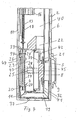
- FIG. 1 to 6 show a cistern 2 in which a drain valve 1 is attached.
- the drain valve 1 is actuated with an actuating device only indicated in FIG. 2 3, which is arranged behind an inspection opening 36 and the one mechanical, electromagnetic, hydraulic or can be pneumatic actuation.
- the in Fig. 2 latch 31 shown in the position shown in Fig. 3 postponed. This shift takes place against the retroactive one Force of a spring 38.
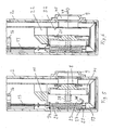
- the drain valve 1 has a main valve 5 and an auxiliary valve 4 on that near a relatively narrow bottom wall 37 of the box body are arranged.
- the main valve 5 has a piston 8, on which a Sealing flange 21 is arranged, which has a valve seat 32 cooperates.
- the piston 8 is horizontal in a valve housing 11 displaceable and in relation to this with an outer circumferential sealing ring 24 sealed.
- a back 39 of the Piston 8 faces a chamber 23, which in FIG Opening 33 of the housing 11 with an interior 40 of the cistern 2 is connected. When the cistern is full is in the Room 40 and room 23 rinse water.
- the interior 40 is also via a passage 22 of the housing 11 with a space 41 connected.
- a front 42 of the piston 8 is this space 41 facing.
- the position of the piston according to FIG. 4 prevails the same water pressure in both rooms 23 and 41.
- a compression spring 28 which on a rear wall 43 of the housing 11th is supported, the piston 8 in that shown in Fig. 4 Position held.
- the main valve 5 is as can be seen closed.
- the auxiliary valve 4 has a rod-shaped closure body 26 on a lower sealing flange 27 and an upper sealing flange 34 has.
- a compression spring 29 is shown in FIG. 4 on one Supported web 44 and holds the closure body 26 in the in Fig. 4 position, in which the lower sealing flange 27 rests on a valve seat 20 of a channel 19.
- the channel 19 leads according to FIG. 4 along and to the bottom wall 37 vertically rising overflow pipe 6, which according to FIG has upper overflow opening 7.
- the channel 19 is horizontal Outlet opening 45 of an outlet nozzle 9 connected.
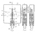
- the valve body 26 with two tie rods 13 and 14 connected, which according to FIGS. 1 to 3 by a lower Float 16 and an upper float 15 passed through are.
- the upper float 15 is in the area of an external thread 17 connected to the pull rod 14.
- the pull rod 14 By turning the pull rod 14 the float 15 can be adjusted in height. in this connection the float 15 is displaceable on two guide rails 12 stored. These rails 12 are on a rear wall 10 of the Cistern body attached.
- the lower float 16 is regarding the pull rod 14 is freely movable in height.
- the lower Float 16 is in the area of an external thread 18 with the pull rod 13 connected. By turning the pull rod 13, the lower one Float 16 can be adjusted in height, this too is slidably guided on the rails 12.
- the float 15 is freely movable. Is the The cistern is filled with rinsing water, so the upper float 15 on the drawbar 14 and the lower float 16 on the drawbar 13 an upward force. Because in the rest position both tie rods 14 and 13 each fixed with a bolt 31 are at rest by these forces Drawbars 13 and 14 are not moving. 2 is only the bolt 31 visible, which engages with the pull rod is. As can be seen, the latch 31 engages in a constriction 35 of the pull rod 13. Another bar, not shown here is engaged with the tie rod 14. Both bars are apart can be operated independently.
- drain valve 1 The operation of the drain valve 1 is explained below.
- the cistern 2 In the starting position, the cistern 2 is filled with rinsing water. The filling takes place in a manner known per se with a fill valve not shown here.
- the piston 8 and the closure body 26 are in the positions shown in FIG. 4.
- the main valve 5 and the auxiliary valve 4 are thus closed.
- the pull rod 13 unlocked.
- the corresponding bolt 31 is shown in FIG. 2 moved to the right. This can be mechanical, electromagnetic, hydraulic or done pneumatically.
- buoyancy the lower float 16 now moves the tie rod 13 above and thereby the closure body 26 is in the in Fig. 5th shown upper position moves.
- the sealing flange 34 lies here as can be seen on the housing 11 and closes the passage 33.
- the sealing flange 27 is now lifted off the valve seat 20 and the space 23 is connected to the channel 19 at the valve seat 20.
- water now flows from space 23 into the Channel 19. This reduces the static pressure in chamber 23.
- the pressure in the chamber 41 is maintained due to the pressure difference of the pistons 8 in FIG moved right to left, the spring 28 being tensioned.
- the Sealing flange 21 is thus lifted from the valve seat 32 and that Main valve 5 opened.
- the water in the cistern flows through the passage 22 into the outlet opening 45 and leaves it in Direction of arrow 47.
- the water flows directly into the rinsing channel a toilet bowl, not shown here.
- the pull rod 14 is unlocked.
- the Auxiliary valve 4 and main valve 5 open as above explained.
- the level of the rinsing water is now about the height of the line 48 shown in broken lines in FIG. 1, this is omitted the buoyancy of the upper float 15 and the pull rod 14 moves down and is automatically by the corresponding Bolt 31 locked.
- the closure body 26 thereby moves in the position shown in Fig. 4. That is the passage 33 open and through this, the chamber 23 from the interior 40 filled with water. This eliminates the pressure difference and the piston 8 through the compression springs 28 in the in Fig. 4th shown locking position moves.
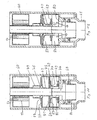
- the drain valve 50 is shown in FIGS. 7 to 12 explained.
- the drain valve 50 is attached to the bottom 66 of a cistern 51 and according to FIG. 10 has a vertically projecting downward Outlet spout 86, which is only partially in one here visible flushing sheet 65 opens out and opposite this with a circumferential lip seal 67 is sealed.
- a valve seat 68 is arranged, which with a piston 70 Main valve 54 forms.
- the piston 70 is in a valve housing 61 limited vertical displacement, with a circumferential sealing lip 71 on the inside on a cylindrical wall 61a of the valve housing 61 slides along.
- a sealing flange 69 is arranged, which is connected to the valve seat 68 cooperates.
- the auxiliary valve 53 with a closure body 63 forms. 11
- the sealing flange 73 has an inner circular shape Breakthrough 74 on that with an annular chamber 82 is connected. This chamber 82 is down to the neck 86 open.
- a circumferential collar is on the closure body 63 75 integrally formed, according to 53 with the auxiliary valve closed Fig. 10 rests on the sealing flange 73.
- the collar 75 is on the top a guide member 79 attached, which in Fig. 11 in a Opening 78 of a cover 77 protrudes and the openings on the circumference 79a owns. 10, the chamber 85 is thus also an upper chamber 72 of the valve housing 61 connected.
- the the corresponding locking bar 57 is not here shown.
- the two bars are against the retroactive one Force of a spring 88 by means of an actuating device 52 in an unlocked position slidable.
- the actuator 52 can be mechanical, electromagnetic, hydraulic or a pneumatic or other device his. 8 is the latch 55 shown here after can be moved to the right. This also does not apply to the others here bolt shown, which is in engagement with the tie rod 57.
- Both floats 59 and 60 are vertical independently of one another slidably and concentrically guided on the closure body 63.
- the lower float 60 is with the rod 56 and the upper one Float 59 is connected to the rod 57.
- Both swimmers 59 and 60 are each adjustable, for example screwable with of the respective rod 56 or 57 connected.
- a web 62 At the top of the Closure body 63 is arranged a web 62, which according to 8 and 9, the rods 56 and 57 each over one shoulder 89 embraces.
- valve 50 The operation of the valve 50 is explained in more detail below.
- FIG. 10 shows the drain valve 50 in the starting position.
- the cistern 51 is up to a level 91 Rinse water filled.
- the main valve 54 as well as the auxiliary valve 53 are closed.
- the rod 56 is so unlocked.
- the lower float 60 connected to the rod 56 due to its buoyancy, wherein said shoulder 89 engages the web 62 and thus the The closing body 63 of the auxiliary valve 53 lifts.
- the collar 75 is thereby changed from the sealing flange 73 to that shown in FIG. 11 Position raised. This will clear passage 74 chamber 72 water flows down through chamber 82 in the nozzle 86 away.
- the pressure in chamber 72 is thereby reduced. In the lower chamber 83, however, continues to exist static pressure of the rinse water 90, since this space 83 over the Window 84 is connected to this room 85. Because the pressure in the lower chamber 83 is larger than in the upper chamber 72 by this differential pressure, the piston 70 into that shown in FIG Position raised.
- the main valve 54 is thus opened and the rinse water 90 can according to the arrows 92 by the Window 84 in the nozzle 86 and finally in the flushing bow 65 flow.
- the opening 78 in the lid 77 is now open again and rinse water flows into space 72 and causes pressure equalization with the space 83.
- the closure body 63 is now through the gravity is brought into the starting position and by the Water pressure held in this.
- the spring 88 Rod 56 automatically locked again.
- the main valve 54 and the auxiliary valve 53 are thus closed and the one not shown here Inlet valve fills the cistern up to the level 91 on.
- the cistern 51 is thus for further flushing ready again.
- the rod 57 is unlocked.
- the top swimmer 59 now becomes active and moves the rod 57 and with it the Closure body 63 upwards.
- the flush is triggered.
- the level 91 of the rinse water drops 90 according to FIG. 7 approximately to the level of level 91a, the falls Buoyancy of the upper float 59 away and this becomes one Weight.
- the opening 78 free and a static pressure builds up in the chamber 72 which moves the piston 70 on the valve seat 68.
- the main valve 54 and the auxiliary valve 53 locked.
- the closing movement of the main valve 54 is shown in In this case, the partial flush is triggered prematurely. Corresponding only leaves a subset of the rinse water 90 den Cistern 51. This subset can be moved by moving the upper Float 59 can be set. For this purpose, the rod 57 is used, for example rotated and the upper float 59 upwards or screwed down. Here, as mentioned above, it is on the closure body 63 out. In this case too, as explained above, the closing process of the main valve 54 is damped since the piston 70 due to a pressure difference down on the Valve seat 68 is moved.
Landscapes
- Health & Medical Sciences (AREA)
- Life Sciences & Earth Sciences (AREA)
- Engineering & Computer Science (AREA)
- Hydrology & Water Resources (AREA)
- Public Health (AREA)
- Water Supply & Treatment (AREA)
- Float Valves (AREA)
- Sanitary Device For Flush Toilet (AREA)
- Self-Closing Valves And Venting Or Aerating Valves (AREA)
- Fluid-Driven Valves (AREA)
Abstract
Description
Die Erfindung betrifft ein Ablaufventil für einen Spülkasten, mit einem Hilfsventil, das einen Verschlusskörper aufweist, nach dessen Betätigung der statische Druck des Spülwassers ein selbsttätiges Öffnen des Hauptventils bewirkt.The invention relates to a drain valve for a cistern, with an auxiliary valve, which has a closure body, after its actuation is the static pressure of the rinse water automatic opening of the main valve causes.
Ein Ablaufventil dieser Art ist im Stand der Technik aus der DE 2609138 bekannt geworden. Bei diesem ist der Verschlusskörper des Hauptventils ein auf- und abbewegbar geführter Kolben. Am Kolben ist ein Dichtflansch angebracht, der bei gefülltem Spülkasten aufgrund des statischen Druckes auf dem Ventilsitz des Hauptventils aufliegt. Eine obere Seite des Dichtflansches bietet sich einem Zylinderraum dar, der nach einer Betätigung des Hilfsventils vom Wasserdruck entlastet wird. Dieses Ablaufventil hat den Vorteil, dass es mit einem vergleichsweise geringen Kraftaufwand betätigt werden kann. Zur Auslösung eines Spülvorganges wird auf den Verschlusskörper des Hilfsventils ein Druck ausgeübt, wodurch das Hilfsventil geöffnet wird. Dadurch fällt der Druck im genannten Zylinderraum und infolge des eintretenden Druckgefälles und aufgrund einer Auftriebskraft der in Hohlräumen des Kolbens befindlichen Luft wird der Kolben angehoben und damit das Hauptventil geöffnet. Im Spülkasten vorhandenes Wasser kann damit ungehindert aus dem Spülkasten abfliessen.A drain valve of this type is known from the prior art DE 2609138 become known. This is the closure body of the main valve an up and down movable piston. At the Piston is attached to a sealing flange, which is when the cistern is full due to the static pressure on the valve seat of the Main valve rests. An upper side of the sealing flange offers is a cylinder space, which after actuation of the Auxiliary valve is relieved of the water pressure. This drain valve has the advantage that it is comparatively low Force can be operated. To trigger a rinsing process is a pressure on the closure body of the auxiliary valve exercised, which opens the auxiliary valve. This makes it fall the pressure in the named cylinder space and as a result of the entering Pressure drop and due to a buoyancy of the cavities air in the piston, the piston is lifted and so that the main valve is open. Water in the cistern can flow freely from the cistern.
Seit längerem sind nun Spülkästen üblich, die auch eine Spülung mit einer Teilmenge des Spülwassers, beispielsweise mit 6 Liter ermöglichen. Damit lässt sich in grossem Umfang Wasser sparen. Der Erfindung liegt nun die Aufgabe zugrunde, das genannte Ablaufventil so weiterzubilden, dass mit diesem auch eine Teilspülung möglich ist. Das Ventil soll trotzdem einen einfachen Aufbau besitzen sowie funktionssicher und wartungsfreundlich sein.Cisterns have also been in use for a long time, which also include flushing with a portion of the rinse water, for example 6 liters enable. This saves water on a large scale. The invention is based on the object, the drain valve so that a partial rinse with this is possible. The valve should still have a simple structure own as well as be reliable and easy to maintain.
Die Aufgabe ist gemäss Anspruch 1 gelöst. Die Steuerung des
Hilfsventils mit einem Schwimmer ermöglicht ein Schliessen dieses
Hilfsventils in Abhängigkeit mit dem Wasserstand im Spülkasten
und damit eine Teilspülung. Vorzugsweise sind in einer
Zweimengenspülung zwei Schwimmer vorgesehen, die in unterschiedlichen
Höhen angeordnet sind. Mit dem unteren Schwimmer wird eine
Vollspülung und mit dem oberen Schwimmer eine Teilspülung gesteuert.
Die Höhe des oberen Schwimmers bestimmt die Menge des
Spülwassers bei der Teilspülung. Ist dieser obere Schwimmer in
seiner Höhe verstellbar, so kann die gewünschte Teilmenge einfach
und gleichzeitig genau eingestellt werden.The object is achieved according to
Ein wesentlicher Vorteil des erfindungsgemässen Ablaufventils wird dahin gesehen, dass das Schliessgeräusch bei einer Teilspülung wesentlich kleiner ist als bei den bisherigen Spülkästen, die eine Teilspülung ermöglichen. Beim erfindungsgemässen Ablaufventil ist der bisher sehr störende Schlag beim Schliessen des Hauptventils wesentlich gedämpft, da der Verschlusskörper des Hauptventils durch einen Differenzdruck des Wassers bewegt wird und sich somit vollständig im Wasser befindet. Der Ventilkörper kann somit nicht schlagartig auf den Ventilsitz auftreffen.A major advantage of the drain valve according to the invention is seen there that the closing noise during a partial flush is significantly smaller than the previous cisterns, that allow a partial rinse. In the drain valve according to the invention is the very annoying blow when closing of the main valve is significantly dampened because the closure body of the main valve is moved by a differential pressure of the water and is therefore completely in the water. The valve body can therefore not suddenly hit the valve seat.
Eine weitere Verminderung des Spülgeräusches kann dann erreicht werden, wenn der Abgang des Spülkastens horizontal erfolgt. Der Ausgang ist damit direkt und ein Spülbogen, in dem üblicherweise Geräusche entstehen, kann vermieden werden.A further reduction in the flushing noise can then be achieved if the cistern outlet is horizontal. The The exit is direct and a flushing bow, in which usually Noises can be avoided.
Nach einer Weiterbildung der Erfindung ist wenigstens eine Zugstange vorgesehen, die mit dem Ventilkörper des Hilfsventils verbunden ist. An dieser Zugstange ist ein Schwimmer angeordnet und mittels eines Riegels oder einer anderen Sperrvorrichtung ist diese Zugstange fixiert. Durch Entriegeln kann nun die Zugstange freigegeben und eine Spülung ausgelöst werden. Die Verschiebung kann mit geringer Kraft erfolgen und ermöglicht eine mechanische, elektromagnetische oder pneumatische Auslösung. Aufgrund der geringen erforderlichen Leistung ist eine Auslösung mit Batteriebetrieb möglich.According to a development of the invention, there is at least one tie rod provided with the valve body of the auxiliary valve connected is. A float is arranged on this tie rod and by means of a latch or other locking device this tie rod is fixed. The pull rod can now be unlocked released and a flush is triggered. The postponement can be done with little force and enables a mechanical, electromagnetic or pneumatic release. Due to the low power required is a trigger possible with battery operation.
Weitere vorteilhafte Merkmale ergeben sich aus den abhängigen Patentansprüchen, der nachfolgenden Beschreibung sowie der Zeichnung.Further advantageous features result from the dependent ones Claims, the following description and the Drawing.
Zwei Ausführungsbeispiele der Erfindung werden nachfolgend anhand der Zeichnung näher erläutert. Es zeigen:
- Fig. 1
- ein Schnitt durch einen Spülkasten mit einem erfindungsgemässen Ablaufventil entlang der Linie I-I der Fig. 2.,
- Fig. 2
- ein Schnitt durch den Spülkasten gemäss Fig. 1 entlang der Linie II-II der Fig. 1,
- Fig. 3
- ein Schnitt gemäss Fig. 2, jedoch bei geöffnetem Ablaufventil,
- Fig. 4-6
- Teilschnitte durch den Spülkasten zur Erläuterung der Arbeitsweise des Ablaufventils,
- Fig. 7
- ein Schnitt durch einen Spülkasten mit einer Variante des erfindungsgemässen Ablaufventils,
- Fig. 8
- ein Schnitt durch den Spülkasten entlang der Linie VIII-VIII der Fig. 7,
- Fig. 9
- ein Schnitt entsprechend Fig. 8, jedoch bei geöffnetem Hilfsventil und
- Fig. 10-12
- Teilschnitte durch den Spülkasten gemäss Fig. 7 zur Erläuterung der Arbeitsweise des Ablaufventils.
- Fig. 1
- 2 shows a section through a cistern with a drain valve according to the invention along the line II in FIG. 2,
- Fig. 2
- 2 shows a section through the cistern according to FIG. 1 along the line II-II of FIG. 1,
- Fig. 3
- 2, but with the drain valve open,
- Fig. 4-6
- Partial sections through the cistern to explain the operation of the drain valve,
- Fig. 7
- 2 shows a section through a cistern with a variant of the drain valve according to the invention,
- Fig. 8
- a section through the cistern along the line VIII-VIII of Fig. 7,
- Fig. 9
- a section corresponding to FIG. 8, but with the auxiliary valve open and
- Fig. 10-12
- Partial sections through the cistern according to FIG. 7 to explain the operation of the drain valve.
Die Fig. 1 bis 6 zeigen einen Spülkasten 2, in dem ein Ablaufventil
1 befestigt ist. Die Betätigung des Ablaufventils 1 erfolgt
mit einer in Fig. 2 lediglich angedeuteten Betätigungsvorrichtung
3, die hinter einer Revisionsöffnung 36 angeordnet ist
und die eine mechanische, elektromagnetische, hydraulische oder
pneumatische Betätigung sein kann. Zur Spülauslösung wird der in
Fig. 2 gezeigte Riegel 31 in die in Fig. 3 gezeigte Stellung
verschoben. Diese Verschiebung erfolgt gegen die rückwirkende
Kraft einer Feder 38.1 to 6 show a
Das Ablaufventil 1 weist ein Hauptventil 5 sowie ein Hilfsventil
4 auf, die in der Nähe einer vergleichsweise schmalen Bodenwandung
37 des Kastenkörpers angeordnet sind. Wie insbesondere Fig.
4 zeigt, weist das Hauptventil 5 einen Kolben 8 auf, an dem ein
Dichtflansch 21 angeordnet ist, welcher mit einem Ventilsitz 32
zusammenarbeitet. Der Kolben 8 ist in einem Ventilgehäuse 11 horizontal
verschieblich und gegenüber diesem mit einem äusseren
umlaufenden Dichtungsring 24 abgedichtet. Eine Rückseite 39 des
Kolbens 8 ist einer Kammer 23 zugewandt, die in Fig. 4 über eine
Öffnung 33 des Gehäuses 11 mit einem Innenraum 40 des Spülkastens
2 verbunden ist. Bei gefülltem Spülkasten befindet sich im
Raum 40 als auch im Raum 23 Spülwasser. Der Innenraum 40 ist zudem
über einen Durchgang 22 des Gehäuses 11 mit einem Raum 41
verbunden. Eine Vorderseite 42 des Kolbens 8 ist diesem Raum 41
zugewandt. Bei der Stellung des Kolbens gemäss Fig. 4 herrscht
in den beiden Räumen 23 und 41 der gleiche Wasserdruck. Mittels
einer Druckfeder 28, die an einer Rückwand 43 des Gehäuses 11
abgestützt ist, wird der Kolben 8 in der in Fig. 4 gezeigten
Stellung gehalten. In dieser ist das Hauptventil 5 wie ersichtlich
geschlossen.The
Das Hilfsventil 4 weist einen stabförmigen Verschlusskörper 26
auf, der einen unteren Dichtflansch 27 sowie einen oberen Dichtflansch
34 aufweist. Eine Druckfeder 29 ist gemäss Fig. 4 an einem
Steg 44 abgestützt und hält den Verschlusskörper 26 in der
in Fig. 4 gezeigten Stellung, in welcher der untere Dichtflansch
27 auf einem Ventilsitz 20 eines Kanals 19 aufliegt. Der Kanal
19 führt gemäss Fig. 4 der Bodenwandung 37 entlang und zu einem
vertikal aufsteigenden Überlaufrohr 6, das gemäss Fig. 2 eine
obere Überlauföffnung 7 aufweist. Der Kanal 19 ist mit einer horizontalen
Auslauföffnung 45 eines Auslaufstutzens 9 verbunden.The
Am oberen Ende ist der Ventilkörper 26 mit zwei Zugstangen 13
und 14 verbunden, die gemäss den Fig. 1 bis 3 durch einen unteren
Schwimmer 16 und einen oberen Schwimmer 15 hindurchgeführt
sind. Der obere Schwimmer 15 ist im Bereich eines Aussengewindes
17 mit der Zugstange 14 verbunden. Durch Drehen der Zugstange
14 kann der Schwimmer 15 in der Höhe verstellt werden. Hierbei
ist der Schwimmer 15 an zwei Führungsschienen 12 verschieblich
gelagert. Diese Schienen 12 sind an einer Rückwand 10 des
Spülkastenkörpers befestigt. Der untere Schwimmer 16 ist bezüglich
der Zugstange 14 in der Höhe frei verschiebbar. Der untere
Schwimmer 16 ist im Bereich eines Aussengewindes 18 mit der Zugstange
13 verbunden. Durch Drehen der Zugstange 13 kann der untere
Schwimmer 16 in der Höhe verstellt werden, wobei auch dieser
an den Schienen 12 verschieblich geführt ist. Bezüglich der
Zugstange 13 ist der Schwimmer 15 frei verschiebbar. Ist der
Spülkasten mit Spülwasser gefüllt, so übt der obere Schwimmer 15
auf die Zugstange 14 und der untere Schwimmer 16 auf die Zugstange
13 eine nach oben wirkende Kraft auf. Da in der Ruhestellung
beide Zugstangen 14 und 13 jeweils mit einem Riegel 31 fixiert
sind, werden in der Ruhestellung durch diese Kräfte die
Zugstangen 13 und 14 nicht bewegt. In der Fig. 2 ist lediglich
der Riegel 31 sichtbar, welcher mit der Zugstange in Eingriff
ist. Wie ersichtlich greift der Riegel 31 in eine Einschnürung
35 der Zugstange 13 ein. Ein weiterer hier nicht gezeigter Riegel
ist mit der Zugstange 14 in Eingriff. Beide Riegel sind voneinander
unabhängig betätigbar.At the upper end is the
Nachfolgend wird die Wirkungsweise des Ablaufventils 1 erläutert.The operation of the
In der Ausgangsstellung ist der Spülkasten 2 mit Spülwasser gefüllt.
Das Füllen erfolgt in an sich bekannter Weise mit einem
hier nicht gezeigten Einfüllventil. Der Kolben 8 und der Verschlusskörper
26 befinden sich in den in Fig. 4 gezeigten Stellungen.
Das Hauptventil 5 und das Hilfsventil 4 sind somit geschlossen.
Zur Auslösung einer Vollspülung wird die Zugstange 13
entriegelt. Dazu wird der entsprechende Riegel 31 in Fig. 2 nach
rechts bewegt. Dieser kann mechanisch, elektromagnetisch, hydraulisch
oder pneumatisch geschehen. Durch die Auftriebskraft
des unteren Schwimmers 16 bewegt sich nun die Zugstange 13 nach
oben und dadurch wird der Verschlusskörper 26 in die in Fig. 5
gezeigte obere Stellung bewegt. Der Dichtflansch 34 liegt hier,
wie ersichtlich am Gehäuse 11 an und verschliesst den Durchgang
33. Der Dichtflansch 27 ist nun vom Ventilsitz 20 abgehoben und
der Raum 23 ist am Ventilsitz 20 mit dem Kanal 19 verbunden. In
Richtung des Pfeiles 46 strömt nun Wasser aus dem Raum 23 in den
Kanal 19. Dadurch sinkt der statische Druck in der Kammer 23. Da
gleichzeitig der Druck in der Kammer 41 erhalten bleibt, wird
aufgrund der Druckdifferenz der Kolben 8 in der Fig. 5 von
rechts nach links bewegt, wobei die Feder 28 gespannt wird. Der
Dichtflansch 21 wird damit vom Ventilsitz 32 abgehoben und das
Hauptventil 5 geöffnet. Das Wasser des Spülkastens strömt durch
den Durchgang 22 in die Auslauföffnung 45 und verlässt diese in
Richtung des Pfeiles 47. Das Wasser fliesst direkt in den Spülkanal
einer hier nicht gezeigten Klosettschüssel. In the starting position, the
Ist der Wasserstand soweit gesunken, dass der Schwimmer 16 sich
nach unten bewegt, wird der Verschlusskörper 26 unter Mithilfe
der Feder 29 wieder in die in Fig. 4 gezeigte Ausgangsstellung
bewegt. Durch die nun wieder geöffnete Öffnung 33 fliesst das
Wasser wieder in den Raum 23 und bewirkt einen Druckausgleich
mit dem Raum 41. Die gespannte Druckfeder 28 kann so den Kolben
8 wieder in die Ausgangsstellung bringen. Das Hauptventil 5 und
das Hilfsventil 4 sind somit geschlossen und mit dem hier nicht
gezeigten Einfüllventil wird der Spülkasten wieder gefüllt. Die
Zugstange 13 wird mit dem Riegel 31 selbsttätig verriegelt, sodass
der Spülkasten nun für eine weitere Spülung bereit ist.Has the water level dropped so far that the
Für eine Teilspülung, bei der beispielsweise lediglich mit drei
Liter Wasser gespült wird, wird die Zugstange 14 entriegelt. Das
Hilfsventil 4 und das Hauptventil 5 öffnen sich wie bereits oben
erläutert. Befindet sich nun das Niveau des Spülwassers etwa auf
der Höhe der in Fig. 1 gestrichelt gezeigten Linie 48, so entfällt
der Auftrieb des oberen Schwimmers 15 und die Zugstange 14
bewegt sich nach unten und wird selbsttätig vom entsprechenden
Riegel 31 verriegelt. Der Verschlusskörper 26 bewegt sich dadurch
in die in Fig. 4 gezeigte Stellung. Damit ist der Durchgang
33 offen und durch diesen wird die Kammer 23 aus dem Innenraum
40 mit Wasser gefüllt. Die Druckdifferenz wird damit aufgehoben
und der Kolben 8 durch die Druckfedern 28 in die in Fig. 4
gezeigte Verschlussstellung bewegt. Das sich während dieser Bewegung
sowohl in der Kammer 41 als auch in der Kammer 23 Wasser
befindet, erfolgt diese Schliessbewegung nicht schlagartig und
somit geräuschgedämpft. Die Verschlussstellung wird durch den
Wasserdruck gehalten, da die beaufschlagte Fläche der Seite 39
grösser ist als diejenige der Frontseite 42. Auch nach dieser
Teilspülung wird selbstverständlich der Spülkasten wieder durch
das Füllventil nachgefüllt. For a partial rinse, for example with only three
Liters of water is flushed, the
Nachfolgend wird das Ablaufventil 50 gemäss den Fig. 7 bis 12
erläutert.The
Das Ablaufventil 50 ist am Boden 66 eines Spülkastens 51 befestigt
und weist gemäss Fig. 10 einen vertikal nach unten ragenden
Auslaufstutzen 86 auf, der in einen hier nur teilweise
sichtbaren Spülbogen 65 mündet und gegenüber diesem mit einer
umlaufenden Lippendichtung 67 abgedichtet ist. Über dem Stutzen
86 ist ein Ventilsitz 68 angeordnet, der mit einem Kolben 70 ein
Hauptventil 54 bildet. Der Kolben 70 ist in einem Ventilgehäuse
61 begrenzt vertikal verschiebbar, wobei eine umlaufende Dichtlippe
71 innenseitig an einer zylindrischen Wandung 61a des Ventilgehäuses
61 entlang gleitet. Am unteren Ende des Kolbens 70
ist ein Dichtflansch 69 angeordnet, der mit dem Ventilsitz 68
zusammenarbeitet. Im unteren Teil der Wandung 61a sind Fenster
84 ausgespart, welche einen oberen Raum 85 des Spülkastens 51
mit einem Innenraum 83 des Ventilgehäuses 61 verbinden.The
Am oberen Ende des Kolbens 70 ist ein weiterer Dichtflansch 73
angeordnet, der mit einem Verschlusskörper 63 ein Hilfsventil 53
bildet. Der Dichtflansch 73 weist gemäss Fig. 11 einen innenkreisförmigen
Durchbruch 74 auf, der mit einer ringförmigen Kammer
82 verbunden ist. Diese Kammer 82 ist nach unten zum Stutzen
86 hin offen. Am Verschlusskörper 63 ist ein umlaufender Kragen
75 angeformt, der bei geschlossenem Hilfsventil 53 gemäss
Fig. 10 auf dem Dichtflansch 73 aufliegt. Am Kragen 75 ist oberseitig
ein Führungsteil 79 angebracht, das in Fig. 11 in eine
Öffnung 78 eines Deckels 77 hineinragt und der am Umfang Durchbrüche
79a besitzt. In der Fig. 10 ist somit die Kammer 85 mit
einer oberen Kammer 72 des Ventilgehäuses 61 verbunden. In der
Fig. 10 herrscht somit in den Kammern 72 und 84 der gleiche Wasserdruck
wie im Raum 85. Am Verschlusskörper 63 sind konzentrisch
und in unterschiedlichen Höhen zwei becherförmige nach
unten offene Schwimmer 59 und 60 angeordnet. Der untere Schwimmer
60 ist mit einer Stange 56 verbunden, beispielsweise mit dem
in Fig. 11 angedeuteten Gewinde 87. Mit dem oberen Schwimmer 59
ist die Stange 56 jedoch nicht verbunden. Der obere Schwimmer 59
ist hingegen mit einer zweiten Stange 57 verbunden, beispielsweise
ebenfalls verschraubt. Beide Stangen 56 und 57 sind somit
jeweils mit einem Schwimmer 59 bzw. 60 verbunden. Am oberen Ende
weisen die Stangen 56 und 57 jeweils eine Einschnürung 58 auf,
in die jeweils ein Riegel eingreift. In der Fig. 8 ist lediglich
der Riegel 55 gezeigt, welcher die Stange 56 verriegelt. Der
entsprechende die Stange 57 verriegelnde Riegel ist hier nicht
gezeigt. Die beiden Riegel sind jeweils gegen die rückwirkende
Kraft einer Feder 88 mittels einer Betätigungsvorrichtung 52 in
eine entriegelte Stellung verschiebbar. Die Betätigungsvorrichtung
52 kann eine mechanische, eine elektromagnetische, hydraulische
oder eine pneumatische oder auch eine sonstige Vorrichtung
sein. In der Fig. 8 ist der hier gezeigte Riegel 55 nach
rechts verschiebbar. Dies gilt auch für den weiteren hier nicht
gezeigten Riegel, der mit der Zugstange 57 in Eigriff ist.At the upper end of the
Beide Schwimmer 59 und 60 sind unabhängig voneinander vertikal
verschieblich und konzentrisch am Verschlusskörper 63 geführt.
Der untere Schwimmer 60 ist mit der Stange 56 und der obere
Schwimmer 59 ist mit der Stange 57 verbunden. Beide Schwimmer 59
und 60 sind jeweils verstellbar, beispielsweise schraubbar mit
der jeweiligen Stange 56 bzw. 57 verbunden. Am oberen Ende des
Verschlusskörpers 63 ist ein Steg 62 angeordnet, welcher gemäss
den Fig. 8 und 9 die Stangen 56 und 57 jeweils über einer Schulter
89 umgreift.Both floats 59 and 60 are vertical independently of one another
slidably and concentrically guided on the
Nachfolgend wird die Arbeitsweise des Ventils 50 näher erläutert. The operation of the
Die Fig. 10 zeigt das Ablaufventil 50 in der Ausgangsstellung.
Der Spülkasten 51 ist gemäss Fig. 7 bis zu einem Niveau 91 mit
Spülwasser gefüllt. Das Hauptventil 54 als auch das Hilfsventil
53 sind geschlossen. Zur Auslösung einer Vollspülung wird
nun der Riegel 55 von der in Fig. 8 gezeigten Stellung in die in
Fig. 9 gezeigte Stellung verschoben. Die Stange 56 ist damit
entriegelt. Der untere Schwimmer 60, der mit der Stange 56 verbunden
ist, bewegt diese aufgrund seines Auftriebes nach oben,
wobei die genannte Schulter 89 am Steg 62 angreift und damit den
Verschusskörper 63 des Hilfsventils 53 anhebt. Der Kragen 75
wird dadurch vom Dichtflansch 73 in die in Fig. 11 gezeigte
Stellung angehoben. Dadurch wird der Durchgang 74 frei und aus
der Kammer 72 fliesst Wasser nach unten durch die Kammer 82 in
den Stutzen 86 weg. Der Druck in der Kammer 72 wird dadurch erniedrigt.
In der unteren Kammer 83 besteht aber weiterhin der
statische Druck des Spülwassers 90, da dieser Raum 83 über die
Fenster 84 mit diesem Raum 85 verbunden ist. Da der Druck in der
unteren Kammer 83 grösser ist als in der oberen Kammer 72, wird
durch diesen Differenzdruck der Kolben 70 in die in Fig. 12 gezeigte
Stellung angehoben. Das Hauptventil 54 wird damit geöffnet
und das Spülwasser 90 kann gemäss den Pfeilen 92 durch die
Fenster 84 in den Stutzen 86 und schliesslich in den Spülbogen
65 fliessen. Die Öffnung 78 im Deckel 77 ist nun wieder offen
und Spülwasser strömt in den Raum 72 und bewirkt einen Druckausgleich
mit dem Raum 83. Der Verschlusskörper 63 wird nun durch
die Schwerkraft in die Ausgangsstellung gebracht und durch den
Wasserdruck in dieser gehalten. Durch die Feder 88 wird die
Stange 56 selbsttätig wieder verriegelt. Das Hauptventil 54 und
das Hilfsventil 53 sind damit geschlossen und das hier nicht gezeigte
Einlassventil füllt den Spülkasten wieder bis zum Niveau
91 auf. Der Spülkasten 51 ist damit für eine weitere Spülung
wieder bereit. 10 shows the
Zur Auslösung einer Teilspülung, beispielsweise mit drei Litern
Spülwasser, wird die Stange 57 entriegelt. Der obere Schwimmer
59 wird nun aktiv und bewegt die Stange 57 und mit dieser den
Verschlusskörper 63 nach oben. Damit wird, wie oben erläutert,
die Spülung ausgelöst. Fällt nun das Niveau 91 des Spülwassers
90 gemäss Fig. 7 etwa auf die Höhe des Niveaus 91a, so fällt der
Auftrieb des oberen Schwimmers 59 weg und dieser wird zu einem
Gewicht. Dieses lastet über dem Verschlusskörper 63 auf dem Kolben
70, der nach unten bewegt wird. Gleichzeitig wird die Öffnung
78 frei und in der Kammer 72 baut sich ein statischer Druck
auf, welcher den Kolben 70 auf dem Ventilsitz 68 bewegt.
Schliesslich sind das Hauptventil 54 als auch das Hilfsventil 53
verschlossen. Die Schliessbewegung des Hauptventils 54 wird in
diesem Fall der Teilspülung somit vorzeitig ausgelöst. Entsprechend
verlässt lediglich eine Teilmenge des Spülwassers 90 den
Spülkasten 51. Diese Teilmenge kann durch Verschieben des oberen
Schwimmers 59 eingestellt werden. Dazu wird die Stange 57 beispielsweise
gedreht und der obere Schwimmer 59 nach oben bzw.
nach unten geschraubt. Hierbei ist er, wie oben erwähnt, am Verschlusskörper
63 geführt. Auch in diesem Fall ist, wie oben erläutert,
der Schliessvorgang des Hauptventils 54 gedämpft, da
der Kolben 70 aufgrund einer Druckdifferenz nach unten auf dem
Ventilsitz 68 bewegt wird.To trigger a partial flush, for example with three liters
Rinse water, the
Claims (14)
Applications Claiming Priority (2)
| Application Number | Priority Date | Filing Date | Title |
|---|---|---|---|
| CH11702001 | 2001-06-26 | ||
| CH11702001 | 2001-06-26 |
Publications (3)
| Publication Number | Publication Date |
|---|---|
| EP1270831A2 true EP1270831A2 (en) | 2003-01-02 |
| EP1270831A3 EP1270831A3 (en) | 2004-06-16 |
| EP1270831B1 EP1270831B1 (en) | 2006-09-27 |
Family
ID=4561202
Family Applications (1)
| Application Number | Title | Priority Date | Filing Date |
|---|---|---|---|
| EP02405472A Expired - Lifetime EP1270831B1 (en) | 2001-06-26 | 2002-06-11 | Discharge valve for a cistern |
Country Status (3)
| Country | Link |
|---|---|
| EP (1) | EP1270831B1 (en) |
| AT (1) | ATE340898T1 (en) |
| DE (1) | DE50208234D1 (en) |
Cited By (2)
| Publication number | Priority date | Publication date | Assignee | Title |
|---|---|---|---|---|
| WO2006043205A1 (en) * | 2004-10-18 | 2006-04-27 | Eczacibasi Yapi Gereçleri Sanayi Ve Ticaret A.S. | Stoppered discharge valve for cistern |
| EP1719844A1 (en) | 2005-05-06 | 2006-11-08 | Geberit Technik Ag | Flush valve for a flush cistern |
Families Citing this family (1)
| Publication number | Priority date | Publication date | Assignee | Title |
|---|---|---|---|---|
| DE202013010538U1 (en) | 2012-12-12 | 2014-02-04 | Mepa-Pauli Und Menden Gmbh | drain valve |
Citations (3)
| Publication number | Priority date | Publication date | Assignee | Title |
|---|---|---|---|---|
| US4176821A (en) * | 1976-03-05 | 1979-12-04 | Georg Rost & Sohne | Pilot-operated valve assembly |
| US4557000A (en) * | 1982-09-15 | 1985-12-10 | Georg Rost | Toilet-tank discharge valve |
| WO2002077377A2 (en) * | 2001-03-26 | 2002-10-03 | Geberit Technik Ag | Flushing device for a lavatory |
-
2002
- 2002-06-11 AT AT02405472T patent/ATE340898T1/en not_active IP Right Cessation
- 2002-06-11 EP EP02405472A patent/EP1270831B1/en not_active Expired - Lifetime
- 2002-06-11 DE DE50208234T patent/DE50208234D1/en not_active Expired - Lifetime
Patent Citations (3)
| Publication number | Priority date | Publication date | Assignee | Title |
|---|---|---|---|---|
| US4176821A (en) * | 1976-03-05 | 1979-12-04 | Georg Rost & Sohne | Pilot-operated valve assembly |
| US4557000A (en) * | 1982-09-15 | 1985-12-10 | Georg Rost | Toilet-tank discharge valve |
| WO2002077377A2 (en) * | 2001-03-26 | 2002-10-03 | Geberit Technik Ag | Flushing device for a lavatory |
Cited By (3)
| Publication number | Priority date | Publication date | Assignee | Title |
|---|---|---|---|---|
| WO2006043205A1 (en) * | 2004-10-18 | 2006-04-27 | Eczacibasi Yapi Gereçleri Sanayi Ve Ticaret A.S. | Stoppered discharge valve for cistern |
| EP1719844A1 (en) | 2005-05-06 | 2006-11-08 | Geberit Technik Ag | Flush valve for a flush cistern |
| US7353547B2 (en) | 2005-05-06 | 2008-04-08 | Geberit Technik Ag | Discharge valve for a flushing cistern |
Also Published As
| Publication number | Publication date |
|---|---|
| EP1270831A3 (en) | 2004-06-16 |
| EP1270831B1 (en) | 2006-09-27 |
| DE50208234D1 (en) | 2006-11-09 |
| ATE340898T1 (en) | 2006-10-15 |
Similar Documents
| Publication | Publication Date | Title |
|---|---|---|
| EP1719844B1 (en) | Flush valve for a flush cistern | |
| EP1507933B1 (en) | Flushing device for a lavatory | |
| EP0722020B1 (en) | Flushing device in a flushing tank | |
| EP0663035A1 (en) | Wc flushing device | |
| CH643622A5 (en) | Drain set for cistern. | |
| DE19501355C2 (en) | Drain fitting for a cistern | |
| DE3133650C2 (en) | ||
| EP1197607B1 (en) | Flushing cistern for a WC | |
| EP1270831B1 (en) | Discharge valve for a cistern | |
| DE10002308C2 (en) | Toilet cistern | |
| EP0737784A1 (en) | Flush valve for a flush cistern | |
| EP1537277A2 (en) | Flushing device comprising a pressurized chamber, evacuation fitting for a flushing device, and system comprising a flushing device and a toilet bowl | |
| DE2820777A1 (en) | Universally effective lavatory flushing cistern - has spring loaded pressure plate dependent on outflow valve control | |
| DE10300931A1 (en) | Operating device for expiration bell of a flushing cistern, has hydraulic lifting device and solenoid valve formed as one unit for moving lifting arm to operate expiration bell | |
| DE2526227A1 (en) | Twin chamber toilet cistern - has separate discharge systems for each chamber with common down or outlet pipe | |
| DE115198C (en) | ||
| EP0859093B1 (en) | Outlet device for a toilet flush tank with selective full or partial flush | |
| DE603730C (en) | Device for dispensing a liquid in an adjustable amount | |
| DE2056490C3 (en) | Elevator flushing device in a toilet bowl for dispensing different amounts of water | |
| DE3153738C2 (en) | Inlet valve for WC tank | |
| DE2626053A1 (en) | DEVICE FOR THE CONVERSION OF A FLUSHBOX OF FIXED VOLUME INTO A FLUSHBOX WITH CHANGEABLE VOLUME | |
| DE2102030C3 (en) | Flushing device, especially for toilets, with a pressurized tank | |
| DE39160C (en) | Locking device for water posts and street fountains | |
| DE1609275A1 (en) | Float-controlled filling valve for toilet cisterns and other liquid containers | |
| DE345039C (en) | Lift cistern for flushing with different amounts of water |
Legal Events
| Date | Code | Title | Description |
|---|---|---|---|
| PUAI | Public reference made under article 153(3) epc to a published international application that has entered the european phase |
Free format text: ORIGINAL CODE: 0009012 |
|
| AK | Designated contracting states |
Kind code of ref document: A2 Designated state(s): AT BE CH CY DE DK ES FI FR GB GR IE IT LI LU MC NL PT SE TR |
|
| AX | Request for extension of the european patent |
Free format text: AL;LT;LV;MK;RO;SI |
|
| PUAL | Search report despatched |
Free format text: ORIGINAL CODE: 0009013 |
|
| AK | Designated contracting states |
Kind code of ref document: A3 Designated state(s): AT BE CH CY DE DK ES FI FR GB GR IE IT LI LU MC NL PT SE TR |
|
| AX | Request for extension of the european patent |
Extension state: AL LT LV MK RO SI |
|
| 17P | Request for examination filed |
Effective date: 20040814 |
|
| AKX | Designation fees paid |
Designated state(s): AT BE CH CY DE DK ES FI FR GB GR IE IT LI LU MC NL PT SE TR |
|
| GRAP | Despatch of communication of intention to grant a patent |
Free format text: ORIGINAL CODE: EPIDOSNIGR1 |
|
| GRAS | Grant fee paid |
Free format text: ORIGINAL CODE: EPIDOSNIGR3 |
|
| GRAA | (expected) grant |
Free format text: ORIGINAL CODE: 0009210 |
|
| AK | Designated contracting states |
Kind code of ref document: B1 Designated state(s): AT BE CH CY DE DK ES FI FR GB GR IE IT LI LU MC NL PT SE TR |
|
| GBT | Gb: translation of ep patent filed (gb section 77(6)(a)/1977) |
Effective date: 20060906 |
|
| PG25 | Lapsed in a contracting state [announced via postgrant information from national office to epo] |
Ref country code: IT Free format text: LAPSE BECAUSE OF FAILURE TO SUBMIT A TRANSLATION OF THE DESCRIPTION OR TO PAY THE FEE WITHIN THE PRESCRIBED TIME-LIMIT;WARNING: LAPSES OF ITALIAN PATENTS WITH EFFECTIVE DATE BEFORE 2007 MAY HAVE OCCURRED AT ANY TIME BEFORE 2007. THE CORRECT EFFECTIVE DATE MAY BE DIFFERENT FROM THE ONE RECORDED. Effective date: 20060927 Ref country code: FI Free format text: LAPSE BECAUSE OF FAILURE TO SUBMIT A TRANSLATION OF THE DESCRIPTION OR TO PAY THE FEE WITHIN THE PRESCRIBED TIME-LIMIT Effective date: 20060927 Ref country code: IE Free format text: LAPSE BECAUSE OF FAILURE TO SUBMIT A TRANSLATION OF THE DESCRIPTION OR TO PAY THE FEE WITHIN THE PRESCRIBED TIME-LIMIT Effective date: 20060927 |
|
| REG | Reference to a national code |
Ref country code: GB Ref legal event code: FG4D Free format text: NOT ENGLISH |
|
| GBT | Gb: translation of ep patent filed (gb section 77(6)(a)/1977) |
Effective date: 20061002 |
|
| REG | Reference to a national code |
Ref country code: CH Ref legal event code: NV Representative=s name: ISLER & PEDRAZZINI AG Ref country code: CH Ref legal event code: EP |
|
| REG | Reference to a national code |
Ref country code: IE Ref legal event code: FG4D Free format text: LANGUAGE OF EP DOCUMENT: GERMAN |
|
| REF | Corresponds to: |
Ref document number: 50208234 Country of ref document: DE Date of ref document: 20061109 Kind code of ref document: P |
|
| PG25 | Lapsed in a contracting state [announced via postgrant information from national office to epo] |
Ref country code: SE Free format text: LAPSE BECAUSE OF FAILURE TO SUBMIT A TRANSLATION OF THE DESCRIPTION OR TO PAY THE FEE WITHIN THE PRESCRIBED TIME-LIMIT Effective date: 20061227 Ref country code: DK Free format text: LAPSE BECAUSE OF FAILURE TO SUBMIT A TRANSLATION OF THE DESCRIPTION OR TO PAY THE FEE WITHIN THE PRESCRIBED TIME-LIMIT Effective date: 20061227 |
|
| PG25 | Lapsed in a contracting state [announced via postgrant information from national office to epo] |
Ref country code: ES Free format text: LAPSE BECAUSE OF FAILURE TO SUBMIT A TRANSLATION OF THE DESCRIPTION OR TO PAY THE FEE WITHIN THE PRESCRIBED TIME-LIMIT Effective date: 20070107 |
|
| PG25 | Lapsed in a contracting state [announced via postgrant information from national office to epo] |
Ref country code: PT Free format text: LAPSE BECAUSE OF FAILURE TO SUBMIT A TRANSLATION OF THE DESCRIPTION OR TO PAY THE FEE WITHIN THE PRESCRIBED TIME-LIMIT Effective date: 20070313 |
|
| REG | Reference to a national code |
Ref country code: IE Ref legal event code: FD4D |
|
| ET | Fr: translation filed | ||
| PLBE | No opposition filed within time limit |
Free format text: ORIGINAL CODE: 0009261 |
|
| STAA | Information on the status of an ep patent application or granted ep patent |
Free format text: STATUS: NO OPPOSITION FILED WITHIN TIME LIMIT |
|
| 26N | No opposition filed |
Effective date: 20070628 |
|
| REG | Reference to a national code |
Ref country code: CH Ref legal event code: PCAR Free format text: ISLER & PEDRAZZINI AG;POSTFACH 1772;8027 ZUERICH (CH) |
|
| PG25 | Lapsed in a contracting state [announced via postgrant information from national office to epo] |
Ref country code: MC Free format text: LAPSE BECAUSE OF NON-PAYMENT OF DUE FEES Effective date: 20070630 |
|
| PG25 | Lapsed in a contracting state [announced via postgrant information from national office to epo] |
Ref country code: GR Free format text: LAPSE BECAUSE OF FAILURE TO SUBMIT A TRANSLATION OF THE DESCRIPTION OR TO PAY THE FEE WITHIN THE PRESCRIBED TIME-LIMIT Effective date: 20061228 |
|
| PG25 | Lapsed in a contracting state [announced via postgrant information from national office to epo] |
Ref country code: CY Free format text: LAPSE BECAUSE OF FAILURE TO SUBMIT A TRANSLATION OF THE DESCRIPTION OR TO PAY THE FEE WITHIN THE PRESCRIBED TIME-LIMIT Effective date: 20060927 Ref country code: LU Free format text: LAPSE BECAUSE OF NON-PAYMENT OF DUE FEES Effective date: 20070611 |
|
| PGFP | Annual fee paid to national office [announced via postgrant information from national office to epo] |
Ref country code: AT Payment date: 20090615 Year of fee payment: 8 |
|
| PG25 | Lapsed in a contracting state [announced via postgrant information from national office to epo] |
Ref country code: TR Free format text: LAPSE BECAUSE OF FAILURE TO SUBMIT A TRANSLATION OF THE DESCRIPTION OR TO PAY THE FEE WITHIN THE PRESCRIBED TIME-LIMIT Effective date: 20060927 |
|
| PGFP | Annual fee paid to national office [announced via postgrant information from national office to epo] |
Ref country code: GB Payment date: 20090618 Year of fee payment: 8 |
|
| PGFP | Annual fee paid to national office [announced via postgrant information from national office to epo] |
Ref country code: BE Payment date: 20090715 Year of fee payment: 8 |
|
| REG | Reference to a national code |
Ref country code: CH Ref legal event code: PUE Owner name: GEBERIT INTERNATIONAL AG Free format text: GEBERIT TECHNIK AG#SCHACHENSTRASSE 77#8645 JONA (CH) -TRANSFER TO- GEBERIT INTERNATIONAL AG#SCHACHENSTRASSE 77#8645 JONA (CH) |
|
| REG | Reference to a national code |
Ref country code: NL Ref legal event code: SD Effective date: 20100304 |
|
| REG | Reference to a national code |
Ref country code: FR Ref legal event code: TP |
|
| BERE | Be: lapsed |
Owner name: *GEBERIT TECHNIK A.G. Effective date: 20100630 |
|
| GBPC | Gb: european patent ceased through non-payment of renewal fee |
Effective date: 20100611 |
|
| PG25 | Lapsed in a contracting state [announced via postgrant information from national office to epo] |
Ref country code: AT Free format text: LAPSE BECAUSE OF NON-PAYMENT OF DUE FEES Effective date: 20100611 |
|
| PG25 | Lapsed in a contracting state [announced via postgrant information from national office to epo] |
Ref country code: BE Free format text: LAPSE BECAUSE OF NON-PAYMENT OF DUE FEES Effective date: 20100630 |
|
| PG25 | Lapsed in a contracting state [announced via postgrant information from national office to epo] |
Ref country code: GB Free format text: LAPSE BECAUSE OF NON-PAYMENT OF DUE FEES Effective date: 20100611 |
|
| REG | Reference to a national code |
Ref country code: DE Ref legal event code: R082 Ref document number: 50208234 Country of ref document: DE Representative=s name: HOEGER, STELLRECHT & PARTNER PATENTANWAELTE, DE Ref country code: DE Ref legal event code: R082 Ref document number: 50208234 Country of ref document: DE Representative=s name: HOEGER, STELLRECHT & PARTNER PATENTANWAELTE MB, DE |
|
| PGFP | Annual fee paid to national office [announced via postgrant information from national office to epo] |
Ref country code: NL Payment date: 20140618 Year of fee payment: 13 Ref country code: CH Payment date: 20140610 Year of fee payment: 13 Ref country code: DE Payment date: 20140619 Year of fee payment: 13 |
|
| PGFP | Annual fee paid to national office [announced via postgrant information from national office to epo] |
Ref country code: FR Payment date: 20140619 Year of fee payment: 13 |
|
| PGFP | Annual fee paid to national office [announced via postgrant information from national office to epo] |
Ref country code: IT Payment date: 20140630 Year of fee payment: 13 |
|
| REG | Reference to a national code |
Ref country code: DE Ref legal event code: R082 Ref document number: 50208234 Country of ref document: DE Representative=s name: HOEGER, STELLRECHT & PARTNER PATENTANWAELTE MB, DE |
|
| REG | Reference to a national code |
Ref country code: DE Ref legal event code: R119 Ref document number: 50208234 Country of ref document: DE |
|
| PG25 | Lapsed in a contracting state [announced via postgrant information from national office to epo] |
Ref country code: IT Free format text: LAPSE BECAUSE OF NON-PAYMENT OF DUE FEES Effective date: 20150611 |
|
| REG | Reference to a national code |
Ref country code: CH Ref legal event code: PL |
|
| REG | Reference to a national code |
Ref country code: NL Ref legal event code: MM Effective date: 20150701 |
|
| REG | Reference to a national code |
Ref country code: FR Ref legal event code: ST Effective date: 20160229 |
|
| PG25 | Lapsed in a contracting state [announced via postgrant information from national office to epo] |
Ref country code: LI Free format text: LAPSE BECAUSE OF NON-PAYMENT OF DUE FEES Effective date: 20150630 Ref country code: NL Free format text: LAPSE BECAUSE OF NON-PAYMENT OF DUE FEES Effective date: 20150701 Ref country code: DE Free format text: LAPSE BECAUSE OF NON-PAYMENT OF DUE FEES Effective date: 20160101 Ref country code: CH Free format text: LAPSE BECAUSE OF NON-PAYMENT OF DUE FEES Effective date: 20150630 |
|
| PG25 | Lapsed in a contracting state [announced via postgrant information from national office to epo] |
Ref country code: FR Free format text: LAPSE BECAUSE OF NON-PAYMENT OF DUE FEES Effective date: 20150630 |