EP1269898A1 - Küchenmaschine - Google Patents
Küchenmaschine Download PDFInfo
- Publication number
- EP1269898A1 EP1269898A1 EP02014300A EP02014300A EP1269898A1 EP 1269898 A1 EP1269898 A1 EP 1269898A1 EP 02014300 A EP02014300 A EP 02014300A EP 02014300 A EP02014300 A EP 02014300A EP 1269898 A1 EP1269898 A1 EP 1269898A1
- Authority
- EP
- European Patent Office
- Prior art keywords
- food processor
- lid
- locking
- mixing vessel
- release element
- Prior art date
- Legal status (The legal status is an assumption and is not a legal conclusion. Google has not performed a legal analysis and makes no representation as to the accuracy of the status listed.)
- Granted
Links
- 238000003756 stirring Methods 0.000 claims abstract description 11
- 238000002156 mixing Methods 0.000 claims description 63
- 230000000903 blocking effect Effects 0.000 claims description 34
- 238000006073 displacement reaction Methods 0.000 claims description 19
- 238000010438 heat treatment Methods 0.000 claims description 6
- 230000002093 peripheral effect Effects 0.000 claims description 2
- 238000005303 weighing Methods 0.000 description 3
- 230000009471 action Effects 0.000 description 2
- 230000003993 interaction Effects 0.000 description 2
- 230000007257 malfunction Effects 0.000 description 2
- 241001295925 Gegenes Species 0.000 description 1
- 230000008901 benefit Effects 0.000 description 1
- 238000010411 cooking Methods 0.000 description 1
- 238000001514 detection method Methods 0.000 description 1
- 238000007598 dipping method Methods 0.000 description 1
- 238000005516 engineering process Methods 0.000 description 1
- 238000011049 filling Methods 0.000 description 1
- 238000000227 grinding Methods 0.000 description 1
- 238000003780 insertion Methods 0.000 description 1
- 230000037431 insertion Effects 0.000 description 1
- 238000011068 loading method Methods 0.000 description 1
- 230000007246 mechanism Effects 0.000 description 1
- 238000007789 sealing Methods 0.000 description 1
- 210000002023 somite Anatomy 0.000 description 1
- 238000011144 upstream manufacturing Methods 0.000 description 1
Images






Classifications
-
- A—HUMAN NECESSITIES
- A47—FURNITURE; DOMESTIC ARTICLES OR APPLIANCES; COFFEE MILLS; SPICE MILLS; SUCTION CLEANERS IN GENERAL
- A47J—KITCHEN EQUIPMENT; COFFEE MILLS; SPICE MILLS; APPARATUS FOR MAKING BEVERAGES
- A47J43/00—Implements for preparing or holding food, not provided for in other groups of this subclass
- A47J43/04—Machines for domestic use not covered elsewhere, e.g. for grinding, mixing, stirring, kneading, emulsifying, whipping or beating foodstuffs, e.g. power-driven
- A47J43/046—Machines for domestic use not covered elsewhere, e.g. for grinding, mixing, stirring, kneading, emulsifying, whipping or beating foodstuffs, e.g. power-driven with tools driven from the bottom side
-
- A—HUMAN NECESSITIES
- A47—FURNITURE; DOMESTIC ARTICLES OR APPLIANCES; COFFEE MILLS; SPICE MILLS; SUCTION CLEANERS IN GENERAL
- A47J—KITCHEN EQUIPMENT; COFFEE MILLS; SPICE MILLS; APPARATUS FOR MAKING BEVERAGES
- A47J27/00—Cooking-vessels
- A47J27/004—Cooking-vessels with integral electrical heating means
-
- A—HUMAN NECESSITIES
- A47—FURNITURE; DOMESTIC ARTICLES OR APPLIANCES; COFFEE MILLS; SPICE MILLS; SUCTION CLEANERS IN GENERAL
- A47J—KITCHEN EQUIPMENT; COFFEE MILLS; SPICE MILLS; APPARATUS FOR MAKING BEVERAGES
- A47J43/00—Implements for preparing or holding food, not provided for in other groups of this subclass
- A47J43/04—Machines for domestic use not covered elsewhere, e.g. for grinding, mixing, stirring, kneading, emulsifying, whipping or beating foodstuffs, e.g. power-driven
- A47J43/07—Parts or details, e.g. mixing tools, whipping tools
- A47J43/075—Safety devices
- A47J43/0761—Safety devices for machines with tools driven from the lower side
- A47J43/0766—Safety devices for machines with tools driven from the lower side activated by the proper positioning of the mixing bowl
-
- A—HUMAN NECESSITIES
- A47—FURNITURE; DOMESTIC ARTICLES OR APPLIANCES; COFFEE MILLS; SPICE MILLS; SUCTION CLEANERS IN GENERAL
- A47J—KITCHEN EQUIPMENT; COFFEE MILLS; SPICE MILLS; APPARATUS FOR MAKING BEVERAGES
- A47J43/00—Implements for preparing or holding food, not provided for in other groups of this subclass
- A47J43/04—Machines for domestic use not covered elsewhere, e.g. for grinding, mixing, stirring, kneading, emulsifying, whipping or beating foodstuffs, e.g. power-driven
- A47J43/07—Parts or details, e.g. mixing tools, whipping tools
- A47J43/075—Safety devices
- A47J43/0761—Safety devices for machines with tools driven from the lower side
- A47J43/0772—Safety devices for machines with tools driven from the lower side activated by the proper positioning of the cover
Definitions
- the invention relates to a food processor with a Stirring vessel, a lid and a housing, wherein the Stirring vessel and the lid are locked so that an intervention in the mixing vessel during operation is not possible, wherein further the mixing vessel and / or the lid by turning about the vertical axis of Stirring a release element relocate after successful relocation the way for a locking element releases.
- Food processors of the type in question are known wherein a mixing vessel with assignable lid in an in The housing formed receptacle is used.
- the mixing vessel and / or the lid of the Locking vessel to lock, which lock first can be canceled after a stoppage of the agitator.
- the operating position of the mixing vessel and / or the lid defining rotational position is locked by the hereinafter released, preferably housing-side locking element, so that engagement in the mixing vessel during operation is not possible.
- a rotational actuation of the release element by applying by means of the Rhackgefä ⁇ es and / or the lid is further preferred, in the course of this release element rotational movement of the path for the locking element is released in the direction of a locking position.
- the displacement of the locking element in the locking position takes place only after switching on the food processor, in particular after switching on the agitator, which locking position is canceled after switching off, more preferably after a stoppage of the agitator.
- the locking element and also the release element is further arranged in a protected area within the housing, wherein a housing opening for acting on the release element by the mixing vessel and / or the cover during operation by the stirring vessel and / or the cover is covered, so that eventually over the edge of the vessel or the lid edge running food or the like can not penetrate into the relevant housing opening, which would lead to a malfunction of the locking and release mechanism.
- a housing opening for acting on the release element by the mixing vessel and / or the cover during operation by the stirring vessel and / or the cover is covered, so that eventually over the edge of the vessel or the lid edge running food or the like can not penetrate into the relevant housing opening, which would lead to a malfunction of the locking and release mechanism.
- an electrical switch is actuated, which releases the power supply of a control board, at least with regard to certain functions of the control board.
- the circuit of the circuit board influencing the stirrer is energized only when the switch is actuated.
- An optionally provided circuit of a heater can be activated according switch-actuated.
- the functions of a possible weighing device are preferably independent of the switch position.
- the locking element can intervene interlocking in that this example. Engages in a corresponding locking receptacle of the mixing vessel and / or the lid.
- an embodiment in which the locking element can lock the release element in the release position is preferred. This release position corresponds to the position in which the agitator can be switched on.
- the locked release element locks the mixing vessel and / or the lid.
- one of the displacement of the release element serving portion of the mixing vessel and / or the lid to be caught by the same release element in the pivoted position that a turning back of the mixing vessel and / or the lid in the Eht Vietnamese ein by the locking of the release element by the Locking element is prevented.
- the interacting with the release element section can here, for example, further be a radially projecting actuating / locking web.
- the release element is biased in a, a displacement of the locking element blocking position, so that the release element is always acted upon by the bias in a basic position in which the displacement path is blocked for the locking element.
- the locking of the release element is, for example, realized in that a portion of the locking element dips into a correspondingly positioned, window-like opening of the release element. In this regard, it may prove advantageous if this locking position is not self-locking. Rather, it is advantageous if this position is held by the cooperating with the release element portion of the mixing vessel and / or the lid.
- the release element moves back towards the basic position, which at the same time a return displacement of the locking element whose cooperating with the release element section, for example, one cooperating with the release element-Ausappelungsrand Has deflection, causes.
- the locking element may further be formed in the form of a pivotally mounted lever about an axis, wherein it is further preferred that the locking element is magnetically actuated.
- the magnet be activated by a speed controller of the device. Accordingly, the magnet is acted upon in an attempt to activate the agitator on the speed controller, which causes a magnetic plunger pivotal displacement of the locking element.
- the locking element can pivot by means of the magnet into the locking position. If this is not the case, then this failed attempt is detected, which has a drop of the magnet and a non-commissioning of the agitator result.
- Be particularly advantageous further proves that the effected by the magnet locking element in the course of movement in the locking position at the same time a switch for the voltage application of a heating plant and / or a stirrer motor operated. Accordingly, the voltage is applied only when the mixing vessel and / or the cover are properly inserted and twisted to displace the release element.
- the locking element is coupled to the speed controller.
- a mechanical blockage of the speed controller is preferably provided, provided that the mixing vessel and / or the lid is not pivoted into the release position.
- this mechanical blocking may also, as is preferred, be provided in combination with one, an electrical actuation or interruption of a switch which ensures the power supply, in particular of the agitator.
- the speed controller or a control element coupled in a rotationally fixed manner with the speed controller is the locking element.
- the mixing vessel and / or the lid is not displaced into the release position, it is not possible to set the speed controller out of the off position due to the mechanical blockage according to the invention. If, however, the mixing vessel and / or the lid are properly rotated into the release position, the speed controller forming the locking element is released and thus operable. On the other hand, in a position of the speed controller or the locking element beyond the off position, the turning back of the mixing vessel and / or the lid is prevented in a removal position. Thus, even with this mechanical design of the lock with the agitator running, for example, not the lid of the mixing vessel can be removed.
- the release element has an actuating rod which provides the connection between a locking plane between the mixing vessel and the lid and the speed controller.
- This actuating rod is further preferably each end mounted in the housing of the food processor.
- the release element to be actuated by the mixing vessel or by the cover further preferably consists of the actuating rod and a separate blocking entrainment part, the latter being rotatably supported in the interaction area with the agitating vessel or the housing inside the food processor about a longitudinal axis extending parallel to the agitating vessel axis ,
- This locking entrainment member acts on the actuating rod such that the rotatably mounted locking entrainment member rotates the actuating rod about a longitudinal axis, wherein the longitudinal axis does not necessarily have to be the body axis of the actuating rod.
- this longitudinal axis corresponds to a connecting the two end bearing points of the actuating rod line
- a lower, the Drehhmentssteller or the locking element associated bearing point is preferably formed by a ball-head bearing in the machine housing and the opposite upper bearing point of the actuating rod by a positive connection between the actuating rod and Lock driving part is formed.
- the actuating rod foot has a blocking disk projecting transversely to its local longitudinal axis for engagement in a blocking groove extending in the direction of a rotational axis of the speed controller.
- the blocking disk merges in its circumferential extension into an engagement tooth, the cooperates with an associated circumferential groove of the speed controller and prevents rotation of the actuating rod at the selected speed.
- a leg return spring is provided which acts on the actuating rod and on this the locking driving part in a lid or ROOgefäß-release position.
- the actuating rod is bent.
- the locking driving part and the actuating rod and the coupled to the speed controller locking element can be formed as plastic parts, in particular plastic molded parts.
- the release element is movable by a cover portion. Accordingly, to start up the machine, in particular the agitator, a properly placed on the mixing vessel and hereafter twisted into a secure position cover condition.
- the cooperating with the release element cover portion may be formed here as a radially abkragender web. This results in the further advantage that below the release element such a clearance is given that the cover portion underflows the release element when the lid portion is not at a predetermined height level.
- the inventive arrangement in addition to the presence of the lid, whether a seal between the lid and vessel is inserted. If this is not the case or if it is not inserted properly, the relative height of the lid to the housing is reduced by the amount of the seal height. As a result, the cover section cooperating with the release element is located in a position below the release element. In an attempt to lock the lid by rotation, the lid portion between the release member and the housing, so that the release element remains in its initial position and therefore the locking element is not in the desired mechanical locking position or electrical release position for the heating and / or the agitator motor can be moved.
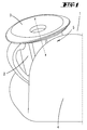
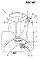
- a food processor 1 with a mixing vessel 2, a the mixing vessel 2 closing lid 3 and a, the mixing vessel 2 receiving housing. 4
- the housing 4 is an unillustrated electric motor for driving a likewise not shown, arranged in the mixing vessel 2 integrated agitator, which agitator motor via a turn, not shown Speed controller is controllable. Furthermore can in the housing 4 or bottom side of the mixing vessel 2, a heater may be provided, which has a corresponding Sachr is adjustable. Regarding the Arrangement and control of agitator and heating is For example, refer to EP-B1 0 757 530. The content This patent is hereby incorporated in full Also included in the disclosure of the present invention for the purpose, features of this patent in claims to include the present invention.
- a locking device. 5 provided, which with a cover portion 6 of the Cover 3 interacts.
- This lid portion 6 is in the illustrated embodiment as a radial over the lid edge protruding web formed.
- the arranged in hiding position in the housing 4 locking device 5 is through this lid section 6 beaufschlagbar by turning the Dekkels 3 or by turning the mixing vessel 2 with the lid 3 around the vessel axis x of the lid portion 6, a corresponding arranged, slot-like housing opening. 7 passing, into the area of action of the locking device 5 retracts.
- the locking device 5 is essentially together from one, with properly attached Cover 3 on the mixing vessel 2 in the plane of rotation of the Cover section 6 pivotable release element. 9 and one perpendicular to the displacement plane of the release element with this cooperating locking element 10 together.
- the release element 9 is essentially one aligned parallel to the agitator axis x, at the Housing wall molded pin 11 pivotally, wherein a radially projecting boom 12 for cooperation is formed with the lid portion 6.
- a spring extension 13th molded, for biasing the release element 9 in one, the locking element 10 blocking position as shown in Fig. 2.
- the spring extension 13th is supported on a housing section.
- the locking element 10 is in the form of, below a, the release element 9 bearing plate 14 tiltably mounted rocker formed and exists essentially two at a right angle arranged legs 15, 16, wherein the a leg 15 for cooperation with the release element 9 is formed and the other leg 16 in Area of its free end has journals, the in accordance formed, on the support plate 14th on the underside arranged Garböckchen 17 engage.
- the arrangement is chosen so that the tilt axis y of the locking element 10 extends transversely to Swivel axis z of the release element.
- the locking element 10 is underside by a Plunger 18 of an electromagnet 19 in the direction of the Release element 9 acted upon, including the Kippverlagerung of the locking element 10 one of the one Leg 15 of the locking element 10 passing Opening 20 is provided in the holding plate 14.
- the solenoid is also particularly in case of failure switched off directly.
- the cover portion 6 dives through the housing opening 7 in the region of the release element 9 and drags the boom 12 of the release element 9 with what a pivotal displacement of the release element 9 about its pivot axis z against the force of the spring extension 13 has the result.
- a path for the locking element 10 when exposed to the underside of the same by the electromagnet 19 is released.
- a window-like passage 23 is formed in the release element 9.
- the electromagnet 19 is then actuated when the device is switched on, the extending plunger 18 causes the tilting displacement of the locking element 10, whereby the free end of the leg 19, the opening 20 of the retaining plate 14, penetrates into the passage 23 of the release element 9.
- the underside of the electromagnet 19 the actuation of the switch 22 through the cam 21, for two-pole voltage application of a heating plant and / or the agitator motor.
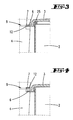
- the embodiment according to the invention also an improper placement of the Dekkels 3 detectable. Is one between the lid 3 and Stirring vessel 2 to be arranged cover seal 25 is not or not properly attached to the lid 3, so is the relative height of the lid 3 to the housing 4th reduced by the amount of the sealing height. Thereby are the radial section 8 and in particular the lid portion 6 in a position below the Release element 9.
- the housing opening 7 is corresponding dimensioned in vertical extent (see Fig. 3 and 4).
- the cover section 6 undoes the release element 9. The latter thus remains in its starting position.
- the locking element 10 can not in the intended passage 23 of the release element 9 dive, bringing the startup of the food processor 1 is prevented.
- the described locking device 5 in the Housing 4 can also with a corresponding shaped radial section of the mixing vessel. 2 interact, whereby the correct insertion of the Rhakgefäßes 2 can be detected.
- a combination of lid 3 to be detected and Rhakgefäß 2 by means of separately or together too detecting radial sections conceivable.
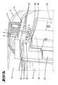
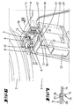
- FIGS. 10 to 18 show the invention with reference to FIG second embodiment. Again, this is in the Housing 4 a locking device 5 is provided which with one as a radial over the edge of the lid protruding web shaped lid section 6 interacts.
- a locking entrainment member 30 is provided. This forms in the locking plane E between the mixing vessel 2 and the lid 3 is an approximately dovetailed radially inwardly opening entrainment section 31 off, which one at, one parallel to the agitator axis x extending pivot axis z rotatable mounted driving base 32 is formed.
- At this driving base 32 is a radially projecting, in plan approximately semicircular curved running Mit fortunearm 33 molded, which in the area its free end a down-facing driving pin 34 owns.
- the driving arm 33 includes an end of an operating rod 35. In this end area is at axial distance to the free end one transverse to the local longitudinal axis the rod end portion projecting drive disc 36 formed, which latter an open-edge Radial recess 37 for entry of the driving pin 34th has.
- a Ball head 38 is formed, which is mounted in a not shown, housing-side pan.
- the actuating rod 35 extends essentially in axial extension to the head, covered by the driving arm 33 End, with which a line connecting these two ends at the same time a longitudinal axis a of the actuating rod 35th forms. Between these two end areas runs the actuating rod 35 is cranked several times.
- the foot carries the actuating rod 35 a projecting transversely to its local longitudinal axis a ' Blocking disk 39.
- the latter extends only over a part of the circumference of the actuating rod 35, so in the illustrated embodiment about about 100 to 120 °.
- the blocking disk 39 extends in its circumferential extent into an engagement tooth 40 via, which latter approximately tangential to the actuating rod 35 extending is arranged.
- the free tip of the mesh tooth 40 ends on an imaginary extension of the Blocking disc edge.
- Blocking disc 39 cooperates with a, with a speed controller 41 rotatably coupled locking element 10.
- the latter is one end, one Control board 42 passing through the speed controller axle body attached. A rotary control of the speed controller 41 is thus directly on the locking element 10 transmitted.
- the locking element 10 is approximately circular formed with a circumferential groove 43 and one, this Circumferential groove 43 crossing, in the direction of the axis of rotation b the speed controller 41 and the locking element 10 extending blocking groove 44th
- a leg spring 45 is provided which is supported on one side of the housing and with their other End of the actuating rod 35 and over this the locking driving part 30 in a lid release position according to Fig. 15 applied.
- FIGS. 10 to 13 illustrate the situation which occurs when the lid 3 is in the correct position.
- the locking driving member 30 is rotated with respect to Fig. 11 in the clockwise direction about the pivot axis z, after which the lid portion 6 is caught in the illustrated dovetail rotational position of the lid portion 6 in the dovetail opening driving portion 31 .
- the actuating rod 35 is rotated about the longitudinal axis a.
- the foot side formed on the actuating rod 35 blocking disk 39 assumes the position shown in FIGS. 12 and 13, wherein this blocking disk 39 is displaced out of engagement with the blocking groove 44 of the locking element 10.
- the engagement tooth 40 engages in this operating position in the circumferential groove 43 of the locking element 10, which has a rotational displacement of the locking element 10 via the speed controller 41 from the off position out a rotational blocking of the actuating rod 35 result. Since the engagement tooth 40 is caught in the twisted position of the locking element 10 in the direction of rotation of the actuating rod 35 in the circumferential groove 43, a return displacement of the locking entrainment member 30 to release the lid 3 is prevented. This ensures that the lid 3 can not be removed when the stirrer is switched on.
- an electrical Switch 46 is provided, which in properly attached Cover 3 via the actuating rod 35 and the it is actuated blocking disk 39 is actuated, so that the power supply of the control board 42 is released. It is preferred via the switch 46th the power supply of the agitator and if necessary a heater released. Since the filling of the mixing vessel 2 usually takes place with the cover removed 3, proves to be advantageous if any provided weighing device regardless of the position the locking device 5 and thus an admission of the switch 46 operates.
Landscapes
- Engineering & Computer Science (AREA)
- Food Science & Technology (AREA)
- Mechanical Engineering (AREA)
- Food-Manufacturing Devices (AREA)
- Mixers Of The Rotary Stirring Type (AREA)
- General Preparation And Processing Of Foods (AREA)
- Beans For Foods Or Fodder (AREA)
- Saccharide Compounds (AREA)
Abstract
Description
Das Freigabeelement ist hierbei Bestandteil des das Rührgefäß aufnehmenden Gehäuses. Eine Betätigung desselben erfolgt durch ein Verdrehen des Rührgefäßes und/oder des Deckels um die Gefäß-Vertikalachse, welche Drehbewegung weiter bevorzugt anschlagbegrenzt ist. Diese, die Betriebsstellung des Rührgefäßes und/oder des Deckels definierende Verdrehstellung ist durch das hiernach freigegebene, bevorzugt gehäuseseitige Verriegelungselement verriegelt, so dass ein Eingriff in das Rührgefäß während des Betriebs nicht möglich ist. Diesbezüglich wird weiter eine Drehbetätigung des Freigabeelementes durch Beaufschlagung mittels des Rührgefäβes und/oder des Deckels bevorzugt, wobei im Zuge dieser Freigabeelement-Drehbewegung der Weg für das-Verriegelungselement in Richtung auf eine Verriegelungsstellung freigegeben wird. Die Verlagerung des Verriegelungselementes in die Verriegelungsstellung erfolgt erst nach einem Einschalten der Küchenmaschine, insbesondere nach einem Einschalten des Rührwerkes, welche Verriegelungsstellung erst nach einem Ausschalten, weiter bevorzugt nach einem Stillstand des Rührwerkes aufgehoben wird. Des weiteren ist durch die erfindungsgemäße Ausgestaltung einer Inbetriebnahme der Küchenmaschine, insbesondere des Rührwerkes bei nicht vorhandenem Rührgefäß und/oder Deckel entgegengewirkt. Dies ist durch die Anordnung des Freigabeelementes erreicht, welches erst nach einer Verlagerung desselben, eben durch das Rührgefäß und/oder den Deckel den Weg zur Verlagerung des Verriegelungselementes freigibt. Der Versuch, die Küchenmaschine, insbesondere das Rührwerk, ohne Rührgefäß und/oder Deckel zu starten, wird durch Erfassen der nicht ermöglichten Verlagerung des Verriegelungselementes in die Verriegelungsstellung unterbunden. Diese Erfassung kann bspw. auf elektrischem bzw. elektronischem Wege erfolgen, so bspw. über einen durch das Verriegelungselement in der einen oder anderen Endstellung zu beaufschlagenden Schalter oder dergleichen. Bevorzugt wird weiter das Verriegelungselement und auch das Freigabeelement in einem geschützten Bereich innerhalb des Gehäuses angeordnet, wobei eine Gehäuseöffnung zur Beaufschlagung des Freigabeelementes durch das Rührgefäß und/oder den Deckel während des Betriebs durch das Rührgefäß und/oder den Deckel abgedeckt wird, so dass eventuell über den Gefäßrand bzw. den Deckelrand laufendes Gargut oder Ähnliches nicht in die betreffende Gehäuseöffnung eindringen kann, was zu einer Funktionsstörung der Verriegelungs- und Freigabemechanik führen würde. Um etwaigen Funktionsstörungen auf der, insbesondere die Funktion des Rührwerks steuernden Platine. in der Küchenmaschine entgegenzuwirken, wird vorgeschlagen, dass aufgrund der Verdrehung des Rührgefäßes und/oder des Deckels ein elektrischer Schalter betätigt wird, der die Stromversorgung einer Steuerungsplatine, jedenfalls im Hinblick auf bestimmte Funktionen der Steuerungsplatine freigibt. So ist erst bei Schalterbetätigung der, das Rührwerk beeinflussende Schaltkreis der Platine bestromt. Auch ein gegebenenfalls vorgesehener Schaltkreis einer Heizung kann entsprechend schalterbetätigbar aktiviert werden. Hingegen sind die Funktionen einer möglichen Wägeeinrichtung bevorzugt unabhängig von der Schalterstellung. Somit ist das Auswiegen im Rührgefäß auch ohne Verriegelung derselben bzw. ohne aufgesetzten Deckel möglich. Das Verriegelungselement kann insofern verriegelnd eingreifen, dass dieses bspw. in eine entsprechende Verriegelungsaufnahme des Rührgefäßes und/oder des Deckels eingreift. Bevorzugt wird jedoch eine Ausgestaltung, bei welcher das Verriegelungselement das Freigabeelement in der Freigabestellung verriegeln kann. Diese Freigabestellung entspricht der Stellung, in welcher das Rührwerk eingeschaltet werden kann. Darüber hinaus ist diesbezüglich vorgesehen, dass das verriegelte Freigabeelement das Rührgefäß und/oder den Deckel verriegelt. So kann bspw. ein der Verlagerung des Freigabeelementes dienender Abschnitt des Rührgefäßes und/oder des Deckels derart durch das Freigabeelement in der verschwenkten Position desselben gefangen sein, dass einem Zurückdrehen des Rührgefäßes und/oder des Deckels in die Ehtnahmestellung durch die Verriegelung des Freigabeelementes durch das Verriegelungselement verhindert ist. Der mit dem Freigabeelement zusammenwirkende Abschnitt kann hierbei weiter bspw. ein radial abragender Betätigungs-/Verriegelungs-Steg sein. Zur weiteren Erhöhung der Funktionssicherheit wird vorgeschlagen, dass das Freigabeelement in eine, eine Verlagerung des Verriegelungselementes sperrende Stellung vorgespannt ist, so dass durch die Vorspannung das Freigabeelement stets in eine Grundstellung beaufschlagt ist, in welcher der Verlagerungsweg für das Verriegelungselement versperrt ist. Es bedarf somit keiner manuellen Ausrückung des Freigabeelementes in die sperrende Stellung. Vielmehr wird diese stets selbsttätig erreicht. Die Verriegelung des Freigabeelementes ist bspw. dadurch realisiert, dass ein Abschnitt des Verriegelungselementes in eine entsprechend positionierte, fensterartige Öffnung des Freigabeelementes eintaucht. Diesbezüglich kann es sich als vorteilhaft erweisen, wenn diese Verriegelungsstellung nicht selbsthemmend ausgebildet ist. Vielmehr ist es hierbei von Vorteil, wenn diese Stellung durch den mit dem Freigabeelement zusammenwirkenden Abschnitt des Rührgefäßes und/oder des Deckels gehalten wird. Ohne diese Beaufschlagung des Freigabeelementes durch den Gefäß- bzw. Deckelabschnitt verlagert sich das Freigabeelement, bedingt durch die angesprochene Vorspannung, zurück in Richtung Grundstellung, was zugleich eine Rückverlagerung des Verriegelungselementes, deren mit dem Freigabeelement zusammenwirkender Abschnitt bspw. eine mit dem Freigabeelement-Ausnehmungsrand zusammenwirkende Auslenkschräge aufweist, bewirkt. Das Verriegelungselement kann des weiteren in Form eines um eine Achse schwenkbar gelagerten Hebels gebildet sein, wobei weiter bevorzugt wird, dass das Verriegelungselement magnetbetätigt ist. Vorgeschlagen wird weiter, dass der Magnet durch einen Drehzahlsteller des Gerätes zu aktivieren ist. Demnach wird bei einem Versuch der Aktivierung des Rührwerkes über den Drehzahlsteller der Magnet beaufschlagt, was über einen Magnetstößel die Schwenkverlagerung des Verriegelungselementes bewirkt. Sofern durch ordnungsgemäßen Einsatz und Verdrehen des Rührgefäßes und/oder des Deckels das Freigabeelement verlagert wurde, kann das Verriegelungselement mittels des Magneten in die Verriegelungsstellung verschwenken.
Ist dies nicht der Fall, so wird dieser Fehlversuch detektiert, was ein Abfallen des Magneten und eine Nichtinbetriebnahme des Rührwerkes zur Folge hat. Als besonders vorteilhaft erweist sich weiter, dass das durch den Magneten bewirkte Verriegelungselement im Zuge der Bewegung in die Verriegelungsstellung zugleich einen Schalter für die Spannungsbeaufschlagung eines Heizwerkes und/oder eines Rührwerk-Motors betätigt. Demnach erfolgt die Spannungsbeaufschlagung nur dann, wenn das Rührgefäß und/oder der Deckel ordnungsgemäß eingesetzt und zur Verlagerung des Freigabeelementes verdreht sind. Des weiteren können durch den Magneten auch zeitgleich zwei Schalter betätigt werden, wodurch eine zwei-polige Schaltung zur Ansteuerung des Heizwerkes und/oder des Rührwerk-Motors erreicht werden kann. In einer Weiterbildung des Erfindungsgegenstandes ist vorgesehen, dass das Verriegelungselement mit dem Drehzahlsteller gekoppelt ist. Zufolge dieser Ausgestaltung ist bevorzugt eine mechanische Blockade des Drehzahlstellers gegeben, sofern das Rührgefäß und/oder der Deckel nicht in die Freigabestellung verschwenkt ist. Diese mechanische Blockierung kann alternativ aber auch, wie bevorzugt, kombinativ zu einem, eine elektrische Betätigung bzw. Unterbrechung eines, die Stromversorgung insbesondere des Rührwerks gewährleistenden Schalters vorgesehen sein. Bevorzugt wird hierbei eine Ausgestaltung, bei welcher der Drehzahlsteller bzw. ein mit dem Drehzahlsteller drehfest gekuppeltes Stellerelement das Verriegelungselement ist. Ist das Rührgefäß und/oder der Deckel nicht in die Freigabestellung verlagert, so ist durch die erfindungsgemäße mechanische Blockade ein Stellen des Drehzahlstellers aus der Aus-Position heraus nicht möglich. Ist hingegen das Rührgefäß und/oder der Deckel ordnungsgemäß in die Freigabestellung verdreht, so ist der das Verriegelungselement ausbildende Drehzahlsteller freigegeben und somit betätigbar. Hingegen ist bei einer Stellung des Drehzahlstellers bzw. des Verriegelungselementes jenseits der Aus-Stellung das Zurückdrehen des Rührgefäßes und/oder des Deckels in eine Entnahmestellung unterbunden. So kann auch bei dieser mechanischen Ausgestaltung der Verriegelung bei laufendem Rührwerk bspw. nicht der Deckel des Rührgefäßes entfernt werden. Diesbezüglich erweist es sich weiter als vorteilhaft, dass das Freigabeelement eine Betätigungsstange aufweist, welche die Verbindung zwischen einer Verriegelungsebene zwischen dem Rührgefäß und dem Deckel und dem Drehzahlsteller schafft. Diese Betätigungsstange ist des Weiteren bevorzugt jeweils endseitig in dem Gehäuse der Küchenmaschine gelagert. Das von dem Rührgefäß bzw. von dem Deckel zu betätigende Freigabeelement besteht weiter bevorzugt aus der Betätigungsstange und einem hiervon gesonderten Sperr-Mitnahmeteil, welch letzteres im Zusammenwirkungsbereich mit dem Rührgefäß bzw. dem Deckel gehäuseinnenseitig der Küchenmaschine um eine parallel zur Rührgefäßachse verlaufenden Längsachse drehbar gehaltert ist. Dieses Sperr-Mitnahmeteil wirkt auf die Betätigungsstange ein derart, dass das drehgelagerte Sperr-Mitnahmeteil die Betätigungsstange um eine Längsachse verdreht, wobei die Längsachse nicht zwangsläufig die Körperachse der Betätigungsstange sein muss. Vielmehr entspricht diese Längsachse einer die beiden Endlagerpunkte der Betätigungsstange verbindenden Linie, wobei ein unterer, dem Drehhzahlsteller bzw. dem Verriegelungselement zugeordneter Lagerpunkt, bevorzugt durch eine kugelkopfartige Lagerung in dem Maschinengehäuse gebildet ist und der gegenüberliegende, obere Lagerpunkt der Betätigungsstange durch einen Formschluss zwischen Betätigungsstange und Sperr-Mitnahmeteil ausgeformt ist. Weiterhin ist vorgesehen, dass die Betätigungsstange fußseitig eine quer zu ihrer örtlichen Längsachse vorragende Blockierungsscheibe aufweist zum Eingriff in eine, in Richtung einer Drehachse des Drehzahlstellers verlaufenden Blockierungsnut. Bei nicht ordnungsgemäß aufgesetztem Rührgefäß bzw. Deckel und demnach in einer Grundposition verharrendem Sperr-Mitnahmeteil greift die Blockierungsscheibe der Betätigungsstange in die zugeordnete Blockierungsnut des Drehzahlstellers bzw. des Verriegelungselementes ein, zur Drehblockierung desselben. Diesbezüglich ist weiter vorgesehen, dass die Blockierungsscheibe nur über einen Teil des Umfangs der Betätigungsstange ausgebildet ist, so dass durch ein Verdrehen des Rührgefäßes bzw. des Deckels in die Freigabestellung die Blockierungsscheibe über die Betätigungsstange aus der Blockierungsnut des Drehzahlstellers heraus bewegt wird, zur Drehfreigabe des Stellers. Die Umfangslänge der Blockierungsscheibe ist entsprechend dem Drehwinkel der Betätigungsstange zwischen Verriegelungs- und Freigabeposition angepasst. Um in dieser Freigabestellung des Drehzahlstellers das Abnehmen insbesondere des Deckels des Rührgefäßes, was zunächst eine Rückverdrehung desselben verlangt, bei einer Stellung des Drehzahlstellers außerhalb der Aus-Stellung zu verhindern, ist weiter vorgesehen, dass die Blockierungsscheibe in ihrer Umfangserstreckung in einen Eingriffszahn übergeht, der mit einer zugeordneten Umfangsnut des Drehzahlstellers zusammenwirkt und bei gewählter Drehzahl ein Verdrehen der Betätigungsstange hindert. Als handhabungstechnisch vorteilhaft erweist sich zudem eine Weiterbildung, bei welcher bevorzugt fußseitig der Betätigungsstange eine Schenkel-Rückstellfeder vorgesehen ist, welche die Betätigungsstange und über diese das Sperr-Mitnahmeteil in eine Deckel- bzw. Rührgefäß-Freigabestellung beaufschlagt. Des Weiteren ist in einer bevorzugten Ausgestaltung vorgesehen, dass die Betätigungsstange abgekröpft verläuft. Zudem können das Sperr-Mitnahmeteil sowie die Betätigungsstange als auch das mit dem Drehzahlsteller gekoppelte Verriegelungselement als Kunststoffteile, insbesondere Kunststoff-Spritzteile ausgeformt sein. In einer bevorzugten Ausgestaltung des Erfindungsgegenstandes ist vorgesehen, dass das Freigabeelement durch einen Deckelabschnitt bewegbar ist. Demzufolge ist zur Inbetriebnahme der Maschine, insbesondere des Rührwerkes, ein ordnungsgemäß auf das Rührgefäß aufgesetzter und hiernach in eine Sicherungsstellung verdrehter Deckel Bedingung. Der mit dem Freigabeelement zusammenwirkende Deckelabschnitt kann hierbei als radial abkragender Steg ausgebildet sein. Hieraus ergibt sich der weitere Vorteil, dass unterhalb des Freigabeelementes ein solcher Freiraum gegeben ist, dass der Deckelabschnitt das Freigabeelement unterläuft, wenn sich der Deckelabschnitt nicht auf einem vorbestimmten Höhenniveau befindet. So kann durch die erfindungsgemäße Anordnung neben dem Vorhandensein des Deckels auch erfasst werden, ob eine Dichtung zwischen Deckel und Gefäß eingelegt ist. Ist dies nicht der Fall oder ist diese nicht ordnungsgemäß eingesetzt, so wird die relative Höhenlage des Deckels zu dem Gehäuse um den Betrag der Dichtungshöhe reduziert. Dadurch befindet sich der mit dem Freigabeelement zusammenwirkende Deckelabschnitt in einer Position unterhalb des Freigabeelementes. Bei dem Versuch, den Deckel durch Drehung zu arretieren, taucht der Deckelabschnitt zwischen dem Freigabeelement und dem Gehäuse hindurch, so dass das Freigabeelement in seiner Ausgangsposition verbleibt und demnach das Verriegelungselement nicht in die gewünschte mechanische Verriegelungsstellung bzw. elektrische Freigabestellung für das Heizwerk und/oder den Rührwerk-Motor verlagert werden kann.
- Fig. 1
- eine perspektivische Ausschnittdarstellung einer erfindungsgemäßen Küchenmaschine mit einem deckelverschlossenen und in das Gehäuse der Küchenmaschine eingesetzten Rührgefäß, eine erste Ausführungsform betreffend;
- Fig. 2
- eine partiell geschnittene perspektivische Ausschnittsdarstellung eines Zusammenwirkungsbereiches eines Deckelabschnittes und einer gehäuseseitigen Verriegelungseinrichtung, die entriegelte Stellung betreffend;
- Fig. 3
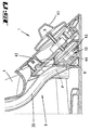
- den Schnitt gemäß der Linie III-III in Fig. 2 bei ordnungsgemäßer Anordnung von Rührgefäß, Deckel und zwischengeschalteter Dichtung;
- Fig. 4
- eine der Fig. 3 entsprechende Schnittdarstellung, jedoch eine nicht ordnungsgemäße Anordnung betreffend;
- Fig. 5
- eine weitere perspektivische, partiell geschnittene Detaildarstellung mit Blick auf ein magnetbetätigbares Verriegelungselement, gleichfalls die entriegelte Stellung betreffend;
- Fig. 6
- eine weitere perspektivische, partiell geschnittene Detaildarstellung des Zusammenwirkungsbereiches von Deckelabschnitt und Verriegelungsanordnung, die verriegelte Stellung betreffend;
- Fig. 7
- den Schnitt gemäß der Linie VII-VII in Fig. 6;
- Fig. 8
- eine weitere partiell geschnittene, perspektivische Darstellung des Zusammenwirkungsbereiches in der Verriegelungsstellung;
- Fig. 9
- eine perspektivische Darstellung, den Bereich zweier, in der Verriegelungsstellung betätigte Schalter betreffend;
- Fig. 10
- eine perspektivische Darstellung einer erfindungsgemäßen Küchenmaschine mit einem deckelverschlossenen und in das Gehäuse der Küchenmaschine eingesetztem Rührgefäß, eine zweite Ausführungsform betreffend;
- Fig. 11
- den Schnitt gemäß der Linie XI-XI in Fig. 10;
- Fig. 12
- eine vereinfachte perspektivische Darstellung eines Zusammenwirkungsbereiches zwischen einer Betätigungsstange und einem mit einem Drehzahlsteller drehgekoppelten Verriegelungselement;
- Fig. 13
- die Ansicht gemäß Pfeil XIII in Fig. 12;
- Fig. 14
- eine der Fig. 10 entsprechende Darstellung, jedoch bei nicht aufgesetztem Rührgefäßdeckel;
- Fig. 15
- den Schnitt gemäß der Linie XV-XV in Fig. 14;
- Fig. 16
- eine der Fig. 13 entsprechende Darstellung, jedoch in der den Drehzahlsteller verriegelnden Position der Betätigungsstange;
- Fig. 17
- den vergrößert dargestellten Schnitt gemäß der Linie XVII-XVII in Fig. 10;
- Fig. 18
- eine schematische Explosionsperspektive der der Verriegelung dienenden Elemente.
Bei Erreichen einer definierten Endstellung, in welcher der Ausleger 12 zwischen dem Radialabschnitt 8 und dem Deckelabschnitt 6 des Deckels 3 gefangen ist, ist ein Weg für das Verriegelungselement 10 bei unterseitiger Beaufschlagung desselben durch den Elektromagneten 19 freigegeben. Hierzu ist in dem Freigabeelement 9 ein fensterartiger Durchgang 23 ausgeformt. Wird hiernach bei einem Einschalten des Gerätes der Elektromagnet 19 betätigt, so bewirkt der ausfahrende Stößel 18 die Kippverlagerung des Verriegelungselementes 10, wobei das freie Ende des Schenkels 19, die Durchbrechung 20 der Halteplatte 14 durchtretend in den Durchgang 23 des Freigabeelementes 9 eintaucht. Gleichzeitig erfolgt unterseitig des Elektromagneten 19 die Betätigung der Schalter 22 durch den Nocken 21, zur zweipoligen Spannungsbeaufschlagung eines Heizwerkes und/oder des Rührwerk-Motors.
Somit ist sichergestellt, dass der Deckel 3 bei eingeschaltetem Rührwerk nicht entfernt werden kann.
Claims (19)
- Küchenmaschine (1) mit einem Rührgefäß (2), einem Deckel (3) und einem Gehäuse (4), wobei das Rührgefäß (2) und der Deckel (3) derart verriegelbar sind, dass ein Eingriff in das Rührgefäß (2) während des Betriebs nicht möglich ist, wobei weiter das Rührgefäß (2) und/oder der Deckel (3) durch Verdrehen um die Vertikalachse (x) des Rührgefäßes (2) ein Freigabeelement (9) verlagern, das nach erfolgter Verlagerung den Weg für ein Verriegelungselement (10) freigibt, dadurch gekennzeichnet, dass das Freigabeelement (9) gesondert von dem Rührgefäß (2) und/oder dem Deckel (3) ausgebildet ist und dass das Freigabeelement (9) durch Verdrehen des Rührgefäßes (2) und/oder des Deckels (3) um die Vertikalachse (x) des Rührgefäßes (2) betätigt wird und nach erfolgter Verdrehung den Weg für das Verriegelungselement (10) freigibt.
- Küchenmaschine nach Anspruch 1 oder insbesondere danach, dadurch gekennzeichnet, dass aufgrund der Verdrehung des Rührgefäßes (2) und/oder des Deckels (3) ein elektrischer Schalter (46) betätigt wird, der die Stromversorgung einer Steuerungsplatine (42), jedenfalls im Hinblick auf bestimmte Funktionen der Steuerungsplatine (42) freigibt.
- Küchenmaschine nach einem oder mehreren der vorhergehenden Ansprüche oder insbesondere danach, dadurch gekennzeichnet, dass das Verriegelungselement (10) das Freigabeelement (9) in der Freigabestellung verriegeln kann.
- Küchenmaschine nach einem oder mehreren der vorhergehenden Ansprüche oder insbesondere danach, dadurch gekennzeichnet, dass das verriegelte Freigabeelement (9) das Rührgefäß (2) und/oder den Deckel (3) verriegelt.
- Küchenmaschine nach einem oder mehreren der vorhergehenden Ansprüche oder insbesondere danach, dadurch gekennzeichnet, dass das Freigabeelement (9) in eine, einer Verlagerung des Verriegelungselementes (10) sperrende Stellung vorgespannt ist.
- Küchenmaschine nach einem oder mehreren der vorhergehenden Ansprüche oder insbesondere danach, dadurch gekennzeichnet, dass das Verriegelungselement (10) magnetbetätigt ist.
- Küchenmaschine nach einem oder mehreren der vorhergehenden Ansprüche oder insbesondere danach, dadurch gekennzeichnet, dass der Magnet (19) durch einen Drehzahlsteller des Gerätes zu aktivieren ist.
- Küchenmaschine nach einem oder mehreren der vorhergehenden Ansprüche oder insbesondere danach, dadurch gekennzeichnet, dass das durch den Magneten (19) bewirkte Verriegelungselement (10) im Zuge der Bewegung in die Verriegelungsstellung zugleich einen Schalter (22) für die Spannungsbeaufschlagung eines Heizwerkes und/oder eines Rührwerk-Motors betätigt.
- Küchenmaschine nach einem oder mehreren der vorhergehenden Ansprüche oder insbesondere danach, dadurch gekennzeichnet, dass das Verriegelungselement (10) mit dem Drehzahlsteller (41) gekoppelt ist.
- Küchenmaschine nach einem oder mehreren der vorhergehenden Ansprüche oder insbesondere danach, dadurch gekennzeichnet, dass der Drehzahlsteller (41) das Verriegelungselement (10) ist.
- Küchenmaschine nach einem oder mehreren der vorhergehenden Ansprüche oder insbesondere danach, dadurch gekennzeichnet, dass das Freigabeelement (9) eine Betätigungsstange (35) aufweist, welche die Verbindung zwischen einer Verriegelungsebene (E) zwischen dem Rührgefäß (2) und dem Deckel (3) und dem Drehzahlsteller (41) schafft.
- Küchenmaschine nach einem oder mehreren der vorhergehenden Ansprüche oder insbesondere danach, dadurch gekennzeichnet, dass das Freigabeelement (9) aus der Betätigungsstange (35) und einem hiervon gesonderten Sperr-Mitnahmeteil (30) besteht.
- Küchenmaschine nach einem oder mehreren der vorhergehenden Ansprüche oder insbesondere danach, dadurch gekennzeichnet, dass das drehgelagerte Sperr-Mitnahmeteil (30) die Betätigungsstange (35) um eine Längsachse (a) verdreht.
- Küchenmaschine nach einem oder mehreren der vorhergehenden Ansprüche oder insbesondere danach, dadurch gekennzeichnet, dass die Betätigungsstange (35) fußseitig eine quer zu ihrer örtlichen Längsachse (a') vorragende Blockierungsscheibe (39) aufweist zum Eingriff in eine, in Richtung einer Drehachse (b) des Drehzahlstellers (41) verlaufenden Blockierungsnut (44).
- Küchenmaschine nach einem oder mehreren der vorhergehenden Ansprüche oder insbesondere danach, dadurch gekennzeichnet, dass die Blockierungsscheibe (39) nur über einen Teil des Umfangs der Betätigungsstange (35) ausgebildet ist.
- Küchenmaschine nach einem oder mehreren der vorhergehenden Ansprüche oder insbesondere danach, dadurch gekennzeichnet, dass die Blockierungsscheibe (39) in ihrer Umfangserstreckung in einen Eingriffszahn (40) übergeht, der mit einer zugeordneten Umfangsnut (43) des Drehzahlstellers (41) zusammenwirkt und bei gewählter Drehzahl ein Verdrehen der Betätigungsstange (35) hindert.
- Küchenmaschine nach einem oder mehreren der vorhergehenden Ansprüche oder insbesondere danach, dadurch gekennzeichnet, dass die Betätigungsstange (35) abgekröpft verläuft.
- Küchenmaschine nach einem oder mehreren der vorhergehenden Ansprüche oder insbesondere danach, dadurch gekennzeichnet, dass das Freigabeelement (9) durch einen Deckelabschnitt (6) bewegbar ist.
- Küchenmaschine nach einem oder mehreren der vorhergehenden Ansprüche oder insbesondere danach, dadurch gekennzeichnet, dass unterhalb des Freigabeelementes (9) ein solcher Freiraum gegeben ist, dass der Deckelabschnitt (6) das Freigabeelement (9) unterläuft, wenn sich der Deckelabschnitt (6) nicht auf einem vorbestimmten Höhenniveau befindet.
Priority Applications (1)
| Application Number | Priority Date | Filing Date | Title |
|---|---|---|---|
| DE50212094.0A DE50212094C5 (de) | 2001-06-29 | 2002-06-27 | Küchenmaschine |
Applications Claiming Priority (4)
| Application Number | Priority Date | Filing Date | Title |
|---|---|---|---|
| DE10131483 | 2001-06-29 | ||
| DE10131483 | 2001-06-29 | ||
| DE10226941A DE10226941A1 (de) | 2001-06-29 | 2002-06-17 | Küchenmaschine |
| DE10226941 | 2002-06-17 |
Publications (2)
| Publication Number | Publication Date |
|---|---|
| EP1269898A1 true EP1269898A1 (de) | 2003-01-02 |
| EP1269898B1 EP1269898B1 (de) | 2008-04-16 |
Family
ID=26009611
Family Applications (1)
| Application Number | Title | Priority Date | Filing Date |
|---|---|---|---|
| EP02014300A Expired - Lifetime EP1269898B1 (de) | 2001-06-29 | 2002-06-27 | Küchenmaschine |
Country Status (4)
| Country | Link |
|---|---|
| EP (1) | EP1269898B1 (de) |
| AT (1) | ATE392170T1 (de) |
| DE (2) | DE50212094D1 (de) |
| ES (1) | ES2301589T3 (de) |
Cited By (8)
| Publication number | Priority date | Publication date | Assignee | Title |
|---|---|---|---|---|
| WO2005094649A1 (de) * | 2004-03-31 | 2005-10-13 | BSH Bosch und Siemens Hausgeräte GmbH | Haushaltsgerät mit zentralbetätigung |
| EP2371251A1 (de) | 2010-03-31 | 2011-10-05 | Vorwerk & Co. Interholding GmbH | Elektromotorisch betriebene Küchenmaschine, sowie Zubereitungsgefäß |
| DE102010016248A1 (de) | 2010-03-31 | 2011-10-06 | Vorwerk & Co. Interholding Gmbh | Elektromotorisch betriebene Küchenmaschine, sowie Zubereitungsgefäß |
| DE102010016250A1 (de) | 2010-03-31 | 2011-10-06 | Vorwerk & Co. Interholding Gmbh | Elektromotorisch betriebene Küchenmaschine, sowie Zubereitungsgefäß |
| DE102010037102A1 (de) | 2010-08-23 | 2012-02-23 | Vorwerk & Co. Interholding Gmbh | Elektromotorisch betriebene Küchenmaschine, sowie Zubereitungsgefäß |
| DE102012217516A1 (de) | 2011-09-28 | 2013-03-28 | Hameur S.A. | Apparat zum Verarbeiten von Lebensmitteln mit gesichertem Deckel |
| DE102017121946A1 (de) | 2017-09-21 | 2019-03-21 | Vorwerk & Co. Interholding Gmbh | Elektromotorisch betriebene Küchenmaschine |
| DE102017123689A1 (de) | 2017-10-11 | 2019-04-11 | Vorwerk & Co. Interholding Gmbh | Elektromotorisch betriebene Küchenmaschine |
Families Citing this family (1)
| Publication number | Priority date | Publication date | Assignee | Title |
|---|---|---|---|---|
| PT2805653T (pt) | 2013-05-24 | 2020-10-06 | Taurus Res And Development Slu | Aparelho de cozinha para o processamento e preparação de alimentos |
Citations (6)
| Publication number | Priority date | Publication date | Assignee | Title |
|---|---|---|---|---|
| US4373677A (en) * | 1979-11-24 | 1983-02-15 | Matsushita Electric Industrial Co., Ltd. | Safety device for electric motor driven kitchen utensils |
| EP0081874A1 (de) * | 1981-12-11 | 1983-06-22 | Braun Aktiengesellschaft | Haushaltsgerät |
| EP0270851A1 (de) * | 1986-11-24 | 1988-06-15 | Braun Aktiengesellschaft | Anordnung zur Positionierung und lösbaren Befestigung eines Arbeitsbehälters |
| DE4309033A1 (de) * | 1993-03-20 | 1994-09-22 | Braun Ag | Sicherheitsschaltvorrichtung für elektrische Geräte |
| EP0638273A1 (de) * | 1993-08-04 | 1995-02-15 | Koninklijke Philips Electronics N.V. | Küchengerät mit einer Deckelverriegelungsvorrichtung mit Zentrifugalelement |
| US5979806A (en) * | 1996-11-11 | 1999-11-09 | Braun Gmbh | Food processor |
-
2002
- 2002-06-27 DE DE50212094T patent/DE50212094D1/de not_active Expired - Lifetime
- 2002-06-27 ES ES02014300T patent/ES2301589T3/es not_active Expired - Lifetime
- 2002-06-27 AT AT02014300T patent/ATE392170T1/de not_active IP Right Cessation
- 2002-06-27 DE DE50212094.0A patent/DE50212094C5/de not_active Expired - Lifetime
- 2002-06-27 EP EP02014300A patent/EP1269898B1/de not_active Expired - Lifetime
Patent Citations (6)
| Publication number | Priority date | Publication date | Assignee | Title |
|---|---|---|---|---|
| US4373677A (en) * | 1979-11-24 | 1983-02-15 | Matsushita Electric Industrial Co., Ltd. | Safety device for electric motor driven kitchen utensils |
| EP0081874A1 (de) * | 1981-12-11 | 1983-06-22 | Braun Aktiengesellschaft | Haushaltsgerät |
| EP0270851A1 (de) * | 1986-11-24 | 1988-06-15 | Braun Aktiengesellschaft | Anordnung zur Positionierung und lösbaren Befestigung eines Arbeitsbehälters |
| DE4309033A1 (de) * | 1993-03-20 | 1994-09-22 | Braun Ag | Sicherheitsschaltvorrichtung für elektrische Geräte |
| EP0638273A1 (de) * | 1993-08-04 | 1995-02-15 | Koninklijke Philips Electronics N.V. | Küchengerät mit einer Deckelverriegelungsvorrichtung mit Zentrifugalelement |
| US5979806A (en) * | 1996-11-11 | 1999-11-09 | Braun Gmbh | Food processor |
Cited By (12)
| Publication number | Priority date | Publication date | Assignee | Title |
|---|---|---|---|---|
| WO2005094649A1 (de) * | 2004-03-31 | 2005-10-13 | BSH Bosch und Siemens Hausgeräte GmbH | Haushaltsgerät mit zentralbetätigung |
| EP2371251A1 (de) | 2010-03-31 | 2011-10-05 | Vorwerk & Co. Interholding GmbH | Elektromotorisch betriebene Küchenmaschine, sowie Zubereitungsgefäß |
| CN102204793A (zh) * | 2010-03-31 | 2011-10-05 | 德国福维克控股公司 | 电机驱动的厨房设备以及烹饪容器 |
| DE102011000219A1 (de) | 2010-03-31 | 2011-10-06 | Vorwerk & Co. Interholding Gmbh | Elektromotorisch betriebene Küchenmaschine, sowie Zubereitungsgefäß |
| DE102010016248A1 (de) | 2010-03-31 | 2011-10-06 | Vorwerk & Co. Interholding Gmbh | Elektromotorisch betriebene Küchenmaschine, sowie Zubereitungsgefäß |
| DE102010016250A1 (de) | 2010-03-31 | 2011-10-06 | Vorwerk & Co. Interholding Gmbh | Elektromotorisch betriebene Küchenmaschine, sowie Zubereitungsgefäß |
| DE102010037102A1 (de) | 2010-08-23 | 2012-02-23 | Vorwerk & Co. Interholding Gmbh | Elektromotorisch betriebene Küchenmaschine, sowie Zubereitungsgefäß |
| DE102012217516A1 (de) | 2011-09-28 | 2013-03-28 | Hameur S.A. | Apparat zum Verarbeiten von Lebensmitteln mit gesichertem Deckel |
| US9101248B2 (en) | 2011-09-28 | 2015-08-11 | Hameur S.A. | Food processor with a protected lid |
| DE102012217516B4 (de) | 2011-09-28 | 2019-08-14 | Hameur S.A. | Apparat zum Verarbeiten von Lebensmitteln mit gesichertem Deckel |
| DE102017121946A1 (de) | 2017-09-21 | 2019-03-21 | Vorwerk & Co. Interholding Gmbh | Elektromotorisch betriebene Küchenmaschine |
| DE102017123689A1 (de) | 2017-10-11 | 2019-04-11 | Vorwerk & Co. Interholding Gmbh | Elektromotorisch betriebene Küchenmaschine |
Also Published As
| Publication number | Publication date |
|---|---|
| EP1269898B1 (de) | 2008-04-16 |
| ATE392170T1 (de) | 2008-05-15 |
| ES2301589T3 (es) | 2008-07-01 |
| DE50212094D1 (de) | 2008-05-29 |
| DE50212094C5 (de) | 2022-11-03 |
Similar Documents
| Publication | Publication Date | Title |
|---|---|---|
| EP1113745B1 (de) | Elektrisch beheizbarer wasserkocher | |
| DE60216044T2 (de) | Installationsanordnung zur steuerung der griffbetätigung bei einem türschloss und ein mit einer installationsanordnung dieser art versehenes türschloss | |
| DE69518108T2 (de) | Horizontalachsige Waschmaschine in Topladerbauweise | |
| DE69720597T2 (de) | Elektrisch betätigtes Autotürschloss | |
| DE69707300T2 (de) | Haushaltsgerät mit rotierendem messer zur zubereitung von lebensmitteln versehen mit sicherheitsvorrichtung | |
| WO2009150225A2 (de) | Schloss mit blockadehebel nebst austariertem schwerpunkt | |
| EP1269898B1 (de) | Küchenmaschine | |
| DE4322214C2 (de) | Abschließbarer Drehantrieb für Leistungsschalter | |
| DE10226941A1 (de) | Küchenmaschine | |
| DE102007060915B4 (de) | Schließvorrichtung mit Endlagensicherung | |
| DE69332114T2 (de) | Waschmittelbehälter für flüssige und/oder puderförmige Waschmittel, insbesondere für Waschmaschinen | |
| DE9403069U1 (de) | Nähfuß | |
| EP3812541A1 (de) | Kraftfahrzeug-schloss, insbesondere fahrzeug-heckklappe | |
| DE2556520C2 (de) | Verriegelungsvorrichtung | |
| DE60107321T2 (de) | Kraftfahrzeugschloss mit Kindersicherung und Diebstahlsicherung | |
| DE102007025295A1 (de) | Verschluß für ein Hausgerät | |
| DE10312093B4 (de) | Drehfallenschloss | |
| DE10312305B4 (de) | Türverriegelung für elektrische Geräte, insbesondere für Waschmaschinen | |
| DE4439374C1 (de) | Abschließbare Handbetätigungsvorrichtung zum Ein- und Ausschalten von gekapselten elektrischen Schaltgeräten, insbesondere von Leistungsschaltern | |
| DE10319952A1 (de) | Drehfallenschloss, bspw. Kofferraumschloss für ein Kraftfahrzeug | |
| WO1997031382A1 (de) | Schutzschalter mit verriegelungsvorrichtung gegen einschalten | |
| EP0823503B1 (de) | Mantelbeschickbare Trommelwaschmaschine | |
| EP1615532B1 (de) | Wasserkocher mit deckelverriegelung | |
| DE102024121702B3 (de) | Verschlussvorrichtung für eine Tür eines elektrischen Haushaltsgerätes | |
| AT394241B (de) | Schloss |
Legal Events
| Date | Code | Title | Description |
|---|---|---|---|
| PUAI | Public reference made under article 153(3) epc to a published international application that has entered the european phase |
Free format text: ORIGINAL CODE: 0009012 |
|
| AK | Designated contracting states |
Kind code of ref document: A1 Designated state(s): AT BE CH CY DE DK ES FI FR GB GR IE IT LI LU MC NL PT SE TR |
|
| AX | Request for extension of the european patent |
Free format text: AL;LT;LV;MK;RO;SI |
|
| 17P | Request for examination filed |
Effective date: 20030625 |
|
| AKX | Designation fees paid |
Designated state(s): AT BE CH CY DE DK ES FI FR GB GR IE IT LI LU MC NL PT SE TR |
|
| GRAP | Despatch of communication of intention to grant a patent |
Free format text: ORIGINAL CODE: EPIDOSNIGR1 |
|
| GRAS | Grant fee paid |
Free format text: ORIGINAL CODE: EPIDOSNIGR3 |
|
| GRAA | (expected) grant |
Free format text: ORIGINAL CODE: 0009210 |
|
| AK | Designated contracting states |
Kind code of ref document: B1 Designated state(s): AT BE CH CY DE DK ES FI FR GB GR IE IT LI LU MC NL PT SE TR |
|
| REG | Reference to a national code |
Ref country code: CH Ref legal event code: EP |
|
| REG | Reference to a national code |
Ref country code: IE Ref legal event code: FG4D Free format text: LANGUAGE OF EP DOCUMENT: GERMAN Ref country code: PT Ref legal event code: SC4A Free format text: AVAILABILITY OF NATIONAL TRANSLATION Effective date: 20080515 |
|
| REF | Corresponds to: |
Ref document number: 50212094 Country of ref document: DE Date of ref document: 20080529 Kind code of ref document: P |
|
| REG | Reference to a national code |
Ref country code: ES Ref legal event code: FG2A Ref document number: 2301589 Country of ref document: ES Kind code of ref document: T3 |
|
| NLV1 | Nl: lapsed or annulled due to failure to fulfill the requirements of art. 29p and 29m of the patents act | ||
| PG25 | Lapsed in a contracting state [announced via postgrant information from national office to epo] |
Ref country code: NL Free format text: LAPSE BECAUSE OF FAILURE TO SUBMIT A TRANSLATION OF THE DESCRIPTION OR TO PAY THE FEE WITHIN THE PRESCRIBED TIME-LIMIT Effective date: 20080416 Ref country code: FI Free format text: LAPSE BECAUSE OF FAILURE TO SUBMIT A TRANSLATION OF THE DESCRIPTION OR TO PAY THE FEE WITHIN THE PRESCRIBED TIME-LIMIT Effective date: 20080416 |
|
| REG | Reference to a national code |
Ref country code: IE Ref legal event code: FD4D |
|
| BERE | Be: lapsed |
Owner name: VORWERK & CO. INTERHOLDING G.M.B.H. Effective date: 20080630 |
|
| ET | Fr: translation filed | ||
| PG25 | Lapsed in a contracting state [announced via postgrant information from national office to epo] |
Ref country code: DK Free format text: LAPSE BECAUSE OF FAILURE TO SUBMIT A TRANSLATION OF THE DESCRIPTION OR TO PAY THE FEE WITHIN THE PRESCRIBED TIME-LIMIT Effective date: 20080416 Ref country code: IE Free format text: LAPSE BECAUSE OF FAILURE TO SUBMIT A TRANSLATION OF THE DESCRIPTION OR TO PAY THE FEE WITHIN THE PRESCRIBED TIME-LIMIT Effective date: 20080416 Ref country code: MC Free format text: LAPSE BECAUSE OF NON-PAYMENT OF DUE FEES Effective date: 20080630 Ref country code: SE Free format text: LAPSE BECAUSE OF FAILURE TO SUBMIT A TRANSLATION OF THE DESCRIPTION OR TO PAY THE FEE WITHIN THE PRESCRIBED TIME-LIMIT Effective date: 20080716 |
|
| REG | Reference to a national code |
Ref country code: CH Ref legal event code: PL |
|
| PLBE | No opposition filed within time limit |
Free format text: ORIGINAL CODE: 0009261 |
|
| STAA | Information on the status of an ep patent application or granted ep patent |
Free format text: STATUS: NO OPPOSITION FILED WITHIN TIME LIMIT |
|
| 26N | No opposition filed |
Effective date: 20090119 |
|
| GBPC | Gb: european patent ceased through non-payment of renewal fee |
Effective date: 20080716 |
|
| PG25 | Lapsed in a contracting state [announced via postgrant information from national office to epo] |
Ref country code: BE Free format text: LAPSE BECAUSE OF NON-PAYMENT OF DUE FEES Effective date: 20080630 |
|
| PG25 | Lapsed in a contracting state [announced via postgrant information from national office to epo] |
Ref country code: LI Free format text: LAPSE BECAUSE OF NON-PAYMENT OF DUE FEES Effective date: 20080630 Ref country code: CH Free format text: LAPSE BECAUSE OF NON-PAYMENT OF DUE FEES Effective date: 20080630 Ref country code: GB Free format text: LAPSE BECAUSE OF NON-PAYMENT OF DUE FEES Effective date: 20080716 |
|
| PG25 | Lapsed in a contracting state [announced via postgrant information from national office to epo] |
Ref country code: AT Free format text: LAPSE BECAUSE OF NON-PAYMENT OF DUE FEES Effective date: 20080627 |
|
| PG25 | Lapsed in a contracting state [announced via postgrant information from national office to epo] |
Ref country code: CY Free format text: LAPSE BECAUSE OF FAILURE TO SUBMIT A TRANSLATION OF THE DESCRIPTION OR TO PAY THE FEE WITHIN THE PRESCRIBED TIME-LIMIT Effective date: 20080416 |
|
| PG25 | Lapsed in a contracting state [announced via postgrant information from national office to epo] |
Ref country code: LU Free format text: LAPSE BECAUSE OF NON-PAYMENT OF DUE FEES Effective date: 20080627 |
|
| PG25 | Lapsed in a contracting state [announced via postgrant information from national office to epo] |
Ref country code: TR Free format text: LAPSE BECAUSE OF FAILURE TO SUBMIT A TRANSLATION OF THE DESCRIPTION OR TO PAY THE FEE WITHIN THE PRESCRIBED TIME-LIMIT Effective date: 20080416 |
|
| PG25 | Lapsed in a contracting state [announced via postgrant information from national office to epo] |
Ref country code: GR Free format text: LAPSE BECAUSE OF FAILURE TO SUBMIT A TRANSLATION OF THE DESCRIPTION OR TO PAY THE FEE WITHIN THE PRESCRIBED TIME-LIMIT Effective date: 20080717 |
|
| PG25 | Lapsed in a contracting state [announced via postgrant information from national office to epo] |
Ref country code: IT Free format text: LAPSE BECAUSE OF NON-PAYMENT OF DUE FEES Effective date: 20130627 |
|
| REG | Reference to a national code |
Ref country code: FR Ref legal event code: PLFP Year of fee payment: 15 |
|
| REG | Reference to a national code |
Ref country code: FR Ref legal event code: PLFP Year of fee payment: 16 |
|
| REG | Reference to a national code |
Ref country code: FR Ref legal event code: PLFP Year of fee payment: 17 |
|
| REG | Reference to a national code |
Ref country code: DE Ref legal event code: R008 Ref document number: 50212094 Country of ref document: DE Ref country code: DE Ref legal event code: R039 Ref document number: 50212094 Country of ref document: DE |
|
| PG25 | Lapsed in a contracting state [announced via postgrant information from national office to epo] |
Ref country code: IT Free format text: LAPSE BECAUSE OF NON-PAYMENT OF DUE FEES Effective date: 20130627 |
|
| PGRI | Patent reinstated in contracting state [announced from national office to epo] |
Ref country code: IT Effective date: 20200108 |
|
| PGFP | Annual fee paid to national office [announced via postgrant information from national office to epo] |
Ref country code: FR Payment date: 20210622 Year of fee payment: 20 Ref country code: DE Payment date: 20210621 Year of fee payment: 20 Ref country code: IT Payment date: 20210630 Year of fee payment: 20 Ref country code: PT Payment date: 20210618 Year of fee payment: 20 |
|
| PGFP | Annual fee paid to national office [announced via postgrant information from national office to epo] |
Ref country code: ES Payment date: 20210722 Year of fee payment: 20 |
|
| REG | Reference to a national code |
Ref country code: DE Ref legal event code: R071 Ref document number: 50212094 Country of ref document: DE |
|
| REG | Reference to a national code |
Ref country code: ES Ref legal event code: FD2A Effective date: 20220704 |
|
| REG | Reference to a national code |
Ref country code: DE Ref legal event code: R043 Ref document number: 50212094 Country of ref document: DE |
|
| PG25 | Lapsed in a contracting state [announced via postgrant information from national office to epo] |
Ref country code: ES Free format text: LAPSE BECAUSE OF EXPIRATION OF PROTECTION Effective date: 20220628 |
|
| PG25 | Lapsed in a contracting state [announced via postgrant information from national office to epo] |
Ref country code: PT Free format text: LAPSE BECAUSE OF EXPIRATION OF PROTECTION Effective date: 20220707 |
|
| REG | Reference to a national code |
Ref country code: DE Ref legal event code: R206 Ref document number: 50212094 Country of ref document: DE |