EP1267178B1 - Procédé de traitement d'une image à haute définition - Google Patents
Procédé de traitement d'une image à haute définition Download PDFInfo
- Publication number
- EP1267178B1 EP1267178B1 EP02013172A EP02013172A EP1267178B1 EP 1267178 B1 EP1267178 B1 EP 1267178B1 EP 02013172 A EP02013172 A EP 02013172A EP 02013172 A EP02013172 A EP 02013172A EP 1267178 B1 EP1267178 B1 EP 1267178B1
- Authority
- EP
- European Patent Office
- Prior art keywords
- raw data
- data elements
- accordance
- segment
- sensor
- Prior art date
- Legal status (The legal status is an assumption and is not a legal conclusion. Google has not performed a legal analysis and makes no representation as to the accuracy of the status listed.)
- Expired - Lifetime
Links
Images


Classifications
-
- G—PHYSICS
- G01—MEASURING; TESTING
- G01S—RADIO DIRECTION-FINDING; RADIO NAVIGATION; DETERMINING DISTANCE OR VELOCITY BY USE OF RADIO WAVES; LOCATING OR PRESENCE-DETECTING BY USE OF THE REFLECTION OR RERADIATION OF RADIO WAVES; ANALOGOUS ARRANGEMENTS USING OTHER WAVES
- G01S17/00—Systems using the reflection or reradiation of electromagnetic waves other than radio waves, e.g. lidar systems
- G01S17/88—Lidar systems specially adapted for specific applications
- G01S17/89—Lidar systems specially adapted for specific applications for mapping or imaging
-
- G—PHYSICS
- G01—MEASURING; TESTING
- G01S—RADIO DIRECTION-FINDING; RADIO NAVIGATION; DETERMINING DISTANCE OR VELOCITY BY USE OF RADIO WAVES; LOCATING OR PRESENCE-DETECTING BY USE OF THE REFLECTION OR RERADIATION OF RADIO WAVES; ANALOGOUS ARRANGEMENTS USING OTHER WAVES
- G01S17/00—Systems using the reflection or reradiation of electromagnetic waves other than radio waves, e.g. lidar systems
- G01S17/86—Combinations of lidar systems with systems other than lidar, radar or sonar, e.g. with direction finders
-
- G—PHYSICS
- G01—MEASURING; TESTING
- G01S—RADIO DIRECTION-FINDING; RADIO NAVIGATION; DETERMINING DISTANCE OR VELOCITY BY USE OF RADIO WAVES; LOCATING OR PRESENCE-DETECTING BY USE OF THE REFLECTION OR RERADIATION OF RADIO WAVES; ANALOGOUS ARRANGEMENTS USING OTHER WAVES
- G01S17/00—Systems using the reflection or reradiation of electromagnetic waves other than radio waves, e.g. lidar systems
- G01S17/88—Lidar systems specially adapted for specific applications
- G01S17/93—Lidar systems specially adapted for specific applications for anti-collision purposes
- G01S17/931—Lidar systems specially adapted for specific applications for anti-collision purposes of land vehicles
-
- G—PHYSICS
- G01—MEASURING; TESTING
- G01S—RADIO DIRECTION-FINDING; RADIO NAVIGATION; DETERMINING DISTANCE OR VELOCITY BY USE OF RADIO WAVES; LOCATING OR PRESENCE-DETECTING BY USE OF THE REFLECTION OR RERADIATION OF RADIO WAVES; ANALOGOUS ARRANGEMENTS USING OTHER WAVES
- G01S15/00—Systems using the reflection or reradiation of acoustic waves, e.g. sonar systems
- G01S15/88—Sonar systems specially adapted for specific applications
- G01S15/93—Sonar systems specially adapted for specific applications for anti-collision purposes
- G01S15/931—Sonar systems specially adapted for specific applications for anti-collision purposes of land vehicles
- G01S2015/932—Sonar systems specially adapted for specific applications for anti-collision purposes of land vehicles for parking operations
- G01S2015/933—Sonar systems specially adapted for specific applications for anti-collision purposes of land vehicles for parking operations for measuring the dimensions of the parking space when driving past
- G01S2015/935—Sonar systems specially adapted for specific applications for anti-collision purposes of land vehicles for parking operations for measuring the dimensions of the parking space when driving past for measuring the contour, e.g. a trajectory of measurement points, representing the boundary of the parking space
-
- G—PHYSICS
- G01—MEASURING; TESTING
- G01S—RADIO DIRECTION-FINDING; RADIO NAVIGATION; DETERMINING DISTANCE OR VELOCITY BY USE OF RADIO WAVES; LOCATING OR PRESENCE-DETECTING BY USE OF THE REFLECTION OR RERADIATION OF RADIO WAVES; ANALOGOUS ARRANGEMENTS USING OTHER WAVES
- G01S7/00—Details of systems according to groups G01S13/00, G01S15/00, G01S17/00
- G01S7/48—Details of systems according to groups G01S13/00, G01S15/00, G01S17/00 of systems according to group G01S17/00
- G01S7/4802—Details of systems according to groups G01S13/00, G01S15/00, G01S17/00 of systems according to group G01S17/00 using analysis of echo signal for target characterisation; Target signature; Target cross-section
Definitions
- the present invention relates to a method for processing a preferably depth-resolved image of a surveillance area, which was detected by an electromagnetic radiation sensor, in particular a laser scanner, during a scan of its field of view and comprises raw data elements that correspond to points on objects in the surveillance area and the coordinates of Positions and / or speeds and / or reflectivities of the object points included.
- an electromagnetic radiation sensor in particular a laser scanner
- Methods of the above type are known in principle.
- the generic method may be in particular methods for object recognition and tracking, with the objects in the field of view of the sensor, which may be, for example, an ultrasonic or radar sensor or an optoelectronic sensor, to be detected and tracked.
- objects are generated from the raw data elements that are to correspond to the detected objects. It is therefore necessary to assign pixels or raw data elements corresponding to object points of an object to an object that corresponds to the object. However, in the case of objects located close to each other, it may prove difficult to assign the pixels or raw data elements to the objects.
- the sensors may be, for example, ultrasonic or radar sensors. However, preference is given to optoelectronic sensors.
- a depth-resolved image of a sensor is understood to mean a set of pixels detected during a scanning of the field of view of the sensor, to which points or, depending on the resolution of the sensor, also correspond to regions of an object detected by the sensor, the pixels corresponding to the position of the associated object points Coordinates are assigned in at least two dimensions, which do not extend both perpendicular to the viewing direction of the sensor. Therefore, depth-resolved images also directly contain information about the distance of the object points corresponding to the pixels from the sensor. Alternatively or additionally, the pixels may also be assigned data about optical properties of the object points, for example reflectivities and / or colors.
- Sensors for electromagnetic radiation for detecting such depth-resolved images are basically known. These may preferably be optoelectronic sensors which offer good spatial resolution and are therefore preferred for the method according to the invention are. For example, systems with stereo video cameras can be used which have means for converting the raw data captured by the cameras into depth-resolved images.
- laser scanners which scan a viewing area with at least one pulsed radiation beam which sweeps over a predetermined angular range and detects from a point or area of an object, usually diffuse, reflected radiation pulses of the radiation beam.
- the transit time of the emitted, reflected and detected radiation pulses is detected for distance measurement.
- the raw data thus acquired for a pixel may then contain as coordinates the angle at which the reflex was detected and the distance of the object point determined from the transit time of the radiation pulses.
- the radiation may in particular be visible or infrared light.
- the visual range is understood to be the range actually scanned by the sensor, which may be smaller than the maximum scannable range.
- relationships are determined between the raw data elements of the image and the raw data elements are combined on the basis of the relationships according to at least one predetermined criterion to one or more segments, the relationships and / or the criterion depending on at least one segmentation parameter.
- the raw data elements comprise the position of an object point and its reflectivity
- the relationships between raw data elements comprise differences in the reflectivities of two object points each.
- Such a relationship between the raw data elements may additionally be distances of the positions of the raw data elements represent the positions of the object points corresponding to the raw data elements, or are deviations of other properties of the object points from each other whose values are contained in the raw data elements.
- optical properties of an object point are to be considered here.
- the property of an object point may, for example, also include a relative speed to a radar sensor, wherein differences of relative speeds to a radar sensor are then used as the segmentation criterion.
- the raw data elements can then be combined into one or more segments.
- a segment may also comprise only one raw data element.
- the relationships and / or the criterion depend on at least one segmentation parameter, which may be, for example, a value for the difference still permissible for a segment membership in a comparison of properties.
- the criterion may be, in particular, that the raw data elements have a maximum deviation from one another with respect to the specific property. This may in particular be the position, the relative speed to the sensor or, as mentioned above, optical properties.
- This segmental summary will produce a first reduction in the amount of data achieved, which facilitates further processing, since for many applications, only a treatment of the entire segments is relevant. Particularly in connection with object recognition and tracing methods, it can be more easily checked whether the segments found correspond individually or in groups to specific objects.
- the relationships between raw data elements comprise spatial element-element distances of the positions of each two raw data elements and a segment membership of a raw data element is determined only if at least the element-element distance of the position of the raw data element from the position of at least one other, the Segment attributable raw data element the value of a corresponding Segment michsparameters, which is also referred to as a separation parameter, falls short.
- the distance criterion used in this development generally forms only a necessary condition for a segment membership, which is only sufficient if no other relationship is used to determine a segment affiliation.
- This spatial relationship between raw data elements takes into account that objects for most applications are defined by their spatial relationship. Particularly in the context of a method for object recognition and tracking, the element-element distance represents a very meaningful relationship between the raw data elements.
- a nonnegative function of the coordinates of the positions of the two raw data elements may be used as the element-element distance of the positions of two raw data elements whose values are basically positive and which assumes the value zero only if the positions, that is, the coordinates, are identical are.
- Particularly preferred for determining the element-element distance of two raw data elements is a distance function of the differences of coordinates of the raw data elements and as a further segmentation parameter a weighting parameter is used, wherein the differences in different coordinate directions are weighted relative to each other via the weighting parameter.
- This may in particular be a Euclidean distance, in which the squared differences in different coordinate directions are weighted by a weighting parameter against each other, whereby anisotropy in the evaluation of the distances is achieved.
- this weighting means that raw data elements whose positions are far apart in a low weighted direction compared to the other direction may still belong to one segment.
- the relationships between raw data elements may include two element-element distances of the positions, each relating to one of the coordinates of the raw data elements and to each of which a further segmentation parameter is assigned, which is also referred to as a separation parameter.
- a segment membership of a raw data element is only determined if both element-element distances between the positions of the raw data element and the position of at least one other, the segment to be assigned Raw data item is below the values of the corresponding segmentation parameters.
- the relationships or associated criteria are only a necessary condition for segment membership, which is sufficient only if no other relationships are used.
- This segment membership condition which also relies on the spatial relationship of objects, can provide sharper results, in particular for segments that originate from angular objects.
- the separation parameters for the different coordinates can be chosen differently, so that the distances in different spatial directions can be assessed to different degrees.
- the element-element distances may, in particular, be the amount of the differences of the respective coordinates.
- the coordinates can be any coordinates suitable for determining a position.
- At least one segmentation parameter depends on the distance of the position of at least one of the two raw data elements used in determining the relationship between two raw data elements to the sensor and / or the direction of the position relative to one predetermined axis through the sensor.
- This can be taken into account in particular the fact that the resolution of sensors can change with the distance of the objects and the angular position in the field of view of the sensor.
- the resolution decreases significantly with increasing distance, so that advantageously at least one of the weighting parameter or the separation parameter has a corresponding distance dependence.
- the segmentation parameter depends on the larger of the two sensor distances.
- an axis is assigned to the sensor and, by selecting at least one corresponding segmentation parameter, position differences in the direction of the axis are considered to a lesser extent than in a direction perpendicular to the axis.
- the weighting parameter or the separation parameter in the direction of the axis can be selected to be smaller.
- one of the raw data elements is assigned to a segment only if the reflectivities of the raw data element and of another raw data element of the segment differ by less than the maximum reflectivity difference.
- a maximum reflectivity difference is used as a further segmentation parameter and one of the raw data elements is assigned to a segment only if at least one criterion for an element-element distance or the criteria for two element-element distances to at least one other , the raw data element to be assigned to the segment is sufficient and if the reflectivities of the raw data element and of the further raw data element differ by less than the maximum reflectivity difference.
- At least one segmentation parameter is chosen unfavorably for the currently existing conditions. Therefore, it is preferred that at least one of the segmentation parameters is adapted to the situation adaptively.
- optoelectronic sensor for object detection and tracking thus the possibility is created to adjust the segmentation according to an instantaneous state of the sensor and / or the situation in the environment.
- the speed of the sensor, the direction of movement of the sensor and the region of interest can be taken into consideration as features of the situation. In this way it can be achieved that a very good segmentation is achieved even with changing driving conditions.
- the changed conditions are taken into account.
- the size of a maximum reflectivity difference can be made dependent on the lighting conditions, for example.
- an actual or an approximate movement of the sensor is determined and at least one of the segmentation parameters is adapted using the speed of the sensor.
- the resolution capability of the sensor in particular a laser scanner, which is then changed in the direction of travel, and to achieve improved segmentation.
- a somewhat coarser segmentation can optionally also be carried out at higher speed by increasing the separation parameters.
- the result of the segmentation depends greatly on the quality of the detected positions of the raw data elements used. If an image is used for the method according to the invention, which was obtained by the fact that the raw data elements were sequentially detected during a scan of the field of view of the sensor, as is the case for example in a laser scanner of the type mentioned above, at a high intrinsic speed of the sensor Positions of raw data elements acquired towards the end of the scan may be shifted due to the inherent movement of the sensor relative to the positions of the raw data elements acquired at the beginning of a scan.
- the position of the raw data items are respectively corrected according to the actual or approximate movement of the sensor and the difference between the detection timings of the respective raw data items and a reference time.
- the movement of the sensor can be taken into account, for example, depending on the quality of the correction via its speed or via its speed and acceleration, in which case vectorial quantities, ie quantities with magnitude and direction, are meant.
- the data about these kinematic variables can be read in, for example.
- the vehicle's own vehicle speed and the steering angle or the yaw rate can be used to specify the movement of the sensor.
- the position of the vehicle can also be taken into account for calculating the movement of the sensor from the kinematic data of a vehicle.
- the movement of the sensor or the kinematic data can also be determined from a corresponding parallel object recognition and tracking in the sensor or a subsequent object recognition.
- a GPS position detection system may preferably be used with a digital map.
- kinematic data is used, which is detected in temporal proximity to the scan, and more preferably during the scan by the sensor.
- the displacements caused by the movement within the time difference may preferably be calculated from the kinematic data of the movement and the time difference between the detection time of the respective raw data element and a reference time with suitable kinematic formulas and the coordinates in the raw data elements corrected accordingly.
- suitable kinematic formulas can also be used.
- An error in the positions of the raw data elements can also be caused by the fact that two objects, one of which was detected at the beginning of the scan and the other at the end of the scan, move against each other at high speed. This can lead to the positions of the objects being shifted relative to one another due to the temporal latency between the detection times. Therefore, in the case where an image obtained by scanning the viewing area of the preferred optoelectronic sensor one after another, it is preferable to detect a sequence of images and object recognition and / or tracking on the basis the raw data elements of the images are performed, wherein each detected object raw data elements and assigned to each of these raw data elements in the object tracking motion data assigned and prior to segmentation, the positions of the raw data elements using the results of the object recognition and / or tracking. In the case of object recognition and / or tracking for each scan, known methods can be used, with basically comparatively simple methods already being sufficient.
- This correction also reduces the risk that raw data elements corresponding to an object will be recognized as not belonging to a segment due to the shift, which would make subsequent processing considerably more difficult.
- the coordinates of the raw data elements are corrected according to their associated motion data and the difference between a detection time of the raw data elements and a reference time.
- the movement data may in particular be kinematic data, the shifts used for the correction being made as above from the vectorial velocities and possibly accelerations of the objects and the time difference between the acquisition time of a raw data element and the reference time.
- corrections can be applied alternatively or cumulatively.
- the reference time can basically be chosen freely, it is preferred that it be separated for each sample, but each selected the same, because then no differences of large numbers occur even after a plurality of samples and further no shift of the positions by varying the reference time successive scans on a moving sensor, which could complicate subsequent object detection and tracking.
- the reference time is between the earliest time, defined as acquisition time, of a raw data element of a sample and the time last of a raw data element of the sample defined as acquisition time. This ensures that errors caused by the approximation in the kinematic description are kept as low as possible.
- a detection time of one of the raw data elements of the sampling can be selected as the reference time, so that it receives the time zero as the detection time within the sampling.
- Segmentation can still be hindered by objects obscuring each other. Due to the depth resolution of At first, images do not present a problem with masking. However, when detecting an object point, it may happen that the laser beam of the laser scanner is partly reflected by the back object and partly by the front object, that is, exactly hits an edge of the front object. If the laser scanner determines the distance by the duration of pulses, it may happen that the two pulses are superimposed and a position arises at a position between the surface of the rear object and the surface of the front object as the position of the corresponding raw data element. However, this point does not correspond to a real object point and can therefore falsify the segmentation.
- This phenomenon only occurs when the objects are farther apart along this direction than the spatial extent of the laser pulse in the beam direction determined by the pulse duration of the laser pulse.
- the occurrence of such constellations is also referred to as the occurrence of virtual item points, ghost measurements or tear-off edges.
- the raw data items lying in the angle range Gradient filter is applied, each of which uses the raw data elements associated element gradients corresponding to gradients of the radial distance of the position of the raw data element from the sensor with respect to the angle of the position to a predetermined axis by the sensor.
- the distance of the ghost measurement adjacent object or pixels from each other is smaller than the spatial length of the laser pulse.
- the spatial length of the laser pulse can be calculated from the pulse duration and the speed of light in air.
- the determination of the element gradients is particularly simple. Particularly in the case of depth-resolved images acquired by laser scanners, the angular spacings of successive raw data elements are generally substantially constant. Therefore, it is sufficient to consider only differences of the distances, since the division by the angle increment represents only a normalization. It is also possible to use Cartesian coordinates from which corresponding element gradients can be formed by means of known formulas.
- the element gradients are determined by forming the difference between two distance values which follow one another with respect to the angles, and that a virtual object point corresponding raw data element is only determined if the amount of an element gradient, which was determined using the raw data element exceeds a first threshold and the change of the element gradients of the distance values of adjacent to the raw data element consecutive raw data elements is above a second threshold or for this raw data element, the amount of Changing the element gradient exceeds a threshold.
- a virtual object point or a tear-off edge can be provided by a surface which is very inclined in the depth-resolved image, as may be provided, for example, on a roadway through a bus traveling obliquely in front of it in the direction of travel of the sensor to distinguish.
- the advantage of this treatment of the raw data elements is that virtual object points or tear-off edges can be detected and corrected in a simple manner without additional information from the optoelectronic sensor.
- the correction can preferably take place in that a raw data element that corresponds to a virtual object point is removed from the set of raw data elements. Preferably, then a corresponding label is attached to determine in the further course of the process that removes a raw data element has been. This procedure is particularly recommended when the adjacent object surfaces are very irregular.
- a raw data element corresponding to a virtual object point be replaced by at least one raw data element having the same angle
- Raw data element is assigned as a distance from at least one with respect to the angle adjacent raw data element with a smaller or larger angle certain distance.
- the replacing raw data element of one of the surfaces is used as a replacement raw data element, so that the subsequent segmentation yields more accurate results.
- the raw data element can also be replaced by two raw data elements having the same angle, wherein the first of these raw data elements as a distance of at least one adjacent raw data element at a smaller angle certain distance and the second raw data element as a distance from at least one adjacent raw data element with a larger angle assigned a certain distance.
- the first of these raw data elements as a distance of at least one adjacent raw data element at a smaller angle certain distance
- the second raw data element as a distance from at least one adjacent raw data element with a larger angle assigned a certain distance.
- the distance to be assigned is determined by extrapolation of the distances of the adjacent raw data elements. This results in particularly smooth corrected surfaces of the obscuring object areas.
- the raw data elements may preferably contain reflectivity values, so that gradients of the reflectivities are used to determine a virtual object point. With regard to the gradients, the same applies here as with the distances, since the reflectivity values are also detected at discrete angular intervals.
- the evaluation of the reflectivity values can be carried out alternatively to the evaluation of the distances or also in conjunction with the distance evaluation.
- a gradient filter is used to determine a virtual object point or a ghost measurement, as described with respect to the distances.
- the raw data elements contain an angle of inclination which corresponds to an angle between the axis of the radiation beam detected by the sensor and the object point corresponding to the raw data element and the normal to a surface of an object which has reflected the radiation beam, and a slope angle for a segment as a segment property is assigned, which is determined in dependence on the inclination angles of the segment forming raw data elements.
- Such an angle of inclination can be detected, in particular with a laser scanner of the above-mentioned type, when the widths of the received pulses are compared with those of the emitted pulses. Because the reflected pulses have a greater width, which is due to the fact that due to the inclination closer to the sensor located areas reflect parts of the radiation pulse earlier than the due to the inclination a little further away areas, whereby the pulse width is increased overall. On the basis of such inclination angles, certain types of objects, in particular, for example, ramps or gradients on a road, can be easily recognized.
- At least one segment a plurality, more preferably at least four, properties selected from the group coordinates of a reference point, in particular the center of gravity of the segment, width of the segment, length of the segment, reflectivity of the segment, inclination angle of the segment, number of Raw data elements of the segment and the age of the segment are determined and assigned to it.
- a plurality, more preferably at least four, properties selected from the group coordinates of a reference point, in particular the center of gravity of the segment, width of the segment, length of the segment, reflectivity of the segment, inclination angle of the segment, number of Raw data elements of the segment and the age of the segment are determined and assigned to it.
- 5 or more of these properties are determined and assigned to the segment.
- the reference point may be any point fixed but relative to the segment.
- the segment can be the geometric center of gravity of the segment.
- width and length of the segment are understood to mean the width and length of rectangles which enclose the segment such that at least two of the sides of the rectangle have at least one point of the segment.
- the age of the segment is understood to mean a quantity corresponding to the acquisition times of the raw data elements belonging to the segment.
- the raw data elements may preferably contain a height information, wherein the height information is used for the segmentation.
- height is meant the height of a surface substantially perpendicular to the surface of the viewing area, which can be detected, for example, with a multi-line laser scanner which performs a scan in several scanning planes lying one above the other.
- This further raw data element information can be used for an even better segmentation, since segments are additionally definable by the height.
- the procedure in the segmentation with respect to the height substantially corresponds to the distance, for example, a three-dimensional element-element distance can be used.
- a segment height is determined and assigned to a segment as a property as a function of the heights of the raw data elements forming this segment.
- This segment property can also be used in a later processing step of the image, for example for object recognition.
- the method according to the invention is preferably used for a method for object recognition and tracking on the basis of depth-resolved images of a field of view, wherein the images were acquired by an opto-electronic sensor, in particular a laser scanner, during a scan of its field of view.
- Another object of the invention is a computer program with program code means to perform the inventive method when the program is executed on a computer or a data processing system.
- the invention furthermore relates to a computer program product with program code means which are stored on a computer-readable data carrier in order to carry out the method according to the invention when the computer program product is executed on a computer.
- a computer is understood to mean any data processing device with which the method can be executed.
- this may comprise a digital signal processor and / or microprocessor, with which the method is carried out in whole or in part.
- Another object of the invention is a method for detecting and tracking objects in a field of view of a sensor, in particular a laser scanner, in which the sensor temporally successive depth-resolved images of at least a portion of its field of view are detected, and in which the captured images with the inventive Process for processing a depth-resolved image processed.
- the subject matter of the invention is an apparatus for generating a model of a monitoring area with at least one sensor for electromagnetic radiation, preferably an optoelectronic sensor, in particular a laser scanner whose viewing area encloses the monitoring area, and with a data processing unit which is designed to carry out a method according to the invention.
- at least one sensor for electromagnetic radiation preferably an optoelectronic sensor, in particular a laser scanner whose viewing area encloses the monitoring area
- a data processing unit which is designed to carry out a method according to the invention.
- the data processing device preferably has a processor and a memory device in which a computer program according to the invention is stored for execution on the processor.
- the data processing device can have a digital signal processor as processor particularly preferred.
- a laser scanner 10 is held on the front side of a motor vehicle 12 in order to detect objects in front of the motor vehicle 12.
- the laser scanner 10 has an in Fig. 1 only partially shown viewing area 14, which covers due to the mounting position symmetrical to the longitudinal axis of the motor vehicle 12 an angle of about 180 °. This viewing area also corresponds to the monitoring area of the laser scanner 10.
- the viewing area is in Fig. 1 shown only schematically and for clarity, especially in the radial direction too small.
- two vehicles 16 and 18 are exemplified as objects to be detected.
- the laser scanner 10 scans its viewing area 14 in a basically known manner with a rotating with a constant angular velocity, pulsed laser radiation beam from, being also circumferentially at constant time intervals .DELTA.t at times ⁇ i in solid angle regions to a central angle ⁇ i is detected whether the radiation beam from a Point or area of an object is reflected.
- the index i runs from 1 to the number of angular ranges in the field of view. From these angular ranges are in Fig. 1 only individual ones are shown, including the angle ranges associated with the mean angles ⁇ i-1 , ⁇ i and ⁇ i + 1 . Here, the angle ranges are shown exaggerated for clarity.
- the sensor distance d i of the object point is determined by the laser scanner 10.
- the laser scanner 10 therefore detects, as coordinates in the raw data element for the object point 19 of the motor vehicle 16, the angle ⁇ i and the distance d i determined at this angle, ie the position of the object point 19 in polar coordinates.
- the laser scanner 10 also detects the reflectivity R i of the object point 19 in the raw data element for the object point 19.
- the laser scanner 10 thus provides raw data elements with coordinates ( ⁇ i , d i ) and reflectivity R i , where i is a natural number between 1 and the number of raw data items acquired by the laser scanner 10.
- the amount of raw data elements acquired during a scan forms a depth-resolved image in the sense of the present application.
- the laser scanner 10 scans its field of view 14 in successive scans, so that a temporal sequence of scans is produced.
- the laser scanner 10 For processing the raw data elements, the laser scanner 10 has an evaluation electronics or data processing device 20, which is arranged in the example in the laser scanner 10, but in principle can also be arranged offset therefrom.
- the data processing device 20 includes, among other things, a digital signal processor programmed to carry out the method of the invention and a memory device connected to the digital signal processor.
- FIG Fig. 2 The method according to a preferred embodiment of the invention is shown schematically in FIG Fig. 2 shown.
- step S10 the raw data elements of a depth-resolved image acquired by the laser scanner 10 are first read in.
- step S12 the read-in image is then examined for ghosting or virtual object points and corrected when finding virtual object points.
- the procedure for the detection of virtual object points is exemplary in Fig. 3 and Fig. 4 shown.
- Fig. 3 are located in the direction of travel in front of the motor vehicle 12 with the laser scanner 10 two objects 22 and 24.
- the object points 26 on the object 22 and the object points 28 on the object 24, the raw data elements in the captured by the laser scanner 10 image are in Fig. 3 marked by black dots.
- the right part of the object 22 is covered by the object 24, so that the laser scanner 10 detects only object points 28 of the object 24 in this angular range.
- the object points or the corresponding raw data elements have been recorded progressively from left to right at constant time intervals.
- a pulsed laser beam 30 of the laser scanner 10 has both a portion of the Irradiated article 22 and a portion of the article 24 so that laser radiation pulses reflected from both objects at different times are detected overlapping by the laser scanner 10, which then assigns a distance d j to this angle, whereby a raw data element with coordinates ⁇ j and d j is generated, which corresponds to a virtual object point 32 only.
- This situation is also referred to as the occurrence of ghosting or trailing edge.
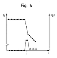
- the course of the detected distances d i as a function of the angle ⁇ i is in Fig. 4 again shown schematically.
- the distances d i corresponding to the object points 26 are initially substantially constant and then abruptly drop at the angle ⁇ j to the distance d j, and from there further to the distance d j + 1 corresponding to the object point 28 'at the left corner of the object 24 corresponds. Due to the oblique position of the object 24 relative to the laser scanner 10, the distances d i then fall further for the following angles ⁇ i .
- the amount of element gradient g i is in Fig. 4 also shown schematically.
- a strong increase in the gradient can be recognized.
- the raw data element with the angle ⁇ j is regarded as a candidate for a virtual object point.
- the amount of change of the Elementgradienten will continue g i for the exceeding of a second threshold value s h studied. More precisely, it is checked if G i - G i - 1 > H s and G j + 2 - G j + 1 > H s is.
- step S14 After completing this correction of ghost measurements in step S12, in step S14 (see FIG. Fig. 2 ) a transformation of the polar coordinates in the raw data elements in Cartesian coordinates, in order then to make in a simpler manner in step S16 corrections caused by movements of the laser scanner 10 or the objects 16 or 18 shifts.
- the vehicle longitudinal axis is selected as the y-axis
- the axis perpendicular to the vehicle longitudinal axis is selected by the laser scanner 10 as the x-axis perpendicular thereto.
- step S16 errors in the positions of the raw data elements caused by movements of the laser scanner 10 and the objects 16 and 18 during a scan are corrected.
- the laser scanner scans the viewing area in 2 ⁇ N + 1 steps, where N is a natural number, for example 180.
- N is a natural number, for example 180.
- the time of detection of the raw data element in step N + 1 is selected in order to minimize errors in the correction caused by deviations of the movements of the laser scanner 10 and / or the articles 16 or 18 be caused by a straightforward and uniform motion.
- the vectorial speed for the laser scanner 10 is read. This speed is determined by a corresponding, in Fig. 1 not shown speed sensor of the motor vehicle 12, taking into account the position of the laser scanner 10 relative to the motor vehicle 12 determined. In a simple approximation, the speed of the laser scanner 10 may be given by the vehicle speed without taking into account the location of the laser scanner 10.
- an object recognition and tracking is carried out in which, for example by means of a Kalman filter and suitable models for the movement of detected objects, estimated values for kinematic data of the detected objects are determined , In addition to the positions, these kinematic data include the speeds of the detected objects. Furthermore, the assignment of the raw data elements to the respective object is stored in this object recognition and / or tracking.
- step S10 this assignment is used to assign the raw data elements as kinematic data the speed of the objects detected in the previous iteration.
- the coordinates of the raw data element i are then shifted by the vector resulting from the multiplication of the time difference previously determined for the raw data element i and the sum of the velocity vector corresponding to the proper motion of the laser scanner 10 and the velocity vector associated with the raw data element i.
- step S18 the actual segment formation is performed.
- the basis of the segment formation is the raw data elements corrected for any virtual object points and for the errors caused by movements during a scan.
- the distance d ij G 1 - G ⁇ x i - x j 2 + G ⁇ y i - y j 2 calculated, in which the distances in the x- or y-direction are weighted differently by the weighting parameter g selectable between 0 and 1.
- g 0.5, ie differences in the coordinates in the x and y directions are equally weighted.
- a segment results from a set of raw data elements, each of which has a distance from at least one other raw data element of the set that is smaller than the separation parameter D.
- the separation parameter D and the weighting parameter g are used in this example.
- step S20 segment properties are calculated for these segments. This is in particular the geometric center of gravity of the coordinates of the raw data elements forming a segment to the number of raw data elements forming the segment, an average "age" of the segments resulting from the average of the acquisition times of the raw data elements forming the segment , and by a width or length of the segment.
- the width and the length of the segment result in this embodiment of the rectangle smallest width and smallest length, which contains all raw data elements, or their coordinates.
- step S22 the thus calculated segment properties are stored or optionally output.
- step S24 the above-mentioned object recognition and tracking is performed on the basis of these segments.
- the segmentation parameters that is to say the separation parameter D and / or the weighting parameter g, are adapted adaptively to the driving situation.
- the procedure is in Fig. 5 shown schematically, wherein the same reference numerals are used for the same steps.
- values of vehicle parameters e.g. B. the steering angle and the speed of the vehicle 12, read in and adjust the segmentation parameters D and g using a heuristic accordingly.
- a maneuvering situation for example in a parking lot, and a motorway journey.
- the maneuvering situation is characterized in that at very low speeds, for example below 10 km / h, large steering angles, for example above 15 °, occur.
- highway driving is characterized by high speeds, For example, about 80 km / h, and small amounts of steering angle, for example, below 10 °, off.
- the separation parameter D is set to a very small distance, for example 30 cm, and the weighting parameter g is set to the value 0.5 so that a very good separation between segments is uniformly achieved in all directions.
- the weighting parameter g is set in this case, for example, the value 0.8, so that in the above formula for the distance between two raw data elements i and j, d ij (g), the distances in the y-direction, ie perpendicular to the vehicle longitudinal axis and direction, are weighted much more.
- the low weighting of the distances in the x-direction has the additional advantage that raw data elements that are detected on one longitudinal side of a vehicle and are far away from each other due to the perspective of the laser scanner 10, can still be combined into one segment.
- the separation parameter D is set to a greater value in order to avoid too high a resolution into different segments, as may occur, for example, when a truck is detected at the level of the axle.
- the separation parameter D is set to the value of 1 m.
- a method according to a third preferred embodiment of the invention in addition to the method according to the first embodiment of the invention in the segmentation reflectivities of object points are taken into account.
- the method for this corresponds to the method described for the first embodiment, but using raw data elements that contain a reflectivity value for each object point.
- the raw data elements which replace the raw data element corresponding to a virtual object point are each assigned the reflectivities of the raw data elements whose coordinates also serve to determine the coordinates of the substitute raw data elements.
- the segments formation corresponding to step S18 as further relationships between raw data elements, the amounts of the differences between the reflectivities R i and R j of raw data elements i and j calculated and compared with a threshold R s .
- the segmentation parameters therefore include the separation parameter D, the weighting parameter g and the threshold value R s .
- Two points are assigned to a segment only if both the criterion for the distances, that is d ij (g) ⁇ D, and at the same time the criterion for the reflectivities, that is
- This has the consequence, in particular, that persons standing very close to a wall can be separated from the wall during segmentation, since the raw data elements assigned to them have a different reflectivity than the raw data elements of the wall behind, while otherwise due to the small geometric distances the raw data elements of wall and person would be combined into one segment.
- step S20 ' In the calculation of the segment properties in step S20 ', in addition to the properties already mentioned above, an average reflectivity is calculated for each segment, which results as an average over the reflectivities of the raw data elements that form the segment.
- inclination data acquired by the laser scanner 10 are contained in the raw data elements.
- the inclination data is the inclination of the object surface in the region of the object corresponding to a raw data element, relative to the direction of the scanning radiation beam.
- both an average slope of the segment calculated as the mean value of the slope data and a variation of the slope data calculated as the standard deviation may be determined from the calculated average. This makes it easier for certain segments to detect certain types of objects, such as lane ramps.
- a different weighting in the two coordinate directions can be achieved in that the ratio of D x to D y is not set to the value 1, but for example in the case of a highway D y is chosen to be much smaller than D x .
Claims (26)
- Procédé pour traiter une image à résolution en profondeur d'une zone de surveillance, qui a été prise par un détecteur de rayonnement électromagnétique, en particulier par un scanneur laser (10), lors d'un balayage d'une zone de vision (14) et qui inclut des éléments de données brutes, qui correspondent à des points (19, 26, 28, 28') sur des objets (16, 18, 22, 24) dans la zone de surveillance et qui incluent des coordonnées des positions des points d'objet (19, 26, 28, 28'), dans lequel on détermine des relations entre les éléments de données brutes et on réunit en un ou en plusieurs segments les éléments de données brutes suivant au moins un critère donné en se basant sur lesdites relations, les relations et/ou le critère dépendant d'au moins un paramètre de segmentation,
caractérisé en ce que
les éléments de données brutes incluent la position d'un point d'objet (19, 26, 28, 28') et sa réflectivité, et en ce que pour la segmentation, les relations entre les éléments de données brutes présentent des différences quant aux réflectivités de deux points d'objet respectifs. - Procédé selon la revendication 1,
caractérisé en ce que
l'on utilise à titre d'autre paramètre de segmentation une différence maximale de réflectivité, et
en ce que l'un des éléments de données brutes n'est associé à un segment que lorsqu'il satisfait à au moins un critère pour au moins une distance élément-élément par rapport à au moins un autre élément de données brutes à associer au segment, et lorsque les réflectivités de l'élément de données brutes et de l'autre élément de données brutes diffèrent de moins de la différence maximale de réflectivité. - Procédé selon la revendication 1 ou 2,
caractérisé en ce que
les éléments de données brutes incluent un angle d'inclinaison qui correspond à un angle entre l'axe du faisceau de rayons détecté par le détecteur et la normale à une surface d'un objet qui a réfléchi le faisceau de rayons, et en ce que l'on associe à un segment, à titre de caractéristique de segment, un angle d'inclinaison qui est déterminé en fonction des angles d'inclinaison des éléments de données brutes constituant le segment. - Procédé selon l'une des revendications précédentes,
caractérisé en ce que
les relations entre les éléments de données brutes incluent des distances tridimensionnelles élément-élément des positions de deux éléments respectifs de données brutes,
en ce que l'on ne constate une appartenance d'un élément de données brutes à un segment que lorsque la distance élément-élément au moins entre la position de l'élément de données brutes et la position d'au moins un autre élément de données brutes à associer au segment passe au-dessous de la valeur d'un paramètre de segmentation correspondant. - Procédé selon la revendication 4,
caractérisé en ce que
pour déterminer la distance élément-élément de deux éléments de données brutes, on applique une fonction de distance des différences de coordonnées des éléments de données brutes et, à titre d'autre paramètre de segmentation, on utilise un paramètre de pondération, les différences étant pondérées les unes par rapport aux autres via le paramètre de pondération. - Procédé selon l'une des revendications 1 à 3,
caractérisé en ce que
les relations entre les éléments de données brutes incluent deux distances élément-élément des positions de deux éléments respectifs de données brutes, qui se réfèrent respectivement à l'une des coordonnées des éléments de données brutes et auxquelles est associé respectivement un autre paramètre de segmentation, et
en ce que l'on ne constante une appartenance d'un élément de données brutes à un segment que lorsque les deux distances élément-élément entre les positions de l'élément de données brutes et la position d'au moins un autre élément de données brutes à associer au segment passe au-dessous des valeurs du paramètre de segmentation correspondant. - Procédé selon l'une des revendications précédentes,
caractérisé en ce que
au moins un paramètre de segmentation dépend de la distance de la position de l'un au moins des deux éléments de données brutes utilisés lors de la détermination de la relation entre deux éléments de données brutes par rapport au détecteur (10) et/ou de la direction de la position par rapport à un axe donné passant par le détecteur. - Procédé selon l'une des revendications 4 à 7,
caractérisé en ce que
un axe est associé au détecteur (10), et en ce que par le choix d'au moins un paramètre de segmentation correspondant, on tient compte des différences de position dans la direction de l'axe moins fortement que dans une direction perpendiculaire à l'axe. - Procédé selon l'une des revendications précédentes,
caractérisé en ce que
l'un au moins des paramètres de segmentation est adapté en fonction de la situation. - Procédé selon la revendication 9,
caractérisé en ce que
l'on détermine un mouvement réel ou un mouvement approximativement réel du détecteur (10), et
en ce que l'un au moins des paramètres de segmentation est adapté en utilisant la vitesse du détecteur (10). - Procédé selon l'une des revendications précédentes,
caractérisé en ce que
l'on utilise une image qui a été obtenue par saisie consécutive des éléments de données brutes lors d'un balayage de la zone de vision (14) du détecteur (10),
et en ce qu'avant la formation de segment, on corrige la position des éléments de données brutes respectivement en fonction du mouvement réel ou d'un mouvement approximativement réel du détecteur et de la différence entre les instants de détection des éléments respectifs de données brutes et un instant de référence. - Procédé selon l'une des revendications précédentes,
caractérisé en ce que
l'on utilise des images qui ont été obtenues par saisie consécutive des éléments de données brutes lors d'un balayage de la zone de vision (14) du détecteur (10),
en ce que l'on saisit une succession d'images et on procède à une reconnaissance d'objet et/ou à une poursuite d'objet en se basant sur les éléments de données brutes des images, en associant à chaque objet reconnu des éléments de données brutes et en associant à chacun de ces éléments dé données brutes, lors de la poursuite d'objet, des données de mouvement calculés,
et ce qu'avant la formation de segment, on corrige les positions des éléments de données brutes en utilisant les résultats de la reconnaissance d'objet et/ou de la poursuite d'objet. - Procédé selon la revendication 12,
caractérisé en ce que
lors de la correction, on corrige les coordonnées des éléments de données brutes en correspondance des données de mouvement qui leur sont associées et en correspondance de la différence entre l'instant de saisie des éléments de données brutes et un instant de référence. - Procédé selon l'une des revendications 10 à 13,
caractérisé en ce que
l'instant de référence se situe entre l'instant le plus précoce défini comme étant l'instant de détection d'un élément de données brutes d'un balayage, et le dernier instant temporel défini comme étant l'instant de détection d'un élément de données brutes du balayage. - Procédé selon l'une des revendications précédentes,
caractérisé en ce que
pour la reconnaissance d'un élément de données brutes correspondant à un point d'objet virtuel (32), dans une plage angulaire donnée de la zone de vision, élément qui a été obtenu par une détection simultanée de deux objets situés l'un derrière l'autre dans l'image, on applique un filtre à gradients aux éléments de données brutes situés dans la plage angulaire, filtre qui utilise respectivement des gradients d'élément associés aux éléments de données brutes, qui correspondent à des gradients de la distance radiale entre la position des éléments de données brutes et le détecteur par rapport à l'angle de la position vis-à-vis d'un axe donné passant par le détecteur. - Procédé selon la revendication 15,
caractérisé en ce que
l'on détermine les gradients d'élément par formation de la différence de deux valeurs de distance qui se succèdent par référence aux angles, et
en ce que l'on ne détermine un élément de données brutes correspondant à un point d'objet virtuel (32) que lorsque la valeur d'un gradient d'élément qui a été déterminé en utilisant l'élément de données brutes, passe au-dessus d'une première valeur seuil et que la modification des gradients d'élément des valeurs de distance d'éléments de données brutes successives voisines de l'élément de données brutes est supérieure à une seconde valeur seuil ou que pour cet élément de données brutes, la valeur de la modification du gradient d'élément passe au-dessus d'une valeur seuil. - Procédé selon la revendication 15 ou 16,
caractérisé en ce que
l'on élimine de l'ensemble d'éléments de donnés brutes un élément de données brutes qui correspond à un point d'objet virtuel (32). - Procédé selon la revendication 15 ou 16,
caractérisé en ce que
l'on substitue à un élément de données brutes qui correspond à un point d'objet virtuel (32) au moins un élément de données brutes qui présente le même angle, en associant à l'élément de données brutes, à titre de distance, une distance déterminée à partir d'au moins un élément de données brutes, voisin quant à l'angle, présentant un angle plus petit ou plus grand. - Procédé selon la revendication 18,
caractérisé en ce que
l'on détermine la distance à associer par extrapolation des distances des éléments de données brutes voisins. - Procédé selon l'une des revendications 15 à 19,
caractérisé en ce que
les éléments de données brutes incluent des valeurs de réflectivité, et pour déterminer un point d'objet virtuel, on utilise des gradients des réflectivités. - Procédé selon l'une des revendications précédentes,
caractérisé en ce que
pour au moins un segment, on détermine plusieurs, de préférence au moins quatre propriétés, et on les associe à celui-ci, les propriétés étant choisies parmi le groupe contenant les coordonnées d'un point de référence, en particulier du centre de gravité, du segment, la largeur du segment, la longueur du segment, la réflectivité du segment, l'angle d'inclinaison du segment, le nombre d'éléments de données brutes du segment et l'âge du segment. - Procédé selon l'une des revendications précédentes,
caractérisé en ce que
les éléments de données brutes incluent une information relative à la hauteur, et en ce que l'on utilise l'information relative à la hauteur pour la segmentation. - Procédé selon l'une des revendications précédentes,
caractérisé en ce que
les éléments de données brutes incluent une information relative à la hauteur, et en ce que l'on détermine une hauteur de segment pour un segment à titre de propriété en fonction des hauteurs des éléments de données brutes constituant ce segment, et on l'associe à celui-ci. - Programme d'ordinateur comprenant des moyens formant code de programme pour mettre en oeuvre le procédé selon l'une des revendications 1 à 23, lorsque le programme est exécuté sur un ordinateur.
- Produit de programme d'ordinateur comprenant des moyens formant code de programme qui sont mémorisés sur un support de données lisible à l'ordinateur pour mettre en oeuvre le procédé selon l'une des revendications 1 à 23, lorsque le produit de programme est exécuté sur un ordinateur.
- Dispositif pour générer un modèle d'une zone de surveillance comportant au moins un détecteur de rayonnement électromagnétique, en particulier un scanneur laser (10), dont la zone de vision (14) inclut la zone de surveillance, et comportant un système de traitement de données qui- est réalisé pour mettre en oeuvre un procédé pour le traitement d'une image de préférence à résolution en profondeur de la zone de surveillance, qui a été prise lors d'un balayage de la zone de vision (14) du détecteur et qui inclut des éléments de données brutes qui correspondent à des points (19, 26, 28, 28') sur des objets (16, 18, 22, 24) dans la zone de surveillance et qui incluent des coordonnées des positions des points d'objet (19, 26, 28, 28') et leurs réflectivité, et- qui comprend des moyens pour déterminer des relations entre les éléments de données brutes qui, pour la segmentation, présentent des différences quant aux réflectivités de deux points d'objet respectifs, et des moyens pour réunir en un ou en plusieurs segments les éléments de données brutes suivant au moins un critère donné en se basant sur lesdites relations, les relations et/ou le critère dépendant d'au moins un paramètre de segmentation.
Applications Claiming Priority (8)
| Application Number | Priority Date | Filing Date | Title |
|---|---|---|---|
| DE10128954 | 2001-06-15 | ||
| DE10128954A DE10128954A1 (de) | 2001-06-15 | 2001-06-15 | Korrekturverfahren für Daten mehrerer optoelektronischer Sensoren |
| DE10132335A DE10132335A1 (de) | 2001-07-04 | 2001-07-04 | Verfahren und Vorrichtung zur Lokalisierung von Objekten im Raum |
| DE10132335 | 2001-07-04 | ||
| DE10148062A DE10148062A1 (de) | 2001-09-28 | 2001-09-28 | Verfahren zur Verarbeitung eines tiefenaufgelösten Bildes |
| DE10148062 | 2001-09-28 | ||
| DE10154861A DE10154861A1 (de) | 2001-11-08 | 2001-11-08 | Verfahren zur Bereitstellung von Bildinformationen |
| DE10154861 | 2001-11-08 |
Publications (2)
| Publication Number | Publication Date |
|---|---|
| EP1267178A1 EP1267178A1 (fr) | 2002-12-18 |
| EP1267178B1 true EP1267178B1 (fr) | 2008-08-20 |
Family
ID=27437982
Family Applications (4)
| Application Number | Title | Priority Date | Filing Date |
|---|---|---|---|
| EP02751031A Expired - Lifetime EP1405100B1 (fr) | 2001-06-15 | 2002-06-14 | Procede de correction de donnees relatives a plusieurs capteurs optoelectroniques |
| EP02743204A Withdrawn EP1395852A1 (fr) | 2001-06-15 | 2002-06-14 | Procede pour preparer des informations imagees |
| EP02013171A Ceased EP1267177A1 (fr) | 2001-06-15 | 2002-06-14 | Procédé et dispositif pour la localisation d'objets dans l'espace |
| EP02013172A Expired - Lifetime EP1267178B1 (fr) | 2001-06-15 | 2002-06-14 | Procédé de traitement d'une image à haute définition |
Family Applications Before (3)
| Application Number | Title | Priority Date | Filing Date |
|---|---|---|---|
| EP02751031A Expired - Lifetime EP1405100B1 (fr) | 2001-06-15 | 2002-06-14 | Procede de correction de donnees relatives a plusieurs capteurs optoelectroniques |
| EP02743204A Withdrawn EP1395852A1 (fr) | 2001-06-15 | 2002-06-14 | Procede pour preparer des informations imagees |
| EP02013171A Ceased EP1267177A1 (fr) | 2001-06-15 | 2002-06-14 | Procédé et dispositif pour la localisation d'objets dans l'espace |
Country Status (6)
| Country | Link |
|---|---|
| US (1) | US7570793B2 (fr) |
| EP (4) | EP1405100B1 (fr) |
| JP (2) | JP2004530144A (fr) |
| AT (2) | ATE405853T1 (fr) |
| DE (2) | DE50212810D1 (fr) |
| WO (2) | WO2002103385A1 (fr) |
Families Citing this family (99)
| Publication number | Priority date | Publication date | Assignee | Title |
|---|---|---|---|---|
| US6124886A (en) | 1997-08-25 | 2000-09-26 | Donnelly Corporation | Modular rearview mirror assembly |
| US6326613B1 (en) | 1998-01-07 | 2001-12-04 | Donnelly Corporation | Vehicle interior mirror assembly adapted for containing a rain sensor |
| US8288711B2 (en) | 1998-01-07 | 2012-10-16 | Donnelly Corporation | Interior rearview mirror system with forwardly-viewing camera and a control |
| US6445287B1 (en) | 2000-02-28 | 2002-09-03 | Donnelly Corporation | Tire inflation assistance monitoring system |
| US6278377B1 (en) | 1999-08-25 | 2001-08-21 | Donnelly Corporation | Indicator for vehicle accessory |
| US6420975B1 (en) | 1999-08-25 | 2002-07-16 | Donnelly Corporation | Interior rearview mirror sound processing system |
| WO2001064481A2 (fr) | 2000-03-02 | 2001-09-07 | Donnelly Corporation | Systeme de miroir video integrant un module accessoire |
| US7480149B2 (en) | 2004-08-18 | 2009-01-20 | Donnelly Corporation | Accessory module for vehicle |
| US6396408B2 (en) | 2000-03-31 | 2002-05-28 | Donnelly Corporation | Digital electrochromic circuit with a vehicle network |
| WO2003065084A1 (fr) | 2002-01-31 | 2003-08-07 | Donnelly Corporation | Module d'accessoires de vehicule |
| DE10312249A1 (de) * | 2003-03-19 | 2004-09-30 | Ibeo Automobile Sensor Gmbh | Verfahren zur gemeinsamen Verarbeitung von tiefenaufgelösten Bildern und Videobildern |
| DE10312611A1 (de) * | 2003-03-21 | 2004-09-30 | Daimlerchrysler Ag | Verfahren und Vorrichtung zum Erfassen eines Objekts im Umfeld eines Kraftfahrzeugs |
| DE10325709A1 (de) * | 2003-06-06 | 2004-12-23 | Valeo Schalter Und Sensoren Gmbh | Vorrichtung und Verfahren zum Erkennen des Konturverlaufes eines Hindernisses |
| DE10336638A1 (de) | 2003-07-25 | 2005-02-10 | Robert Bosch Gmbh | Vorrichtung zur Klassifizierung wengistens eines Objekts in einem Fahrzeugumfeld |
| JP3941765B2 (ja) | 2003-09-11 | 2007-07-04 | トヨタ自動車株式会社 | 物体検出装置 |
| US7047132B2 (en) * | 2004-01-12 | 2006-05-16 | Steven Jacobs | Mobile vehicle sensor array |
| ES2429572T3 (es) | 2004-12-01 | 2013-11-15 | Zorg Industries (Hong Kong) Limited | Sistema integrado de vehículos para la prevención de colisiones a baja velocidad |
| WO2006063827A1 (fr) | 2004-12-15 | 2006-06-22 | Magna Donnelly Electronics Naas Limited | Systeme module accessoire pour fenetre d'un vehicule |
| USRE46672E1 (en) | 2006-07-13 | 2018-01-16 | Velodyne Lidar, Inc. | High definition LiDAR system |
| DE102006057277A1 (de) * | 2006-12-05 | 2008-06-12 | Robert Bosch Gmbh | Verfahren zum Betrieb eines Radarsystems bei möglicher Zielobjektverdeckung sowie Radarsystem zur Durchführung des Verfahrens |
| US8662397B2 (en) * | 2007-09-27 | 2014-03-04 | Symbol Technologies, Inc. | Multiple camera imaging-based bar code reader |
| JP5136927B2 (ja) * | 2007-10-09 | 2013-02-06 | オプテックス株式会社 | レーザエリアセンサ |
| US20100001075A1 (en) * | 2008-07-07 | 2010-01-07 | Symbol Technologies, Inc. | Multi-imaging scanner for reading images |
| US8570374B2 (en) | 2008-11-13 | 2013-10-29 | Magna Electronics Inc. | Camera for vehicle |
| US8415609B2 (en) * | 2009-01-31 | 2013-04-09 | Keyence Corporation | Safety photoelectric switch |
| US8717225B2 (en) | 2009-07-31 | 2014-05-06 | Honda Motor Co., Ltd. | Object detection device for vehicle and object detection method for vehicle |
| DE202010012985U1 (de) | 2010-11-25 | 2012-02-27 | Sick Ag | Sensoranordnung zur Objekterkennung |
| DE102010060942A1 (de) | 2010-12-01 | 2012-06-06 | Sick Ag | Sensoranordnung zur Objekterkennung |
| RU2468382C1 (ru) * | 2011-05-24 | 2012-11-27 | Открытое Акционерное Общество "Производственное Объединение "Уральский Оптико-Механический Завод" Имени Э.С. Яламова" (Оао "По "Уомз") | Способ формирования сигнала управления в следящей системе |
| US8885151B1 (en) | 2012-09-04 | 2014-11-11 | Google Inc. | Condensing sensor data for transmission and processing |
| JP6019959B2 (ja) * | 2012-09-06 | 2016-11-02 | 富士通株式会社 | 物体検出装置、物体検出プログラムおよび車両 |
| US10557939B2 (en) | 2015-10-19 | 2020-02-11 | Luminar Technologies, Inc. | Lidar system with improved signal-to-noise ratio in the presence of solar background noise |
| WO2017079483A1 (fr) | 2015-11-05 | 2017-05-11 | Luminar Technologies, Inc. | Système lidar avec vitesse de balayage améliorée pour cartographie de profondeur haute résolution |
| WO2017095817A1 (fr) | 2015-11-30 | 2017-06-08 | Luminar Technologies, Inc. | Système lidar avec laser distribué et plusieurs têtes de détection et laser pulsé pour système lidar |
| US10627490B2 (en) | 2016-01-31 | 2020-04-21 | Velodyne Lidar, Inc. | Multiple pulse, LIDAR based 3-D imaging |
| CN109154661A (zh) | 2016-03-19 | 2019-01-04 | 威力登激光雷达有限公司 | 用于基于lidar的3-d成像的集成照射和检测 |
| US10429496B2 (en) | 2016-05-27 | 2019-10-01 | Analog Devices, Inc. | Hybrid flash LIDAR system |
| CA3024510C (fr) | 2016-06-01 | 2022-10-04 | Velodyne Lidar, Inc. | Lidar a balayage a pixels multiples |
| US10942257B2 (en) | 2016-12-31 | 2021-03-09 | Innovusion Ireland Limited | 2D scanning high precision LiDAR using combination of rotating concave mirror and beam steering devices |
| US9905992B1 (en) | 2017-03-16 | 2018-02-27 | Luminar Technologies, Inc. | Self-Raman laser for lidar system |
| US9810775B1 (en) | 2017-03-16 | 2017-11-07 | Luminar Technologies, Inc. | Q-switched laser for LIDAR system |
| US9810786B1 (en) | 2017-03-16 | 2017-11-07 | Luminar Technologies, Inc. | Optical parametric oscillator for lidar system |
| US9869754B1 (en) | 2017-03-22 | 2018-01-16 | Luminar Technologies, Inc. | Scan patterns for lidar systems |
| US10209359B2 (en) | 2017-03-28 | 2019-02-19 | Luminar Technologies, Inc. | Adaptive pulse rate in a lidar system |
| US10267899B2 (en) | 2017-03-28 | 2019-04-23 | Luminar Technologies, Inc. | Pulse timing based on angle of view |
| US10254388B2 (en) | 2017-03-28 | 2019-04-09 | Luminar Technologies, Inc. | Dynamically varying laser output in a vehicle in view of weather conditions |
| US10114111B2 (en) | 2017-03-28 | 2018-10-30 | Luminar Technologies, Inc. | Method for dynamically controlling laser power |
| US11119198B2 (en) | 2017-03-28 | 2021-09-14 | Luminar, Llc | Increasing operational safety of a lidar system |
| US10007001B1 (en) | 2017-03-28 | 2018-06-26 | Luminar Technologies, Inc. | Active short-wave infrared four-dimensional camera |
| US10732281B2 (en) | 2017-03-28 | 2020-08-04 | Luminar Technologies, Inc. | Lidar detector system having range walk compensation |
| US10139478B2 (en) | 2017-03-28 | 2018-11-27 | Luminar Technologies, Inc. | Time varying gain in an optical detector operating in a lidar system |
| US10121813B2 (en) | 2017-03-28 | 2018-11-06 | Luminar Technologies, Inc. | Optical detector having a bandpass filter in a lidar system |
| US10545240B2 (en) | 2017-03-28 | 2020-01-28 | Luminar Technologies, Inc. | LIDAR transmitter and detector system using pulse encoding to reduce range ambiguity |
| US10061019B1 (en) | 2017-03-28 | 2018-08-28 | Luminar Technologies, Inc. | Diffractive optical element in a lidar system to correct for backscan |
| US10088559B1 (en) | 2017-03-29 | 2018-10-02 | Luminar Technologies, Inc. | Controlling pulse timing to compensate for motor dynamics |
| US10976417B2 (en) | 2017-03-29 | 2021-04-13 | Luminar Holdco, Llc | Using detectors with different gains in a lidar system |
| US10663595B2 (en) | 2017-03-29 | 2020-05-26 | Luminar Technologies, Inc. | Synchronized multiple sensor head system for a vehicle |
| US10191155B2 (en) | 2017-03-29 | 2019-01-29 | Luminar Technologies, Inc. | Optical resolution in front of a vehicle |
| US10254762B2 (en) | 2017-03-29 | 2019-04-09 | Luminar Technologies, Inc. | Compensating for the vibration of the vehicle |
| US10969488B2 (en) | 2017-03-29 | 2021-04-06 | Luminar Holdco, Llc | Dynamically scanning a field of regard using a limited number of output beams |
| US11181622B2 (en) | 2017-03-29 | 2021-11-23 | Luminar, Llc | Method for controlling peak and average power through laser receiver |
| US11002853B2 (en) | 2017-03-29 | 2021-05-11 | Luminar, Llc | Ultrasonic vibrations on a window in a lidar system |
| US10983213B2 (en) | 2017-03-29 | 2021-04-20 | Luminar Holdco, Llc | Non-uniform separation of detector array elements in a lidar system |
| US10641874B2 (en) | 2017-03-29 | 2020-05-05 | Luminar Technologies, Inc. | Sizing the field of view of a detector to improve operation of a lidar system |
| US10684360B2 (en) | 2017-03-30 | 2020-06-16 | Luminar Technologies, Inc. | Protecting detector in a lidar system using off-axis illumination |
| US10241198B2 (en) | 2017-03-30 | 2019-03-26 | Luminar Technologies, Inc. | Lidar receiver calibration |
| US10401481B2 (en) | 2017-03-30 | 2019-09-03 | Luminar Technologies, Inc. | Non-uniform beam power distribution for a laser operating in a vehicle |
| US10295668B2 (en) | 2017-03-30 | 2019-05-21 | Luminar Technologies, Inc. | Reducing the number of false detections in a lidar system |
| US9989629B1 (en) | 2017-03-30 | 2018-06-05 | Luminar Technologies, Inc. | Cross-talk mitigation using wavelength switching |
| US11022688B2 (en) | 2017-03-31 | 2021-06-01 | Luminar, Llc | Multi-eye lidar system |
| US20180284246A1 (en) | 2017-03-31 | 2018-10-04 | Luminar Technologies, Inc. | Using Acoustic Signals to Modify Operation of a Lidar System |
| US10386465B2 (en) | 2017-03-31 | 2019-08-20 | Velodyne Lidar, Inc. | Integrated LIDAR illumination power control |
| US10677897B2 (en) | 2017-04-14 | 2020-06-09 | Luminar Technologies, Inc. | Combining lidar and camera data |
| JP2020519881A (ja) | 2017-05-08 | 2020-07-02 | ベロダイン ライダー, インク. | Lidarデータ収集及び制御 |
| DE102017118156A1 (de) | 2017-08-09 | 2019-02-14 | Valeo Schalter Und Sensoren Gmbh | Verfahren zum Überwachen eines Umgebungsbereiches eines Kraftfahrzeugs, Sensorsteuergerät, Fahrerassistenzsystem sowie Kraftfahrzeug |
| US10211593B1 (en) | 2017-10-18 | 2019-02-19 | Luminar Technologies, Inc. | Optical amplifier with multi-wavelength pumping |
| US10451716B2 (en) | 2017-11-22 | 2019-10-22 | Luminar Technologies, Inc. | Monitoring rotation of a mirror in a lidar system |
| US10571567B2 (en) | 2017-11-22 | 2020-02-25 | Luminar Technologies, Inc. | Low profile lidar scanner with polygon mirror |
| US11294041B2 (en) | 2017-12-08 | 2022-04-05 | Velodyne Lidar Usa, Inc. | Systems and methods for improving detection of a return signal in a light ranging and detection system |
| US11493601B2 (en) | 2017-12-22 | 2022-11-08 | Innovusion, Inc. | High density LIDAR scanning |
| WO2020013890A2 (fr) | 2018-02-23 | 2020-01-16 | Innovusion Ireland Limited | Orientation d'impulsions à longueurs d'onde multiples dans des systèmes lidar |
| US10578720B2 (en) | 2018-04-05 | 2020-03-03 | Luminar Technologies, Inc. | Lidar system with a polygon mirror and a noise-reducing feature |
| US11029406B2 (en) | 2018-04-06 | 2021-06-08 | Luminar, Llc | Lidar system with AlInAsSb avalanche photodiode |
| FR3080922B1 (fr) * | 2018-05-03 | 2020-09-18 | Transdev Group | Dispositif electronique et procede de detection d'un objet via un lidar a balayage, vehicule automobile autonome et programme d'ordinateur associes |
| DE102018110775A1 (de) * | 2018-05-04 | 2019-11-07 | Valeo Schalter Und Sensoren Gmbh | Verfahren zum Bestimmen einer Ausrichtung eines optoelektronischen Sensors mittels Abtastpunkten eines Sensorbildes sowie optoelektronischer Sensor |
| US10348051B1 (en) | 2018-05-18 | 2019-07-09 | Luminar Technologies, Inc. | Fiber-optic amplifier |
| US10591601B2 (en) | 2018-07-10 | 2020-03-17 | Luminar Technologies, Inc. | Camera-gated lidar system |
| US10627516B2 (en) | 2018-07-19 | 2020-04-21 | Luminar Technologies, Inc. | Adjustable pulse characteristics for ground detection in lidar systems |
| US10551501B1 (en) | 2018-08-09 | 2020-02-04 | Luminar Technologies, Inc. | Dual-mode lidar system |
| US10340651B1 (en) | 2018-08-21 | 2019-07-02 | Luminar Technologies, Inc. | Lidar system with optical trigger |
| US11971507B2 (en) | 2018-08-24 | 2024-04-30 | Velodyne Lidar Usa, Inc. | Systems and methods for mitigating optical crosstalk in a light ranging and detection system |
| US10712434B2 (en) | 2018-09-18 | 2020-07-14 | Velodyne Lidar, Inc. | Multi-channel LIDAR illumination driver |
| US11082010B2 (en) | 2018-11-06 | 2021-08-03 | Velodyne Lidar Usa, Inc. | Systems and methods for TIA base current detection and compensation |
| US11885958B2 (en) | 2019-01-07 | 2024-01-30 | Velodyne Lidar Usa, Inc. | Systems and methods for a dual axis resonant scanning mirror |
| US11774561B2 (en) | 2019-02-08 | 2023-10-03 | Luminar Technologies, Inc. | Amplifier input protection circuits |
| CN111745635B (zh) * | 2019-03-28 | 2022-03-04 | 苏州科瓴精密机械科技有限公司 | 识别反光标方法、移动机器人定位方法及移动机器人系统 |
| US10613203B1 (en) | 2019-07-01 | 2020-04-07 | Velodyne Lidar, Inc. | Interference mitigation for light detection and ranging |
| US11556000B1 (en) | 2019-08-22 | 2023-01-17 | Red Creamery Llc | Distally-actuated scanning mirror |
| JP2021148746A (ja) * | 2020-03-23 | 2021-09-27 | 株式会社リコー | 測距装置及び測距方法 |
Family Cites Families (43)
| Publication number | Priority date | Publication date | Assignee | Title |
|---|---|---|---|---|
| DE2021566A1 (de) | 1970-05-02 | 1971-11-25 | Ibm Deutschland | Anordnung zur raeumlichen und zeitlichen Modulation eines Lichtstrahles |
| JPS5843009A (ja) * | 1981-09-07 | 1983-03-12 | Toyota Motor Corp | 自動車速制御装置 |
| DE3832720A1 (de) | 1988-09-27 | 1990-03-29 | Bosch Gmbh Robert | Abstandsmesseinrichtung zur beruehrungslosen abstands- und winkelerkennung |
| DE3915631A1 (de) | 1989-05-12 | 1990-11-15 | Dornier Luftfahrt | Navigationsverfahren |
| US5189619A (en) * | 1989-09-05 | 1993-02-23 | Toyota Jidosha Kabushiki Kaisha | AI-based adaptive vehicle control system |
| US5128874A (en) | 1990-01-02 | 1992-07-07 | Honeywell Inc. | Inertial navigation sensor integrated obstacle detection system |
| DE69124726T2 (de) | 1990-10-25 | 1997-07-03 | Mitsubishi Electric Corp | Vorrichtung zur Abstandsdetektion für ein Kraftfahrzeug |
| FR2676284B1 (fr) * | 1991-05-07 | 1994-12-02 | Peugeot | Procede de detection d'obstacles presents devant un vehicule automobile et dispositif pour la mise en óoeuvre d'un tel procede. |
| DE4119180A1 (de) | 1991-06-11 | 1992-12-17 | Merkel Peter Dr | Verfahren und vorrichtung zur vermessung und dokumentation der geometrie, struktur- und materialbeschaffenheit von dreidimensionalen objekten, wie fassaden und raeume sowie deren waende, einrichtungen und installationen |
| DE4142702A1 (de) | 1991-12-21 | 1993-06-24 | Leuze Electronic Gmbh & Co | Einrichtung zum abtasten dreidimensionaler objekte |
| US5756981A (en) * | 1992-02-27 | 1998-05-26 | Symbol Technologies, Inc. | Optical scanner for reading and decoding one- and-two-dimensional symbologies at variable depths of field including memory efficient high speed image processing means and high accuracy image analysis means |
| DE4301538A1 (de) | 1992-03-17 | 1994-07-28 | Peter Dr Ing Brueckner | Verfahren und Anordnung zur berührungslosen dreidimensionalen Messung, insbesondere zur Messung von Gebißmodellen |
| DE4222642A1 (de) * | 1992-07-10 | 1994-01-13 | Bodenseewerk Geraetetech | Bilderfassende Sensoreinheit |
| US5275354A (en) * | 1992-07-13 | 1994-01-04 | Loral Vought Systems Corporation | Guidance and targeting system |
| JP3232724B2 (ja) | 1992-12-08 | 2001-11-26 | 株式会社デンソー | 車間距離制御装置 |
| JP3263699B2 (ja) | 1992-12-22 | 2002-03-04 | 三菱電機株式会社 | 走行環境監視装置 |
| DE4320485B4 (de) | 1993-06-21 | 2007-04-19 | Eads Deutschland Gmbh | Verfahren zur Objektvermessung mittels intelligenter Entfernungsbildkamera |
| JP3183598B2 (ja) | 1993-12-14 | 2001-07-09 | 三菱電機株式会社 | 障害物検知装置 |
| US5635922A (en) | 1993-12-27 | 1997-06-03 | Hyundai Electronics Industries Co., Ltd. | Apparatus for and method of preventing car collision utilizing laser |
| JP3212218B2 (ja) | 1994-05-26 | 2001-09-25 | 三菱電機株式会社 | 車両用障害物検出装置 |
| JP2854805B2 (ja) * | 1994-06-15 | 1999-02-10 | 富士通株式会社 | 物体認識方法および視覚装置 |
| DE4434233A1 (de) | 1994-09-24 | 1995-11-16 | Peter Dr Ing Brueckner | Verfahren und Anordnung zur berührungslosen dreidimensionalen Messung, insbesondere von ungleichförmig bewegten Meßobjekten |
| JPH08122060A (ja) * | 1994-10-21 | 1996-05-17 | Mitsubishi Electric Corp | 車両周辺監視システム |
| JP3498406B2 (ja) | 1995-02-17 | 2004-02-16 | マツダ株式会社 | 自動車の走行制御装置 |
| DE19516324A1 (de) | 1995-04-24 | 1996-10-31 | Gos Ges Zur Foerderung Angewan | Meßverfahren und Anordnung zur Messung der Lage-, Form- und Bewegungsparameter entfernter Objekte |
| JP3230642B2 (ja) * | 1995-05-29 | 2001-11-19 | ダイハツ工業株式会社 | 先行車検出装置 |
| IL114278A (en) | 1995-06-22 | 2010-06-16 | Microsoft Internat Holdings B | Camera and method |
| US5717401A (en) | 1995-09-01 | 1998-02-10 | Litton Systems, Inc. | Active recognition system with optical signal processing |
| JP3336825B2 (ja) * | 1995-09-25 | 2002-10-21 | 三菱自動車工業株式会社 | 障害物認識装置 |
| DE19603267A1 (de) | 1996-01-30 | 1997-07-31 | Bosch Gmbh Robert | Vorrichtung zur Abstands- und/oder Positionsbestimmung |
| DE59802284D1 (de) | 1997-02-20 | 2002-01-17 | Volkswagen Ag | Verfahren und Vorrichtung zum Bestimmen eines Abstandes eines Hindernisses von einem Fahrzeug |
| DE19757840C1 (de) | 1997-12-24 | 1999-09-30 | Johann F Hipp | Vorrichtung zur optischen Erfassung und Abstandermittlung von Objekten von einem Fahrzeug aus |
| US6175652B1 (en) * | 1997-12-31 | 2001-01-16 | Cognex Corporation | Machine vision system for analyzing features based on multiple object images |
| US5966090A (en) * | 1998-03-16 | 1999-10-12 | Mcewan; Thomas E. | Differential pulse radar motion sensor |
| DE19815149A1 (de) | 1998-04-03 | 1999-10-07 | Leuze Electronic Gmbh & Co | Sensoranordnung |
| US5966678A (en) * | 1998-05-18 | 1999-10-12 | The United States Of America As Represented By The Secretary Of The Navy | Method for filtering laser range data |
| US6055490A (en) | 1998-07-27 | 2000-04-25 | Laser Technology, Inc. | Apparatus and method for determining precision reflectivity of highway signs and other reflective objects utilizing an optical range finder instrument |
| JP2000075030A (ja) | 1998-08-27 | 2000-03-14 | Aisin Seiki Co Ltd | スキャン型レーザーレーダ装置 |
| US6573855B1 (en) * | 1998-08-31 | 2003-06-03 | Osaka Gas Co., Ltd. | Three-dimensional questing method, three-dimensional voxel data displaying method, and device therefor |
| DE19910667A1 (de) | 1999-03-11 | 2000-09-21 | Volkswagen Ag | Vorrichtung mit mindestens einem Lasersensor und Verfahren zum Betreiben eines Lasersensors |
| US6662649B1 (en) * | 1999-03-19 | 2003-12-16 | Simmons Sirvey Corporation | Material level monitoring and reporting |
| DE19947766A1 (de) | 1999-10-02 | 2001-05-10 | Bosch Gmbh Robert | Einrichtung zur Überwachung der Umgebung eines einparkenden Fahrzeugs |
| DE10143504A1 (de) * | 2001-09-05 | 2003-03-20 | Sick Ag | Überwachungsverfahren und optoelektronischer Sensor |
-
2002
- 2002-06-14 AT AT02013172T patent/ATE405853T1/de not_active IP Right Cessation
- 2002-06-14 EP EP02751031A patent/EP1405100B1/fr not_active Expired - Lifetime
- 2002-06-14 JP JP2003505649A patent/JP2004530144A/ja not_active Withdrawn
- 2002-06-14 DE DE50212810T patent/DE50212810D1/de not_active Expired - Lifetime
- 2002-06-14 EP EP02743204A patent/EP1395852A1/fr not_active Withdrawn
- 2002-06-14 US US10/480,507 patent/US7570793B2/en active Active
- 2002-06-14 JP JP2003507583A patent/JP4669661B2/ja not_active Expired - Fee Related
- 2002-06-14 DE DE50212663T patent/DE50212663D1/de not_active Expired - Lifetime
- 2002-06-14 EP EP02013171A patent/EP1267177A1/fr not_active Ceased
- 2002-06-14 EP EP02013172A patent/EP1267178B1/fr not_active Expired - Lifetime
- 2002-06-14 WO PCT/EP2002/006599 patent/WO2002103385A1/fr not_active Application Discontinuation
- 2002-06-14 WO PCT/EP2002/006594 patent/WO2003001241A1/fr active IP Right Grant
- 2002-06-14 AT AT02751031T patent/ATE409320T1/de not_active IP Right Cessation
Non-Patent Citations (1)
| Title |
|---|
| DIETMAYER ET AL: "Model based object classification and object tracking in traffic scenes from range images", PROCEEDINGS OF IV 2001, IEEE IVS, May 2001 (2001-05-01), Tokio, Japan, XP009023302 * |
Also Published As
| Publication number | Publication date |
|---|---|
| ATE409320T1 (de) | 2008-10-15 |
| JP2004530902A (ja) | 2004-10-07 |
| JP2004530144A (ja) | 2004-09-30 |
| ATE405853T1 (de) | 2008-09-15 |
| WO2002103385A1 (fr) | 2002-12-27 |
| DE50212810D1 (de) | 2008-11-06 |
| DE50212663D1 (de) | 2008-10-02 |
| EP1395852A1 (fr) | 2004-03-10 |
| JP4669661B2 (ja) | 2011-04-13 |
| EP1405100A1 (fr) | 2004-04-07 |
| WO2003001241A1 (fr) | 2003-01-03 |
| US7570793B2 (en) | 2009-08-04 |
| US20050034036A1 (en) | 2005-02-10 |
| EP1405100B1 (fr) | 2008-09-24 |
| EP1267177A1 (fr) | 2002-12-18 |
| EP1267178A1 (fr) | 2002-12-18 |
Similar Documents
| Publication | Publication Date | Title |
|---|---|---|
| EP1267178B1 (fr) | Procédé de traitement d'une image à haute définition | |
| DE10114932B4 (de) | Dreidimensionale Umfelderfassung | |
| EP1298454B1 (fr) | Procédé de reconnaissance et de suivi d'objets | |
| EP1475764B1 (fr) | Méthode et appareil pour calculer la probabilité d'une collision entre une véhicule et un objet | |
| EP1418444B1 (fr) | Procédé pour déterminer la vitesse de lacet d'un véhicule | |
| EP0691534B1 (fr) | Procédé de détermination de la visibilité, en particulier pour le déplacement d'un véhicule | |
| EP1557691B1 (fr) | Procédé de détection des marquages sur une chaussée | |
| DE102004010197B4 (de) | Verfahren zur Funktionskontrolle einer Positionsermittlungs- oder Umgebungserfassungseinrichtung eines Fahrzeugs oder zur Kontrolle einer digitalen Karte | |
| EP1531343B1 (fr) | Procédé de suivi d'objets | |
| EP1557694B1 (fr) | Procédé de classement d'objets | |
| DE102010012811B4 (de) | Verfahren zur Messung von Geschwindigkeiten und Zuordnung der gemessenen Geschwindigkeiten zu angemessenen Fahrzeugen durch Erfassen und Zusammenführen von Objekt-Trackingdaten und Bild-Trackingdaten | |
| DE102004018813A1 (de) | Verfahren zur Erkennung und/oder Verfolgung von Objekten | |
| WO2004055548A1 (fr) | Procede pour identifier et suivre des objets | |
| EP1531342B1 (fr) | Procédé de détection des piétons | |
| EP1306690B1 (fr) | Procédé de reconnaissance et de suivi d'objets | |
| EP1460454B1 (fr) | Procédé de traitement combiné d'images à haute définition et d'images vidéo | |
| DE10138641A1 (de) | Verfahren zur Bestimmung einer Modellfahrbahn | |
| DE102011077333A1 (de) | Fahrerassistenzsystem mit Objektdetektion | |
| DE10148062A1 (de) | Verfahren zur Verarbeitung eines tiefenaufgelösten Bildes | |
| EP1298012B1 (fr) | Procédé de reconnaissance et de poursuite d'objets | |
| EP4139709A1 (fr) | Procédé et dispositif d'identification de l'efflorescence dans une mesure lidar | |
| EP3531167B1 (fr) | Procédé et dispositif de mesure de distance optique | |
| EP3663881B1 (fr) | Procédé de commande d'un véhicule autonome en fonction des vecteurs de mouvement estimés | |
| EP3885787A1 (fr) | Acquisition de données de mesure de distance | |
| DE102019134985B4 (de) | Verfahren zum Erfassen wenigstens eines Verkehrsteilnehmers |
Legal Events
| Date | Code | Title | Description |
|---|---|---|---|
| PUAI | Public reference made under article 153(3) epc to a published international application that has entered the european phase |
Free format text: ORIGINAL CODE: 0009012 |
|
| AK | Designated contracting states |
Kind code of ref document: A1 Designated state(s): AT BE CH CY DE DK ES FI FR GB GR IE IT LI LU MC NL PT SE TR |
|
| AX | Request for extension of the european patent |
Free format text: AL;LT;LV;MK;RO;SI |
|
| 17P | Request for examination filed |
Effective date: 20030527 |
|
| AKX | Designation fees paid |
Designated state(s): AT BE CH CY DE DK ES FI FR GB GR IE IT LI LU MC NL PT SE TR |
|
| 17Q | First examination report despatched |
Effective date: 20041230 |
|
| GRAP | Despatch of communication of intention to grant a patent |
Free format text: ORIGINAL CODE: EPIDOSNIGR1 |
|
| GRAS | Grant fee paid |
Free format text: ORIGINAL CODE: EPIDOSNIGR3 |
|
| GRAA | (expected) grant |
Free format text: ORIGINAL CODE: 0009210 |
|
| AK | Designated contracting states |
Kind code of ref document: B1 Designated state(s): AT BE CH CY DE DK ES FI FR GB GR IE IT LI LU MC NL PT SE TR |
|
| REG | Reference to a national code |
Ref country code: GB Ref legal event code: FG4D Free format text: NOT ENGLISH |
|
| REG | Reference to a national code |
Ref country code: CH Ref legal event code: EP |
|
| REG | Reference to a national code |
Ref country code: IE Ref legal event code: FG4D Free format text: LANGUAGE OF EP DOCUMENT: GERMAN |
|
| REF | Corresponds to: |
Ref document number: 50212663 Country of ref document: DE Date of ref document: 20081002 Kind code of ref document: P |
|
| PG25 | Lapsed in a contracting state [announced via postgrant information from national office to epo] |
Ref country code: NL Free format text: LAPSE BECAUSE OF FAILURE TO SUBMIT A TRANSLATION OF THE DESCRIPTION OR TO PAY THE FEE WITHIN THE PRESCRIBED TIME-LIMIT Effective date: 20080820 Ref country code: ES Free format text: LAPSE BECAUSE OF FAILURE TO SUBMIT A TRANSLATION OF THE DESCRIPTION OR TO PAY THE FEE WITHIN THE PRESCRIBED TIME-LIMIT Effective date: 20081201 |
|
| PG25 | Lapsed in a contracting state [announced via postgrant information from national office to epo] |
Ref country code: FI Free format text: LAPSE BECAUSE OF FAILURE TO SUBMIT A TRANSLATION OF THE DESCRIPTION OR TO PAY THE FEE WITHIN THE PRESCRIBED TIME-LIMIT Effective date: 20080820 |
|
| REG | Reference to a national code |
Ref country code: IE Ref legal event code: FD4D |
|
| PG25 | Lapsed in a contracting state [announced via postgrant information from national office to epo] |
Ref country code: DK Free format text: LAPSE BECAUSE OF FAILURE TO SUBMIT A TRANSLATION OF THE DESCRIPTION OR TO PAY THE FEE WITHIN THE PRESCRIBED TIME-LIMIT Effective date: 20080820 Ref country code: IE Free format text: LAPSE BECAUSE OF FAILURE TO SUBMIT A TRANSLATION OF THE DESCRIPTION OR TO PAY THE FEE WITHIN THE PRESCRIBED TIME-LIMIT Effective date: 20080820 |
|
| PG25 | Lapsed in a contracting state [announced via postgrant information from national office to epo] |
Ref country code: PT Free format text: LAPSE BECAUSE OF FAILURE TO SUBMIT A TRANSLATION OF THE DESCRIPTION OR TO PAY THE FEE WITHIN THE PRESCRIBED TIME-LIMIT Effective date: 20090120 |
|
| PLBE | No opposition filed within time limit |
Free format text: ORIGINAL CODE: 0009261 |
|
| STAA | Information on the status of an ep patent application or granted ep patent |
Free format text: STATUS: NO OPPOSITION FILED WITHIN TIME LIMIT |
|
| 26N | No opposition filed |
Effective date: 20090525 |
|
| PG25 | Lapsed in a contracting state [announced via postgrant information from national office to epo] |
Ref country code: IT Free format text: LAPSE BECAUSE OF FAILURE TO SUBMIT A TRANSLATION OF THE DESCRIPTION OR TO PAY THE FEE WITHIN THE PRESCRIBED TIME-LIMIT Effective date: 20080820 |
|
| BERE | Be: lapsed |
Owner name: IBEO AUTOMOBILE SENSOR G.M.B.H. Effective date: 20090630 |
|
| PG25 | Lapsed in a contracting state [announced via postgrant information from national office to epo] |
Ref country code: SE Free format text: LAPSE BECAUSE OF FAILURE TO SUBMIT A TRANSLATION OF THE DESCRIPTION OR TO PAY THE FEE WITHIN THE PRESCRIBED TIME-LIMIT Effective date: 20081120 Ref country code: MC Free format text: LAPSE BECAUSE OF NON-PAYMENT OF DUE FEES Effective date: 20090630 |
|
| REG | Reference to a national code |
Ref country code: CH Ref legal event code: PL |
|
| GBPC | Gb: european patent ceased through non-payment of renewal fee |
Effective date: 20090614 |
|
| PG25 | Lapsed in a contracting state [announced via postgrant information from national office to epo] |
Ref country code: LI Free format text: LAPSE BECAUSE OF NON-PAYMENT OF DUE FEES Effective date: 20090630 Ref country code: CH Free format text: LAPSE BECAUSE OF NON-PAYMENT OF DUE FEES Effective date: 20090630 |
|
| PG25 | Lapsed in a contracting state [announced via postgrant information from national office to epo] |
Ref country code: GB Free format text: LAPSE BECAUSE OF NON-PAYMENT OF DUE FEES Effective date: 20090614 |
|
| PG25 | Lapsed in a contracting state [announced via postgrant information from national office to epo] |
Ref country code: BE Free format text: LAPSE BECAUSE OF NON-PAYMENT OF DUE FEES Effective date: 20090630 |
|
| PG25 | Lapsed in a contracting state [announced via postgrant information from national office to epo] |
Ref country code: AT Free format text: LAPSE BECAUSE OF NON-PAYMENT OF DUE FEES Effective date: 20090614 |
|
| PG25 | Lapsed in a contracting state [announced via postgrant information from national office to epo] |
Ref country code: GR Free format text: LAPSE BECAUSE OF FAILURE TO SUBMIT A TRANSLATION OF THE DESCRIPTION OR TO PAY THE FEE WITHIN THE PRESCRIBED TIME-LIMIT Effective date: 20081121 |
|
| PG25 | Lapsed in a contracting state [announced via postgrant information from national office to epo] |
Ref country code: LU Free format text: LAPSE BECAUSE OF NON-PAYMENT OF DUE FEES Effective date: 20090614 |
|
| PG25 | Lapsed in a contracting state [announced via postgrant information from national office to epo] |
Ref country code: TR Free format text: LAPSE BECAUSE OF FAILURE TO SUBMIT A TRANSLATION OF THE DESCRIPTION OR TO PAY THE FEE WITHIN THE PRESCRIBED TIME-LIMIT Effective date: 20080820 |
|
| PG25 | Lapsed in a contracting state [announced via postgrant information from national office to epo] |
Ref country code: CY Free format text: LAPSE BECAUSE OF FAILURE TO SUBMIT A TRANSLATION OF THE DESCRIPTION OR TO PAY THE FEE WITHIN THE PRESCRIBED TIME-LIMIT Effective date: 20080820 |
|
| REG | Reference to a national code |
Ref country code: DE Ref legal event code: R082 Ref document number: 50212663 Country of ref document: DE |
|
| REG | Reference to a national code |
Ref country code: DE Ref legal event code: R081 Ref document number: 50212663 Country of ref document: DE Owner name: SICK AG, DE Free format text: FORMER OWNER: IBEO AUTOMOBILE SENSOR GMBH, 22143 HAMBURG, DE Effective date: 20140821 |
|
| REG | Reference to a national code |
Ref country code: FR Ref legal event code: PLFP Year of fee payment: 15 |
|
| REG | Reference to a national code |
Ref country code: FR Ref legal event code: PLFP Year of fee payment: 16 |
|
| REG | Reference to a national code |
Ref country code: FR Ref legal event code: PLFP Year of fee payment: 17 |
|
| PGFP | Annual fee paid to national office [announced via postgrant information from national office to epo] |
Ref country code: DE Payment date: 20200623 Year of fee payment: 19 |
|
| PGFP | Annual fee paid to national office [announced via postgrant information from national office to epo] |
Ref country code: FR Payment date: 20210630 Year of fee payment: 20 |
|
| REG | Reference to a national code |
Ref country code: DE Ref legal event code: R119 Ref document number: 50212663 Country of ref document: DE |
|
| PG25 | Lapsed in a contracting state [announced via postgrant information from national office to epo] |
Ref country code: DE Free format text: LAPSE BECAUSE OF NON-PAYMENT OF DUE FEES Effective date: 20220101 |