EP1265340A2 - Ergonomisches Schaltbrett für einen tragbaren Elektrogenerator - Google Patents
Ergonomisches Schaltbrett für einen tragbaren Elektrogenerator Download PDFInfo
- Publication number
- EP1265340A2 EP1265340A2 EP02011413A EP02011413A EP1265340A2 EP 1265340 A2 EP1265340 A2 EP 1265340A2 EP 02011413 A EP02011413 A EP 02011413A EP 02011413 A EP02011413 A EP 02011413A EP 1265340 A2 EP1265340 A2 EP 1265340A2
- Authority
- EP
- European Patent Office
- Prior art keywords
- zone
- control panel
- switch
- disposed
- longitudinal end
- Prior art date
- Legal status (The legal status is an assumption and is not a legal conclusion. Google has not performed a legal analysis and makes no representation as to the accuracy of the status listed.)
- Granted
Links
- 230000008520 organization Effects 0.000 abstract 1
- 238000002485 combustion reaction Methods 0.000 description 2
- 230000013011 mating Effects 0.000 description 2
- 230000009286 beneficial effect Effects 0.000 description 1
- 238000010276 construction Methods 0.000 description 1
- 230000000881 depressing effect Effects 0.000 description 1
- 230000004048 modification Effects 0.000 description 1
- 238000012986 modification Methods 0.000 description 1
Images

Classifications
-
- F—MECHANICAL ENGINEERING; LIGHTING; HEATING; WEAPONS; BLASTING
- F02—COMBUSTION ENGINES; HOT-GAS OR COMBUSTION-PRODUCT ENGINE PLANTS
- F02B—INTERNAL-COMBUSTION PISTON ENGINES; COMBUSTION ENGINES IN GENERAL
- F02B63/00—Adaptations of engines for driving pumps, hand-held tools or electric generators; Portable combinations of engines with engine-driven devices
- F02B63/04—Adaptations of engines for driving pumps, hand-held tools or electric generators; Portable combinations of engines with engine-driven devices for electric generators
- F02B63/044—Adaptations of engines for driving pumps, hand-held tools or electric generators; Portable combinations of engines with engine-driven devices for electric generators the engine-generator unit being placed on a frame or in an housing
- F02B63/047—Movable engine-generator combinations on wheels
Definitions
- the present invention relates to control panels for devices such as portable electric generators, and more particularly to an ergonomic control panel for a portable electric generator.
- Portable electric generators are used in a wide variety of applications. Such applications include use at construction sites for powering various electric power tools such as drills, saws, lights, electric heaters, etc., as well as in residential applications for providing a back-up source of electric power in the event of a power outage.
- portable electric generators typically have a control panel with a plurality of electrical outlets and switches for selecting certain outlets thereof for use. For example, generators which provide either 120VAC or 240VAC use a switch by which the user selects either 120VAC or 240 VAC operation. Circuit breakers are also often included at various locations on the control panel.
- control panel for a portable electric generator that logically groups the various switches, outlets and circuit breakers used to control operation of the generator into different areas or "zones". More specifically, it would be highly advantageous to provide a plurality of distinct zones on the control panel wherein the various outlets, breakers and switches of the generator are grouped within each zone in a fashion that significantly eases the use of the generator and reduces the possibility of operator error in selecting outlets, switches or breakers.
- the present invention relates to a control panel for a portable electric generator.
- the control panel is segmented into a plurality of distinct regions or "zones". Each zone includes logically related and organized components to minimize the possibility of the operator accidentally selecting the wrong control or mistakingly trying to engage the plug of a power extension cord with an improper (i.e., non-mating) electrical outlet of the generator.
- an ON/OFF engine switch is included in the first zone.
- a plurality of electrical receptacles are included within a second zone disposed adjacent to the first zone.
- a third zone includes a control for controlling the internal combustion engine of the generator.
- the first zone also comprises a circuit breaker switch.
- the circuit breaker switch and the ON/OFF engine switch are further disposed at longitudinally opposite ends of the first zone to reduce the possibility of the operator mistakingly engaging one of these switches when the operator intended to engage the other one of the switches.
- the second zone includes at least one, and more preferably a plurality, of electrical outlets for supplying a first voltage, and at least one outlet for supplying a second voltage.
- the first outlets provide 120VAC and the second outlet provides 240VAC.
- the 240VAC outlet is further disposed at a longitudinally opposite end of the second zone from the first outlets to minimize the possibility of the operator mistakingly trying to plug in a power cord plug into the wrong outlet.
- the 240 VAC outlet is further separated from the 120VAC outlets by a voltage selector switch for selecting either 120VAC or 240VAC operation.
- a plurality of thermal circuit breakers are further disposed closely adjacent each of the outlets to provide a clear indication when the current being drawn by a given outlet has exceeded a maximum predetermined level, thus "tripping" the breaker.
- each of the zones are further laid out as horizontally disposed, rectangular zones positioned adjacent one another.
- one or more longitudinal frame members of a frame of the generator may be used to demarcate the zones from one another.
- the frame members also provide protection from accidental damage to electrical components on the control panel.
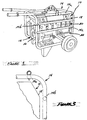
- the generator 12 includes a frame 14 for supporting an internal combustion engine 16.
- An electric generator (hidden from view) is coupled to an output shaft of the engine 16.
- the control panel 10 includes a plurality of switches and electrical receptacles which are logically and ergonomically arranged to provide significantly increased ease of use of the generator 12. To this end, the control panel 10 is divided into a plurality of distinct regions or "zones" 18, 20 and 22.
- the frame 14 further includes tubular frame members 14a, 14b and 14c which are disposed generally parallel to one another, and which further help to demarcate the three distinct zones 18, 20 and 22 of the control panel 10 and to protect the components on the control panel from damage due to accidental contact with other tools or objects.
- Each zone 18, 20 and 22 comprises a horizontally laid out, generally rectangular area, and each of the zones are arranged parallel to one another.
- the uppermost zone 18 includes an ON/OFF engine switch 24 at one longitudinal end of the zone 18 and a main circuit breaker switch 26 at the opposite longitudinal end of the zone.
- the switches 24 and 26 are further separated by an indicia member or area 28 in which a company name or other indicia identifying the manufacturer of the generator 12 may be included.
- the first zone 18 of the control panel 10 is further formed so as to be inclined slightly relative to the other zones 20 and 22, as indicated in Figure 3, to present slightly easier access to the switches 24 and 26.
- Each of the switches 24 and 26 are illustrated as rocker style switches, but it will be appreciated that push button switches, slide style switches, toggle style switches or virtually any other form of switch could easily be incorporated in lieu of rocker style switches.
- the second zone 20 is also configured as an elongated, rectangular region.
- the second zone 20 includes a plurality of electrical receptacles or outlets 30, 32, 34 and 36 arranged within a first subregion 20a.
- Outlets 30 and 36 comprise conventional twist lock receptacles for use with mating male twist lock electrical plugs.
- Outlets 30 and 36 preferably are capable of supplying 20 to 30 amps of current.
- Electrical outlets 32 and 34 are ground fault interrupter (GFI) electrical outlets which each supply 120VAC and preferably up to 20 amps of current or more.
- GFI ground fault interrupter
- Thermal circuit breakers 38, 40, 42 and 44 are each associated with a respective one of the outlets 30-36.
- each thermal breaker 38-44 is disposed closely adjacent the electrical receptacle 30-36 with which it is associated.
- thermal breaker 38 is associated with outlet 30
- thermal breaker 40 is associated with outlet 32
- thermal breaker 42 is associated with outlet 34
- thermal breaker 44 is associated with outlet 36.
- a voltage selector switch 46 is disposed within a second subregion 20b of region 20 while a 120/240VAC electrical outlet 48 is disposed within a third subzone 20c of zone 20.
- the voltage selector switch 46 in one preferred from comprises a rocker style switch which is laid out horizontally. Indicia 46a to the left of switch 46 indicates to the user that depressing the left side of the switch selects the outlets 30-36 for maximum 120VAC power. Pressing the right side of switch 46 selects outlet 48 for 240VAC operation.
- the placement of the switch 46 inbetween the group of outlets 30-36 and outlet 48, along with its horizontal positioning, helps to ensure that the operator realizes which electrical receptacles are being selected for use.
- the 120/240VAC electrical outlet 48 is disposed at the longitudinally opposite end of the zone 20b from the 120VAC electrical outlets 30-36. This further helps to reduce the possibility that the operator may inadvertently attempt to plug a 120VAC electrical plug into the 120/240VAC outlet 48.
- the third zone 22 includes an "Idle Control" on/off switch 52.
- This switch is typically used less frequently than switches 24, 26 or 46, and is therefore disposed at the lowermost area of the control panel 10. Switches 24 and 26, being much more commonly used, are disposed in the first zone 18.
- the auto throttle on/off switch 52 is used to choose whether or not the gas engine 16 will run at one constant speed, or throttle up and throttle down automatically depending on current draw on the generator 12.
- control panel 10 of the present invention provides the switches, electrical outlets and circuit breakers typically used with a portable electric generator in a highly logically organized arrangement.
- the arrangement of the control panel 10 into distinct zones further significantly reduces the possibility of the user unintentionally attempting to engage the wrong electrical outlet with a given electrical plug.
- the placement of the various control switches also significantly improves the convenience of use of the control panel 10 by locating those switches which are accessed most frequently at the upper area of the control panel, while switches which are accessed less frequently are disposed at lower locations on the control panel.
- the generally central placement of the voltage selector switch 46 further helps to ensure that the operator will not accidentally select the wrong electrical outlet for use.
Landscapes
- Engineering & Computer Science (AREA)
- Chemical & Material Sciences (AREA)
- Combustion & Propulsion (AREA)
- Mechanical Engineering (AREA)
- General Engineering & Computer Science (AREA)
- Air Conditioning Control Device (AREA)
- Switch Cases, Indication, And Locking (AREA)
- Breakers (AREA)
Applications Claiming Priority (2)
| Application Number | Priority Date | Filing Date | Title |
|---|---|---|---|
| US873468 | 2001-06-04 | ||
| US09/873,468 US6801425B2 (en) | 2001-06-04 | 2001-06-04 | Ergonomic control panel for a portable electric generator |
Publications (3)
| Publication Number | Publication Date |
|---|---|
| EP1265340A2 true EP1265340A2 (de) | 2002-12-11 |
| EP1265340A3 EP1265340A3 (de) | 2003-09-24 |
| EP1265340B1 EP1265340B1 (de) | 2014-09-17 |
Family
ID=25361692
Family Applications (1)
| Application Number | Title | Priority Date | Filing Date |
|---|---|---|---|
| EP02011413.8A Expired - Lifetime EP1265340B1 (de) | 2001-06-04 | 2002-05-24 | Ergonomisches Schaltbrett für einen tragbaren Elektrogenerator |
Country Status (2)
| Country | Link |
|---|---|
| US (2) | US6801425B2 (de) |
| EP (1) | EP1265340B1 (de) |
Cited By (6)
| Publication number | Priority date | Publication date | Assignee | Title |
|---|---|---|---|---|
| WO2005005225A1 (ja) * | 2003-07-10 | 2005-01-20 | Honda Motor Co., Ltd. | エンジン駆動式作業機 |
| FR2877782A1 (fr) * | 2004-11-10 | 2006-05-12 | Guernet Sarl | Dispositif pour generer simultanement ou alternativement un courant electrique et un fluide comprime |
| JP2007218227A (ja) * | 2006-02-20 | 2007-08-30 | Kokusan Denki Co Ltd | エンジン発電機 |
| RU2347132C1 (ru) * | 2006-07-19 | 2009-02-20 | Хонда Мотор Ко., Лтд | Система рабочего устройства с приводом от двигателя |
| CN102009678A (zh) * | 2009-09-04 | 2011-04-13 | 本田技研工业株式会社 | 工作机 |
| WO2010030903A3 (en) * | 2008-09-11 | 2011-08-25 | Champion Power Equipment, Inc. | A portable generator having a detachable panel |
Families Citing this family (21)
| Publication number | Priority date | Publication date | Assignee | Title |
|---|---|---|---|---|
| US8319357B2 (en) * | 2002-06-06 | 2012-11-27 | Black & Decker Inc. | Starter system for portable internal combustion engine electric generators using a portable universal battery pack |
| US7989969B2 (en) | 2002-06-06 | 2011-08-02 | Black & Decker Inc. | Universal power tool battery pack coupled to a portable internal combustion engine |
| JP4243151B2 (ja) * | 2003-07-10 | 2009-03-25 | 本田技研工業株式会社 | エンジン駆動式発電機 |
| JP4255437B2 (ja) * | 2004-12-07 | 2009-04-15 | ヤマハモーターパワープロダクツ株式会社 | エンジン式発電機 |
| USD546770S1 (en) * | 2005-08-30 | 2007-07-17 | Ingersoll-Rand Company | Mobile generator control panel |
| US7499263B2 (en) * | 2005-08-30 | 2009-03-03 | Doosan Infracore Co., Ltd. | Mobile power source cable connection system and method |
| US20070085692A1 (en) * | 2005-10-19 | 2007-04-19 | Black & Decker Inc. | Carbon monoxide detector on a gas powered generator |
| US8584564B2 (en) * | 2006-04-21 | 2013-11-19 | Black & Decker Inc. | Table saw |
| US7471000B1 (en) * | 2006-04-25 | 2008-12-30 | Ruiz Rafael J | Portable battery charger powered by internal combustion engine |
| US7667341B2 (en) * | 2006-09-29 | 2010-02-23 | Milwaukee Electric Tool Corporation | Power-generating apparatus, such as a generator |
| USD597944S1 (en) | 2008-10-22 | 2009-08-11 | John Takamura | Portable electricity generator chassis |
| USD597945S1 (en) | 2008-10-22 | 2009-08-11 | John Takamura | Control panel for a portable generator |
| US20100117386A1 (en) * | 2008-11-07 | 2010-05-13 | Ying Xi-Ren | Crane lift kit assembly |
| US8935995B1 (en) | 2009-01-30 | 2015-01-20 | Bobby L. Hawkins | Wheeled, manually moveable electric generator |
| US8546963B2 (en) * | 2009-04-21 | 2013-10-01 | Safecross Solutions, Llc | Generator frame with grappling attachment feature and theft deterring weight receptacle |
| US8138430B1 (en) | 2009-06-27 | 2012-03-20 | Jose Ucero | Window power distribution panel for exterior generator |
| JP5514644B2 (ja) * | 2010-06-22 | 2014-06-04 | 本田技研工業株式会社 | 作業機のハンドル装置 |
| US9099846B2 (en) | 2012-07-20 | 2015-08-04 | Assembled Products, A Unit Of Jason Incorporated | Plug and play control panel module with integrally socketed circuit board |
| WO2018126121A1 (en) * | 2016-12-30 | 2018-07-05 | The Esab Group Inc. | Smart power monitoring for a welding and cutting apparatus |
| CA3027957A1 (en) * | 2017-12-20 | 2019-06-20 | Tti (Macao Commercial Offshore) Limited | Portable power generator with power monitor and control |
| US11201455B1 (en) * | 2020-06-10 | 2021-12-14 | Richard Lee | Temporary electrical panel |
Citations (2)
| Publication number | Priority date | Publication date | Assignee | Title |
|---|---|---|---|---|
| US4907546A (en) | 1987-12-02 | 1990-03-13 | Kubota Ltd. | Air-cooled type cooling system for engine working machine assembly |
| US6331740B1 (en) | 1999-05-21 | 2001-12-18 | Honda Giken Kogyo Kabushiki Kaisha | Engine generator unit |
Family Cites Families (35)
| Publication number | Priority date | Publication date | Assignee | Title |
|---|---|---|---|---|
| US2361768A (en) | 1943-05-08 | 1944-10-31 | Jack & Heintz Inc | Self-contained energizer |
| US2898542A (en) * | 1957-02-18 | 1959-08-04 | George J Wasko | Portable generator unit |
| US2937832A (en) | 1958-08-22 | 1960-05-24 | Kenneth L Treiber | Carrying device |
| US3194525A (en) | 1964-02-07 | 1965-07-13 | James E Webb | Supporting and protecting device |
| US4173951A (en) | 1977-06-09 | 1979-11-13 | Masamitsu Ishihara | Power plant for simultaneously generating electric power and pneumatic pressure |
| USD275946S (en) * | 1982-01-27 | 1984-10-16 | Yamaha Hatsudoki Kabushiki Kaisha | Electric generator |
| USD277954S (en) * | 1982-04-13 | 1985-03-12 | Honda Giken Kogyo Kabushiki Kaisha | Engine generator |
| USD276515S (en) * | 1982-04-16 | 1984-11-27 | Honda Giken Kogyo Kabushiki Kaisha | Power generator |
| US4526228A (en) * | 1983-01-18 | 1985-07-02 | Wynn Samuel R | Apparatus for operating a gas and oil producing well |
| DE3410976A1 (de) * | 1983-03-18 | 1984-10-04 | Honda Giken Kogyo K.K., Tokio/Tokyo | Vollstaendig abgekapselter, tragbarer generator |
| JPH0128270Y2 (de) * | 1984-10-09 | 1989-08-29 | ||
| DE3528148A1 (de) | 1985-08-06 | 1987-02-19 | Hermann Silbernagel Fa | Sicherheitseinrichtung fuer einen mobilen und/oder stationaeren ersatzstromerzeuger |
| JPS6387152A (ja) * | 1986-09-29 | 1988-04-18 | Kawasaki Heavy Ind Ltd | エンジン付機器の制御表示装置 |
| US4729353A (en) | 1986-12-29 | 1988-03-08 | Engineered Air Systems, Inc. | Fuel container support system for a combustion engine |
| US5353762A (en) * | 1993-05-10 | 1994-10-11 | Briggs & Stratton Corporation | Modular automatic speed changing system |
| DE4414067A1 (de) | 1994-04-23 | 1995-10-26 | Lai Xiao Wei | Der Mini-Mehrzweckstromerzeuger (mit Benzinmotor oder Dieselmotor getrieben) mit der gleichen Abgabeleistung für Autopannenhilfe und anderen Gebrauch |
| US5697249A (en) | 1994-09-09 | 1997-12-16 | Kawasaki Jukogyo Kabushiki Kaisha | Portable drive unit |
| US5929611A (en) * | 1994-09-14 | 1999-07-27 | Coleman Powermate, Inc. | Light weight rotor and stator with multiple coil windings in thermal contact |
| US5574622A (en) * | 1995-05-22 | 1996-11-12 | Brown; Julius | Power truck |
| US5734148A (en) * | 1995-09-11 | 1998-03-31 | Miller Electric Manufacturing Co. | Retention means for side panels for welding machine |
| US5765995A (en) * | 1995-10-16 | 1998-06-16 | Diesel Power Supply Co. | Automated engine-powered pump control system |
| JPH09151745A (ja) * | 1995-12-01 | 1997-06-10 | Sawafuji Electric Co Ltd | 可搬式エンジン発電機 |
| US5726503A (en) * | 1996-02-29 | 1998-03-10 | Wacker Corporation | Low speed idle actuator and method of use thereof |
| JPH1089083A (ja) | 1996-09-10 | 1998-04-07 | Sawafuji Electric Co Ltd | エンジン発電機 |
| JP3418079B2 (ja) | 1997-01-24 | 2003-06-16 | 澤藤電機株式会社 | 発動発電機 |
| JP3815703B2 (ja) * | 1997-07-24 | 2006-08-30 | 本田技研工業株式会社 | エンジン発電機 |
| JP3954700B2 (ja) * | 1997-09-09 | 2007-08-08 | 澤藤電機株式会社 | 発動発電機 |
| JP2000042300A (ja) * | 1998-05-22 | 2000-02-15 | Shinsei Shoji Kk | 野外洗濯車 |
| JP2000041347A (ja) * | 1998-07-21 | 2000-02-08 | Sawafuji Electric Co Ltd | 非常用電源装置 |
| US6084313A (en) | 1998-08-13 | 2000-07-04 | Coleman Powermate, Inc. | Generator system with vertically shafted engine |
| EP1054147B1 (de) * | 1999-05-20 | 2005-07-27 | Honda Giken Kogyo Kabushiki Kaisha | Brennkraftmaschine-Generator-Baueinheit |
| US6119636A (en) * | 1999-06-11 | 2000-09-19 | Fan; Guo Xiang | Portable generator |
| JP2001123899A (ja) * | 1999-10-21 | 2001-05-08 | Honda Motor Co Ltd | エンジン用エアクリーナ |
| US6541718B2 (en) * | 2001-03-07 | 2003-04-01 | Devilbiss Air Power Company | Full power switch assembly for portable generators |
| US6476509B1 (en) * | 2001-04-19 | 2002-11-05 | Unit Parts Company | Mobile AC power system |
-
2001
- 2001-06-04 US US09/873,468 patent/US6801425B2/en not_active Expired - Fee Related
-
2002
- 2002-05-24 EP EP02011413.8A patent/EP1265340B1/de not_active Expired - Lifetime
-
2004
- 2004-08-09 US US10/914,683 patent/US7224578B2/en not_active Expired - Fee Related
Patent Citations (2)
| Publication number | Priority date | Publication date | Assignee | Title |
|---|---|---|---|---|
| US4907546A (en) | 1987-12-02 | 1990-03-13 | Kubota Ltd. | Air-cooled type cooling system for engine working machine assembly |
| US6331740B1 (en) | 1999-05-21 | 2001-12-18 | Honda Giken Kogyo Kabushiki Kaisha | Engine generator unit |
Cited By (10)
| Publication number | Priority date | Publication date | Assignee | Title |
|---|---|---|---|---|
| WO2005005225A1 (ja) * | 2003-07-10 | 2005-01-20 | Honda Motor Co., Ltd. | エンジン駆動式作業機 |
| AU2004255629B2 (en) * | 2003-07-10 | 2008-05-29 | Honda Motor Co., Ltd. | Engine-driven working machine |
| CN100450846C (zh) * | 2003-07-10 | 2009-01-14 | 本田技研工业株式会社 | 发动机驱动式工作机 |
| US7597340B2 (en) | 2003-07-10 | 2009-10-06 | Honda Motor Co., Ltd. | Engine-driven work machine |
| FR2877782A1 (fr) * | 2004-11-10 | 2006-05-12 | Guernet Sarl | Dispositif pour generer simultanement ou alternativement un courant electrique et un fluide comprime |
| JP2007218227A (ja) * | 2006-02-20 | 2007-08-30 | Kokusan Denki Co Ltd | エンジン発電機 |
| RU2347132C1 (ru) * | 2006-07-19 | 2009-02-20 | Хонда Мотор Ко., Лтд | Система рабочего устройства с приводом от двигателя |
| WO2010030903A3 (en) * | 2008-09-11 | 2011-08-25 | Champion Power Equipment, Inc. | A portable generator having a detachable panel |
| CN102009678A (zh) * | 2009-09-04 | 2011-04-13 | 本田技研工业株式会社 | 工作机 |
| CN102009678B (zh) * | 2009-09-04 | 2013-02-13 | 本田技研工业株式会社 | 工作机 |
Also Published As
| Publication number | Publication date |
|---|---|
| US6801425B2 (en) | 2004-10-05 |
| US7224578B2 (en) | 2007-05-29 |
| EP1265340B1 (de) | 2014-09-17 |
| US20050018373A1 (en) | 2005-01-27 |
| US20020180407A1 (en) | 2002-12-05 |
| EP1265340A3 (de) | 2003-09-24 |
Similar Documents
| Publication | Publication Date | Title |
|---|---|---|
| US6801425B2 (en) | Ergonomic control panel for a portable electric generator | |
| HK3489A (en) | Unitary electrical plug with multiple inlets and voltage converter | |
| US8929046B2 (en) | DC branch circuit protecting device | |
| CN201903022U (zh) | 组合电气装置 | |
| US20060126243A1 (en) | Power strip with 12 volt outlet | |
| JP2005522007A (ja) | 低電圧配電回路 | |
| US20140312695A1 (en) | Switch-Type Interlock Arrangement For Controlling The Neutral Output Of A Portable Generator | |
| US20060250759A1 (en) | Do-it-yourself system for portable generator | |
| US10389205B2 (en) | Motor programming tool | |
| US6310291B1 (en) | Utility lock-out apparatus | |
| US6011328A (en) | Electric power lockout apparatus | |
| US6913467B2 (en) | Multiple socket having rotatable socket units | |
| US20050007070A1 (en) | Personal power recharging organizer | |
| GB2355424A (en) | Improvement construction of hand tool set | |
| US20050012401A1 (en) | Switched outlet module and method therefor | |
| US8605395B1 (en) | Dual plug adapter and household high current apparatus | |
| US12486986B2 (en) | Portable heater with interchangeable battery | |
| GB2410624A (en) | Multi-outlet extension lead | |
| JP2020017533A (ja) | プラグのアタッチメント | |
| EP0952638A1 (de) | Zweipolige elektrische Stecker mit Schalter | |
| JP6878112B2 (ja) | 配線用遮断器 | |
| US6247936B1 (en) | Electrical distribution system with fuse selectable circuits | |
| EP1054482A2 (de) | Elektrische Steckdosenleiste | |
| KR101917212B1 (ko) | 유도전동기 결선 단자대 | |
| CN2909602Y (zh) | 多功能电源插线板 |
Legal Events
| Date | Code | Title | Description |
|---|---|---|---|
| PUAI | Public reference made under article 153(3) epc to a published international application that has entered the european phase |
Free format text: ORIGINAL CODE: 0009012 |
|
| AK | Designated contracting states |
Kind code of ref document: A2 Designated state(s): AT BE CH CY DE DK ES FI FR GB GR IE IT LI LU MC NL PT SE TR |
|
| AX | Request for extension of the european patent |
Free format text: AL;LT;LV;MK;RO;SI |
|
| PUAL | Search report despatched |
Free format text: ORIGINAL CODE: 0009013 |
|
| AK | Designated contracting states |
Kind code of ref document: A3 Designated state(s): AT BE CH CY DE DK ES FI FR GB GR IE IT LI LU MC NL PT SE TR |
|
| AX | Request for extension of the european patent |
Extension state: AL LT LV MK RO SI |
|
| RIC1 | Information provided on ipc code assigned before grant |
Ipc: 7F 02B 63/04 B Ipc: 7H 02K 5/22 A |
|
| 17P | Request for examination filed |
Effective date: 20031013 |
|
| AKX | Designation fees paid |
Designated state(s): AT BE CH CY DE DK ES FI FR GB GR IE IT LI LU MC NL PT SE TR |
|
| 17Q | First examination report despatched |
Effective date: 20120228 |
|
| GRAP | Despatch of communication of intention to grant a patent |
Free format text: ORIGINAL CODE: EPIDOSNIGR1 |
|
| INTG | Intention to grant announced |
Effective date: 20140417 |
|
| GRAS | Grant fee paid |
Free format text: ORIGINAL CODE: EPIDOSNIGR3 |
|
| GRAA | (expected) grant |
Free format text: ORIGINAL CODE: 0009210 |
|
| AK | Designated contracting states |
Kind code of ref document: B1 Designated state(s): AT BE CH CY DE DK ES FI FR GB GR IE IT LI LU MC NL PT SE TR |
|
| REG | Reference to a national code |
Ref country code: GB Ref legal event code: FG4D |
|
| REG | Reference to a national code |
Ref country code: CH Ref legal event code: EP |
|
| REG | Reference to a national code |
Ref country code: IE Ref legal event code: FG4D |
|
| REG | Reference to a national code |
Ref country code: AT Ref legal event code: REF Ref document number: 688076 Country of ref document: AT Kind code of ref document: T Effective date: 20141015 |
|
| REG | Reference to a national code |
Ref country code: DE Ref legal event code: R096 Ref document number: 60246633 Country of ref document: DE Effective date: 20141023 |
|
| PG25 | Lapsed in a contracting state [announced via postgrant information from national office to epo] |
Ref country code: SE Free format text: LAPSE BECAUSE OF FAILURE TO SUBMIT A TRANSLATION OF THE DESCRIPTION OR TO PAY THE FEE WITHIN THE PRESCRIBED TIME-LIMIT Effective date: 20140917 Ref country code: FI Free format text: LAPSE BECAUSE OF FAILURE TO SUBMIT A TRANSLATION OF THE DESCRIPTION OR TO PAY THE FEE WITHIN THE PRESCRIBED TIME-LIMIT Effective date: 20140917 Ref country code: GR Free format text: LAPSE BECAUSE OF FAILURE TO SUBMIT A TRANSLATION OF THE DESCRIPTION OR TO PAY THE FEE WITHIN THE PRESCRIBED TIME-LIMIT Effective date: 20141218 |
|
| REG | Reference to a national code |
Ref country code: NL Ref legal event code: VDEP Effective date: 20140917 |
|
| PG25 | Lapsed in a contracting state [announced via postgrant information from national office to epo] |
Ref country code: CY Free format text: LAPSE BECAUSE OF FAILURE TO SUBMIT A TRANSLATION OF THE DESCRIPTION OR TO PAY THE FEE WITHIN THE PRESCRIBED TIME-LIMIT Effective date: 20140917 |
|
| REG | Reference to a national code |
Ref country code: AT Ref legal event code: MK05 Ref document number: 688076 Country of ref document: AT Kind code of ref document: T Effective date: 20140917 |
|
| PG25 | Lapsed in a contracting state [announced via postgrant information from national office to epo] |
Ref country code: NL Free format text: LAPSE BECAUSE OF FAILURE TO SUBMIT A TRANSLATION OF THE DESCRIPTION OR TO PAY THE FEE WITHIN THE PRESCRIBED TIME-LIMIT Effective date: 20140917 |
|
| PG25 | Lapsed in a contracting state [announced via postgrant information from national office to epo] |
Ref country code: PT Free format text: LAPSE BECAUSE OF FAILURE TO SUBMIT A TRANSLATION OF THE DESCRIPTION OR TO PAY THE FEE WITHIN THE PRESCRIBED TIME-LIMIT Effective date: 20150119 Ref country code: ES Free format text: LAPSE BECAUSE OF FAILURE TO SUBMIT A TRANSLATION OF THE DESCRIPTION OR TO PAY THE FEE WITHIN THE PRESCRIBED TIME-LIMIT Effective date: 20140917 |
|
| PG25 | Lapsed in a contracting state [announced via postgrant information from national office to epo] |
Ref country code: AT Free format text: LAPSE BECAUSE OF FAILURE TO SUBMIT A TRANSLATION OF THE DESCRIPTION OR TO PAY THE FEE WITHIN THE PRESCRIBED TIME-LIMIT Effective date: 20140917 |
|
| REG | Reference to a national code |
Ref country code: DE Ref legal event code: R097 Ref document number: 60246633 Country of ref document: DE |
|
| PLBE | No opposition filed within time limit |
Free format text: ORIGINAL CODE: 0009261 |
|
| STAA | Information on the status of an ep patent application or granted ep patent |
Free format text: STATUS: NO OPPOSITION FILED WITHIN TIME LIMIT |
|
| PG25 | Lapsed in a contracting state [announced via postgrant information from national office to epo] |
Ref country code: DK Free format text: LAPSE BECAUSE OF FAILURE TO SUBMIT A TRANSLATION OF THE DESCRIPTION OR TO PAY THE FEE WITHIN THE PRESCRIBED TIME-LIMIT Effective date: 20140917 |
|
| 26N | No opposition filed |
Effective date: 20150618 |
|
| PG25 | Lapsed in a contracting state [announced via postgrant information from national office to epo] |
Ref country code: IT Free format text: LAPSE BECAUSE OF FAILURE TO SUBMIT A TRANSLATION OF THE DESCRIPTION OR TO PAY THE FEE WITHIN THE PRESCRIBED TIME-LIMIT Effective date: 20140917 |
|
| REG | Reference to a national code |
Ref country code: CH Ref legal event code: PL |
|
| PG25 | Lapsed in a contracting state [announced via postgrant information from national office to epo] |
Ref country code: CH Free format text: LAPSE BECAUSE OF NON-PAYMENT OF DUE FEES Effective date: 20150531 Ref country code: MC Free format text: LAPSE BECAUSE OF FAILURE TO SUBMIT A TRANSLATION OF THE DESCRIPTION OR TO PAY THE FEE WITHIN THE PRESCRIBED TIME-LIMIT Effective date: 20140917 Ref country code: LI Free format text: LAPSE BECAUSE OF NON-PAYMENT OF DUE FEES Effective date: 20150531 Ref country code: LU Free format text: LAPSE BECAUSE OF FAILURE TO SUBMIT A TRANSLATION OF THE DESCRIPTION OR TO PAY THE FEE WITHIN THE PRESCRIBED TIME-LIMIT Effective date: 20150524 |
|
| REG | Reference to a national code |
Ref country code: IE Ref legal event code: MM4A |
|
| REG | Reference to a national code |
Ref country code: FR Ref legal event code: ST Effective date: 20160129 |
|
| PG25 | Lapsed in a contracting state [announced via postgrant information from national office to epo] |
Ref country code: IE Free format text: LAPSE BECAUSE OF NON-PAYMENT OF DUE FEES Effective date: 20150524 |
|
| PG25 | Lapsed in a contracting state [announced via postgrant information from national office to epo] |
Ref country code: FR Free format text: LAPSE BECAUSE OF NON-PAYMENT OF DUE FEES Effective date: 20150601 |
|
| PGFP | Annual fee paid to national office [announced via postgrant information from national office to epo] |
Ref country code: GB Payment date: 20160518 Year of fee payment: 15 Ref country code: DE Payment date: 20160518 Year of fee payment: 15 |
|
| PG25 | Lapsed in a contracting state [announced via postgrant information from national office to epo] |
Ref country code: TR Free format text: LAPSE BECAUSE OF FAILURE TO SUBMIT A TRANSLATION OF THE DESCRIPTION OR TO PAY THE FEE WITHIN THE PRESCRIBED TIME-LIMIT Effective date: 20140917 |
|
| PG25 | Lapsed in a contracting state [announced via postgrant information from national office to epo] |
Ref country code: BE Free format text: LAPSE BECAUSE OF FAILURE TO SUBMIT A TRANSLATION OF THE DESCRIPTION OR TO PAY THE FEE WITHIN THE PRESCRIBED TIME-LIMIT Effective date: 20140917 |
|
| REG | Reference to a national code |
Ref country code: DE Ref legal event code: R119 Ref document number: 60246633 Country of ref document: DE |
|
| GBPC | Gb: european patent ceased through non-payment of renewal fee |
Effective date: 20170524 |
|
| PG25 | Lapsed in a contracting state [announced via postgrant information from national office to epo] |
Ref country code: DE Free format text: LAPSE BECAUSE OF NON-PAYMENT OF DUE FEES Effective date: 20171201 Ref country code: GB Free format text: LAPSE BECAUSE OF NON-PAYMENT OF DUE FEES Effective date: 20170524 |