US4729353A - Fuel container support system for a combustion engine - Google Patents
Fuel container support system for a combustion engine Download PDFInfo
- Publication number
- US4729353A US4729353A US06/947,279 US94727986A US4729353A US 4729353 A US4729353 A US 4729353A US 94727986 A US94727986 A US 94727986A US 4729353 A US4729353 A US 4729353A
- Authority
- US
- United States
- Prior art keywords
- fuel
- container
- combustion engine
- support system
- engine
- Prior art date
- Legal status (The legal status is an assumption and is not a legal conclusion. Google has not performed a legal analysis and makes no representation as to the accuracy of the status listed.)
- Expired - Fee Related
Links
Images
Classifications
-
- F—MECHANICAL ENGINEERING; LIGHTING; HEATING; WEAPONS; BLASTING
- F02—COMBUSTION ENGINES; HOT-GAS OR COMBUSTION-PRODUCT ENGINE PLANTS
- F02B—INTERNAL-COMBUSTION PISTON ENGINES; COMBUSTION ENGINES IN GENERAL
- F02B63/00—Adaptations of engines for driving pumps, hand-held tools or electric generators; Portable combinations of engines with engine-driven devices
- F02B63/04—Adaptations of engines for driving pumps, hand-held tools or electric generators; Portable combinations of engines with engine-driven devices for electric generators
-
- F—MECHANICAL ENGINEERING; LIGHTING; HEATING; WEAPONS; BLASTING
- F16—ENGINEERING ELEMENTS AND UNITS; GENERAL MEASURES FOR PRODUCING AND MAINTAINING EFFECTIVE FUNCTIONING OF MACHINES OR INSTALLATIONS; THERMAL INSULATION IN GENERAL
- F16M—FRAMES, CASINGS OR BEDS OF ENGINES, MACHINES OR APPARATUS, NOT SPECIFIC TO ENGINES, MACHINES OR APPARATUS PROVIDED FOR ELSEWHERE; STANDS; SUPPORTS
- F16M3/00—Portable or wheeled frames or beds, e.g. for emergency power-supply aggregates, compressor sets
-
- F—MECHANICAL ENGINEERING; LIGHTING; HEATING; WEAPONS; BLASTING
- F02—COMBUSTION ENGINES; HOT-GAS OR COMBUSTION-PRODUCT ENGINE PLANTS
- F02B—INTERNAL-COMBUSTION PISTON ENGINES; COMBUSTION ENGINES IN GENERAL
- F02B63/00—Adaptations of engines for driving pumps, hand-held tools or electric generators; Portable combinations of engines with engine-driven devices
- F02B63/04—Adaptations of engines for driving pumps, hand-held tools or electric generators; Portable combinations of engines with engine-driven devices for electric generators
- F02B63/044—Adaptations of engines for driving pumps, hand-held tools or electric generators; Portable combinations of engines with engine-driven devices for electric generators the engine-generator unit being placed on a frame or in an housing
- F02B2063/045—Frames for generator-engine sets
-
- F—MECHANICAL ENGINEERING; LIGHTING; HEATING; WEAPONS; BLASTING
- F02—COMBUSTION ENGINES; HOT-GAS OR COMBUSTION-PRODUCT ENGINE PLANTS
- F02B—INTERNAL-COMBUSTION PISTON ENGINES; COMBUSTION ENGINES IN GENERAL
- F02B63/00—Adaptations of engines for driving pumps, hand-held tools or electric generators; Portable combinations of engines with engine-driven devices
- F02B63/04—Adaptations of engines for driving pumps, hand-held tools or electric generators; Portable combinations of engines with engine-driven devices for electric generators
- F02B63/044—Adaptations of engines for driving pumps, hand-held tools or electric generators; Portable combinations of engines with engine-driven devices for electric generators the engine-generator unit being placed on a frame or in an housing
- F02B63/048—Portable engine-generator combinations
Definitions
- the present invention relates to combustion engines and more particularly to an improved fuel container support system for a combustion engine.
- Small liquid fuel burning combustion engines utilized in both military and commercial situations for furnishing power to various units such as (but not limited to) portable heaters, portable air conditioners, portable kitchens and portable pumps, have required usage of portable fuel containers to store liquid fuels such as gasoline or diesel oil which serve to fuel the combustion engines.
- these containers often have been stored with the same portable structure which serves to house the combustion engine or, if stored separately, have fed fuel to the engine from a position immediately above the engine to utilize gravity flow.
- the present invention recognizes that these past practices have presented safety hazards, with small quantities of fuel from the container often spilling over on hot combustion engine parts enhancing the risks of unconfined and uncontrollable fires.
- the present invention provides a unique fuel container support system, that is economical in manufacture, assembly and usage, which is compact for transport and storage with surrounding combustion engine support structure, which can be readily moved to a preselected, safe supportive position by a simple manual manipulation when a fuel container is required to support combustion engine operations and can be returned by an equally simple manual manipulation to the initial compact transport and storage position when combustion engine operations cease.
- the present invention provides an improved fuel container support system for a combustion engine comprising: a combustion engine; frame means adjacent the combustion engine; a shelf member supportively mounted on the frame means in a first position adjacent the engine; and, means to permit movement of the shelf member relative the frame means to a second position removed from the combustion engine to support a fuel container thereon to supply fuel to the combustion engine.
- the present invention provides a unique pumping arrangement for moving fuel from the container to the combustion engine.
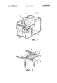
- FIG. 1 is a perspective view of the novel fuel container support system including the fuel container in association with a combustion engine and surrounding combustion engine support structure, some of the units driven by the combustion engine being shown in block form; and,
- FIG. 2 is a partial, broken away perspective view of the novel shelf member in cantilevered position to receive a fuel container.
- combustion engine 2 is shown mounted in a comparatively light weight, generally rectangular tubular skid frame structure 3.
- This skid frame structure also can serve to house other units such as a heater, an air conditioner, a stove or a pump, schematic block form being used in the drawing for these units.
- the combustion engine 3 as disclosed is a typical gasoline fueled engine but it is to be understood that other types of engines requiring other liquid fuels can be utilized with the present invention.
- shelf 7 mounted on spaced opposed tubular members of frame 3 is a pair of spaced open-ended tubular rail members 4 which serve to receive a pair of appropriately spaced slide bars 6 mounted on the moveable shelf member generally designated by reference numeral 7.
- Shelf 7 includes a vertical end plate 8 to which the corresponding spaced ends of slide bars 6 are normally mounted.
- the other or opposite ends of slide bars 6 telescopically engage in tubular rail members 4 fixed to frame 3 for sliding telescopic movement therein to move shelf member 7 from a first position above engine 2 to a cantilevered safer position away from the main body of frame 3 and engine 2 housed therein.
- End plate 8 has a container support bracket broadly designated by reference numeral 9 mounted thereto between slide bars 8.
- Support bracket 9 includes a pair of spaced Z-straps 11, one of the corresponding ends of which is mounted to end plate 8 and the opposite corresponding ends having the ends of a stop bar 12 fixed thereto to extend therebetween.
- Bar 12 is positioned to abut against frame 3 when shelf member 7 is cantilevered to open position, thus limiting the shelf from further extension and disconnection in the event of conditions such as engine vibration.
- the spaced cantilivered Z-straps are provided with a right angle cradle strap 13 mounted at its opposite ends to points intermediate Z-straps 11 to extend therebetween.
- Right angle cradle strap 13 serves to receive a nesting bottom corner of a generally rectangular portable fuel container 14, the bottom corner of container 14 nesting at the apex of the right angle of cradle strap 13 with the longitudinal side of container 14 resting on the length of strap 13.
- containers could be utilized if desired, such containers being advantageously designed to nest at a corner with the shelf cradle and rest at an angle to the horizontal so that fuel concentrates by gravity during usage at the lowest container corner. Since most commercial and military portable containers are of the typical five gallon "GI" type, such a container is disclosed herein.
- GI five gallon
- FIG. 1 A fuel line 17 is provided having one end extending through vented cap 16 into portable fuel container 14.
- pump 18 can be a diaphragm type pump operative on the engine compression vacuum cycle of combustion engine 2.
- a suitable manually compressible pump 19 can be included in fuel line 17 to initiate fuel flow through line 17 to engine 2. It is to be understood that a suitable air filter 21 can be provided for the intake of engine 2 and a suitable liquid filter 22 can be provided in fuel line 17.
- engine driven diaphragm pump 18 takes over to assure a steady flow of fuel from shelf supported portable container 14 to the engine.
- portable container 14 is removed from shelf 7, shelf 7 is pushed manually inward until end plate 8 abuts frame 3 and the entire frame 3 and container 14 can be transported separately to another site.
Landscapes
- Engineering & Computer Science (AREA)
- General Engineering & Computer Science (AREA)
- Mechanical Engineering (AREA)
- Chemical & Material Sciences (AREA)
- Combustion & Propulsion (AREA)
- Cooling, Air Intake And Gas Exhaust, And Fuel Tank Arrangements In Propulsion Units (AREA)
Abstract
Description
Claims (7)
Priority Applications (1)
| Application Number | Priority Date | Filing Date | Title |
|---|---|---|---|
| US06/947,279 US4729353A (en) | 1986-12-29 | 1986-12-29 | Fuel container support system for a combustion engine |
Applications Claiming Priority (1)
| Application Number | Priority Date | Filing Date | Title |
|---|---|---|---|
| US06/947,279 US4729353A (en) | 1986-12-29 | 1986-12-29 | Fuel container support system for a combustion engine |
Publications (1)
| Publication Number | Publication Date |
|---|---|
| US4729353A true US4729353A (en) | 1988-03-08 |
Family
ID=25485880
Family Applications (1)
| Application Number | Title | Priority Date | Filing Date |
|---|---|---|---|
| US06/947,279 Expired - Fee Related US4729353A (en) | 1986-12-29 | 1986-12-29 | Fuel container support system for a combustion engine |
Country Status (1)
| Country | Link |
|---|---|
| US (1) | US4729353A (en) |
Cited By (7)
| Publication number | Priority date | Publication date | Assignee | Title |
|---|---|---|---|---|
| US5162662A (en) * | 1989-09-22 | 1992-11-10 | Yamaha Hatsudoki Kabushiki Kaisha | Compact power supply with gas engine |
| US5907970A (en) * | 1997-10-15 | 1999-06-01 | Havlovick; Bradley J. | Take-off power package system |
| US20030183180A1 (en) * | 2002-03-27 | 2003-10-02 | Masami Wada | Fluid supply mechanism for power generator |
| US6801425B2 (en) | 2001-06-04 | 2004-10-05 | Black & Decker Inc. | Ergonomic control panel for a portable electric generator |
| USD751037S1 (en) * | 2013-07-30 | 2016-03-08 | Ini Power Systems, Inc. | Gas adaptor for electric generator |
| USD777668S1 (en) * | 2015-03-09 | 2017-01-31 | Hsin-Yung Lin | Generator for oxyhydrogen gas |
| CN111433444A (en) * | 2017-12-11 | 2020-07-17 | 本田技研工业株式会社 | Engine device |
Citations (6)
| Publication number | Priority date | Publication date | Assignee | Title |
|---|---|---|---|---|
| US1751625A (en) * | 1926-03-25 | 1930-03-25 | Novo Engine Company | Internal-combustion engine |
| US2274644A (en) * | 1939-06-12 | 1942-03-03 | Thomas R Arden | Internal combustion engine and adjuncts therefor |
| US3170005A (en) * | 1963-01-30 | 1965-02-16 | Tillotson Mfg Co | Fuel feed system for internal combustion engines |
| US4117342A (en) * | 1977-01-13 | 1978-09-26 | Melley Energy Systems | Utility frame for mobile electric power generating systems |
| US4226214A (en) * | 1977-07-29 | 1980-10-07 | Fiat Auto S.P.A. | Apparatus for the combined production of electrical energy and heat |
| US4503812A (en) * | 1982-03-15 | 1985-03-12 | Hale Fire Pump Company | Starting system for a portable engine-pump unit |
-
1986
- 1986-12-29 US US06/947,279 patent/US4729353A/en not_active Expired - Fee Related
Patent Citations (6)
| Publication number | Priority date | Publication date | Assignee | Title |
|---|---|---|---|---|
| US1751625A (en) * | 1926-03-25 | 1930-03-25 | Novo Engine Company | Internal-combustion engine |
| US2274644A (en) * | 1939-06-12 | 1942-03-03 | Thomas R Arden | Internal combustion engine and adjuncts therefor |
| US3170005A (en) * | 1963-01-30 | 1965-02-16 | Tillotson Mfg Co | Fuel feed system for internal combustion engines |
| US4117342A (en) * | 1977-01-13 | 1978-09-26 | Melley Energy Systems | Utility frame for mobile electric power generating systems |
| US4226214A (en) * | 1977-07-29 | 1980-10-07 | Fiat Auto S.P.A. | Apparatus for the combined production of electrical energy and heat |
| US4503812A (en) * | 1982-03-15 | 1985-03-12 | Hale Fire Pump Company | Starting system for a portable engine-pump unit |
Cited By (11)
| Publication number | Priority date | Publication date | Assignee | Title |
|---|---|---|---|---|
| US5162662A (en) * | 1989-09-22 | 1992-11-10 | Yamaha Hatsudoki Kabushiki Kaisha | Compact power supply with gas engine |
| US5907970A (en) * | 1997-10-15 | 1999-06-01 | Havlovick; Bradley J. | Take-off power package system |
| US6801425B2 (en) | 2001-06-04 | 2004-10-05 | Black & Decker Inc. | Ergonomic control panel for a portable electric generator |
| US20050018373A1 (en) * | 2001-06-04 | 2005-01-27 | Buck John E. | Ergonomic control panel for a portable electric generator |
| US7224578B2 (en) * | 2001-06-04 | 2007-05-29 | Black & Decker Inc. | Ergonomic control panel for a portable electric generator |
| US20030183180A1 (en) * | 2002-03-27 | 2003-10-02 | Masami Wada | Fluid supply mechanism for power generator |
| US7073475B2 (en) * | 2002-03-27 | 2006-07-11 | Yamaha Hatsudoki Kabushiki Kaisha | Fluid supply mechanism for power generator |
| USD751037S1 (en) * | 2013-07-30 | 2016-03-08 | Ini Power Systems, Inc. | Gas adaptor for electric generator |
| USD777668S1 (en) * | 2015-03-09 | 2017-01-31 | Hsin-Yung Lin | Generator for oxyhydrogen gas |
| CN111433444A (en) * | 2017-12-11 | 2020-07-17 | 本田技研工业株式会社 | Engine device |
| CN111433444B (en) * | 2017-12-11 | 2021-09-03 | 本田技研工业株式会社 | Engine device |
Similar Documents
| Publication | Publication Date | Title |
|---|---|---|
| US4729353A (en) | Fuel container support system for a combustion engine | |
| US4003356A (en) | Vaporized fuel system for internal combustion engines | |
| US3884214A (en) | Charcoal starter and grill | |
| US5162662A (en) | Compact power supply with gas engine | |
| US5575195A (en) | Collapsible portable cooking unit | |
| US4954075A (en) | Lantern head for backpacker's stove | |
| US4503812A (en) | Starting system for a portable engine-pump unit | |
| US3699938A (en) | Gas expander | |
| US4157700A (en) | Pre-vaporization system | |
| CN206771475U (en) | A kind of lampblack absorber for being easy to gas-cooker to store | |
| US5337729A (en) | Portable heater for vehicle engines | |
| CN109864606A (en) | A kind of barbecue furnace body | |
| NO142794B (en) | ASYMMETRIC LIGHT SCREEN. | |
| US6227190B1 (en) | Fireplace fire starting device | |
| US2963254A (en) | Collapsible fuel barrel rack for trailers | |
| CN214700297U (en) | Electric heating deep sea sunken ship oil pumping device | |
| US1450870A (en) | Vapor stove | |
| US2998844A (en) | Vapor lock reduction device for automotive vehicles | |
| KR102101184B1 (en) | Vehicle water injection system | |
| CN2302419Y (en) | Portable range adapted for the use of many kinds of liquid and gas fuel | |
| US3609073A (en) | Oil burner apparatus | |
| CN200958848Y (en) | Gas heater | |
| CN214745943U (en) | Novel alcohol-based fuel stove fuel tank | |
| CN216281362U (en) | Domestic alcohol-free synthetic liquid fuel heating stove | |
| RU216618U1 (en) | CAMPING OVEN |
Legal Events
| Date | Code | Title | Description |
|---|---|---|---|
| AS | Assignment |
Owner name: ENGINEERED AIR SYSTEMS, INC., 1270 NORTH PRICE RD. Free format text: ASSIGNMENT OF ASSIGNORS INTEREST.;ASSIGNOR:STRENG, ROGER H.;REEL/FRAME:004671/0785 Effective date: 19861215 Owner name: ENGINEERED AIR SYSTEMS, INC.,MICHIGAN Free format text: ASSIGNMENT OF ASSIGNORS INTEREST;ASSIGNOR:STRENG, ROGER H.;REEL/FRAME:004671/0785 Effective date: 19861215 |
|
| AS | Assignment |
Owner name: FIRST WISCONSIN TRUST COMPANY, WISCONSIN Free format text: SECURITY AND LICENSE AGREEMENT;ASSIGNOR:ENGINEERED AIR SYSTEMS, INC.;REEL/FRAME:005046/0173 Effective date: 19880913 Owner name: FIRST WISCONSIN NATIONAL BANK OF MILWAUKEE, WISCON Free format text: SECURITY AND LICENSE AGREEMENT;ASSIGNOR:ENGINEERED AIR SYSTEMS, INC.;REEL/FRAME:005046/0173 Effective date: 19880913 |
|
| FEPP | Fee payment procedure |
Free format text: PAT HOLDER CLAIMS SMALL ENTITY STATUS - SMALL BUSINESS (ORIGINAL EVENT CODE: SM02); ENTITY STATUS OF PATENT OWNER: SMALL ENTITY |
|
| FPAY | Fee payment |
Year of fee payment: 4 |
|
| FPAY | Fee payment |
Year of fee payment: 8 |
|
| REMI | Maintenance fee reminder mailed | ||
| LAPS | Lapse for failure to pay maintenance fees | ||
| FP | Lapsed due to failure to pay maintenance fee |
Effective date: 20000308 |
|
| STCH | Information on status: patent discontinuation |
Free format text: PATENT EXPIRED DUE TO NONPAYMENT OF MAINTENANCE FEES UNDER 37 CFR 1.362 |