EP1264116B1 - Gelenk - Google Patents
Gelenk Download PDFInfo
- Publication number
- EP1264116B1 EP1264116B1 EP00990809A EP00990809A EP1264116B1 EP 1264116 B1 EP1264116 B1 EP 1264116B1 EP 00990809 A EP00990809 A EP 00990809A EP 00990809 A EP00990809 A EP 00990809A EP 1264116 B1 EP1264116 B1 EP 1264116B1
- Authority
- EP
- European Patent Office
- Prior art keywords
- bearing
- axis
- roller bearing
- joint according
- outer ring
- Prior art date
- Legal status (The legal status is an assumption and is not a legal conclusion. Google has not performed a legal analysis and makes no representation as to the accuracy of the status listed.)
- Expired - Lifetime
Links
- 238000005242 forging Methods 0.000 claims 1
- 238000000034 method Methods 0.000 claims 1
- 238000005096 rolling process Methods 0.000 description 5
- 238000006073 displacement reaction Methods 0.000 description 2
- 238000004519 manufacturing process Methods 0.000 description 2
- 230000005540 biological transmission Effects 0.000 description 1
- 230000000295 complement effect Effects 0.000 description 1
- 239000002131 composite material Substances 0.000 description 1
- 238000005520 cutting process Methods 0.000 description 1
- 230000003993 interaction Effects 0.000 description 1
- 238000003754 machining Methods 0.000 description 1
- 230000000149 penetrating effect Effects 0.000 description 1
- 238000007493 shaping process Methods 0.000 description 1
Images

Classifications
-
- F—MECHANICAL ENGINEERING; LIGHTING; HEATING; WEAPONS; BLASTING
- F16—ENGINEERING ELEMENTS AND UNITS; GENERAL MEASURES FOR PRODUCING AND MAINTAINING EFFECTIVE FUNCTIONING OF MACHINES OR INSTALLATIONS; THERMAL INSULATION IN GENERAL
- F16D—COUPLINGS FOR TRANSMITTING ROTATION; CLUTCHES; BRAKES
- F16D3/00—Yielding couplings, i.e. with means permitting movement between the connected parts during the drive
- F16D3/16—Universal joints in which flexibility is produced by means of pivots or sliding or rolling connecting parts
- F16D3/26—Hooke's joints or other joints with an equivalent intermediate member to which each coupling part is pivotally or slidably connected
- F16D3/44—Hooke's joints or other joints with an equivalent intermediate member to which each coupling part is pivotally or slidably connected the intermediate member being connected to the coupling parts by ridges, pins, balls, or the like guided in grooves or between cogs
-
- B—PERFORMING OPERATIONS; TRANSPORTING
- B23—MACHINE TOOLS; METAL-WORKING NOT OTHERWISE PROVIDED FOR
- B23Q—DETAILS, COMPONENTS, OR ACCESSORIES FOR MACHINE TOOLS, e.g. ARRANGEMENTS FOR COPYING OR CONTROLLING; MACHINE TOOLS IN GENERAL CHARACTERISED BY THE CONSTRUCTION OF PARTICULAR DETAILS OR COMPONENTS; COMBINATIONS OR ASSOCIATIONS OF METAL-WORKING MACHINES, NOT DIRECTED TO A PARTICULAR RESULT
- B23Q1/00—Members which are comprised in the general build-up of a form of machine, particularly relatively large fixed members
- B23Q1/25—Movable or adjustable work or tool supports
- B23Q1/44—Movable or adjustable work or tool supports using particular mechanisms
- B23Q1/50—Movable or adjustable work or tool supports using particular mechanisms with rotating pairs only, the rotating pairs being the first two elements of the mechanism
- B23Q1/54—Movable or adjustable work or tool supports using particular mechanisms with rotating pairs only, the rotating pairs being the first two elements of the mechanism two rotating pairs only
- B23Q1/545—Movable or adjustable work or tool supports using particular mechanisms with rotating pairs only, the rotating pairs being the first two elements of the mechanism two rotating pairs only comprising spherical surfaces
- B23Q1/5462—Movable or adjustable work or tool supports using particular mechanisms with rotating pairs only, the rotating pairs being the first two elements of the mechanism two rotating pairs only comprising spherical surfaces with one supplementary sliding pair
Definitions
- the invention relates to a joint for the transmission of tensile or compressive forces with at least two degrees of freedom.
- Such joints i. H. leadership link between two mutually moving machine parts or gear links, with up to to five degrees of freedom, synonymous with the number of possible axes of rotation and the possible shifts have long been in a variety known from executions.
- the degree of freedom 2 has, for example Swivel joint that rotates in one plane and in another plane is movable.
- the disadvantage here is that all previously known joints with at least two degrees of freedom cannot be used for special applications are. This applies in particular to use in parallel kinematic systems, where for precise positioning of tools for fine machining high demands are made on an articulated connection.
- the invention is therefore based on the object of a new type of spherical bearing to develop with at least two degrees of freedom, which is a very high rigidity has, can be manufactured inexpensively and also assembled.
- Such a spherical plain bearing designed according to the invention The central part of the reinforced cylindrical body is particularly high Flexural rigidity, which is essential for its high-precision application.
- the cylindrical body can be turned into a maximum of two clamps manufacture very inexpensively. Due to its rolling bearing parts is a such joint with very little friction loss. It also leaves easy to manufacture and assemble because of its composite design.
- the housing from two of each other spaced in the direction of the X axis, carrying the receiving bores There are side parts that are connected to each other by a base plate.
- a housing consisting of three parts and assembled in this way is permitted a particularly simple and inexpensive assembly of the entire joint.
- the First rolling bearing receiving pin as a combination of radial and Axial bearing be formed. This ensures that even at axial forces contribute to the smooth running of the cylindrical body given its rotation.
- the radial and the thrust bearing can be designed as a needle bearing, wherein according to claim 5 Race of the radial bearing and the thrust washer of the axial bearing by one non-cutting shaping process are produced.
- the second roller bearing which the tensile or compressive forces that occur has to be recorded as a full complement cylindrical roller bearing should, the cylindrical rollers against displacement in the direction of the Y axis are secured by two thrust washers arranged in the outer ring.
- This particularly compact design is always particularly suitable when high Forces are to be transferred.
- first and second roller bearings are free of play should be biased. This freedom from spit is also essential Prerequisite for the rigidity of the entire spherical bearing arrangement.
- the joint according to the invention is used in parallel kinematics (PKM).
- PPM parallel kinematics
- These machine tools a new generation are already known to the specialist and are moving in contrast to conventional machine tools, lower mass. The result of this is that higher positioning speeds are used, whereby in particular the rigidity between the frame and tool holder must be very high.
- a parallel kinematics can consist of several arms, on the one hand on the frame and on the other hand on the tool holder are articulated.
- the joints of the invention can be used advantageously.
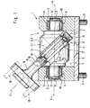
- the joint according to the invention shown in Figures 1 to 3 has this Housing 1, which consists of the spaced apart two side parts 2nd consists of each other through the base plate 3 having the recess 4 are connected.
- the housing 1 is with the side parts 2 and Base plate 3 penetrating fastening screws 5 on a not shown Connection structure attached.
- In two opposite mounting holes 9 of the side parts 2 is via its two pins 8 in its Middle part 7 reinforced cylindrical body 6 rotatably received.
- the cylindrical body 6 is with the pin 8 in the receiving bore 9 on
- a first roller bearing 10 is mounted, which consists of a radial bearing 11 and a Thrust bearing 12 is composed.
- the middle part 7 of the cylindrical body 6 has the inner race 14 of the second roller bearing 13, which under one Inclined at an angle to the axis of rotation X of the cylindrical body 6.
- the outer race 15 is formed by the outer ring 16, which at one point its periphery is connected to the connecting member 19, which via fastening screws 20 attachable to a connecting structure, not shown is.
- the cylindrical rollers 17 of the second roller bearing 13 are in the outer ring 16 arranged thrust washers 18 on both sides against axial displacement secured. All bearings, i.e. H. the radial bearing 11 and thrust bearing 12 existing first roller bearings 10 and the second roller bearing 13 are free of play designed so that a bearing clearance is avoided.
- the outer ring 16 of the second roller bearing 13 is pivotable about its axis Y, which in turn for Axis of rotation X of the cylindrical body 6 at the angle ⁇ ⁇ 90 ° and intersects with it at the intersection 21, which at the same time is the center of the middle part 7 of the cylindrical body 6.
- the longitudinal axis Z of the connecting member 19 also meets at the intersection 21 the other two axes X and Y. This ensures that when the spherical bearing moves, the outer ring 16 of the second rolling bearing 13 and that attached to him link 19 a wobble To run.
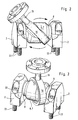
- FIGs 2 and 3 are two different perspective views Positions of the spherical bearing according to the invention shown, the housing 1 is shown without the base plate 3, d. H. the side walls 2 will directly with the help of fastening screws 22 on a connecting structure attached.
- 2 shows the joint in its left stop position, d. H. the outer ring 16 is inclined to the left and lies with its upper part almost on the left side part 2.
- the cylindrical body 6 swivels about its axis X, after a quarter turn the state is as in Figure 3 shown reached.
- the connecting link 19 is in a straight line Line hiked to the middle between the two side parts 2. To another quarter turn, d. H.
- the machine tool 23 shown in FIG. 4 is made of several each in tubes 24, 25 formed telescopic arms 26 are provided. These telescopic arms 26 are on the one hand on the frame 27 and on the other hand on the Tool holder 28 attached.
- the tool holder 28 is with a Not shown tool provided that is driven by the motor 29 becomes. By retracting or extending one or more telescopic arms 26 the tool holder 28 can be in any desired position in space move.
- the joints according to the invention with two degrees of freedom can fixed to the frame 27 in the illustrated tractor, for example become. In interaction with joints fastened to the tool holder 28 is ensured by their stiffness that the invention Joint can be loaded in both the pulling and pushing directions without unwanted deflections occur.
Landscapes
- Engineering & Computer Science (AREA)
- Mechanical Engineering (AREA)
- General Engineering & Computer Science (AREA)
- Rolling Contact Bearings (AREA)
Description
- einem in seinem Mittelteil verstärkt ausgebildeten zylindrischen Körper, der mit seinen gegenüberliegenden Zapfen schwenkbar um eine Achse X in zwei Aufnahmebohrungen eines Gehäuses über je ein erstes Wälzlager aufgenommen ist,
- einer im zylindrischen Körper angeordneten inneren Laufbahn für ein zweites Wälzlager, die zur Achse X geneigt verlaufend angeordnet ist,
- einem eine äußere Laufbahn des zweiten Wälzlagers bildenden Außenring, der schwenkbar um eine Achse Y angeordnet ist, wobei sich beide Achsen X, Y unter einem Winkel α ≤ 90° schneiden,
- einem an einer Umfangsstelle fest mit dem Außenring verbundenen, die Zug- oder Druckkraft übertragenden Verbindungsglied, dessen Achse Z im Mittelteil des zylindrischen Körpers einen gemeinsamen Schnittpunkt mit den Achsen X und Y aufweist, so dass bei einer Schwenkbewegung des zylindrischen Körpers der Außenring und das mit ihm verbundene Verbindungsglied eine Taumelbewegung ausführen
- Fig. 1
- einen Längsschnitt durch ein erfindungsgemäßes Gelenk;
- Fig. 2, 3
- eine perspektivische Darstellung des Gelenkes in zwei verschiedenen Stellungen und
- Fig. 4
- eine schematische Darstellung einer Werkzeugmaschine des Hexapode-Systems.
- 1
- Gehäuse
- 2
- Seitenteil
- 3
- Grundplatte
- 4
- Ausnehmung
- 5
- Befestigungsschraube
- 6
- zylindrischer Körper
- 7
- Mittelteil
- 8
- Zapfen
- 9
- Aufnahmebohrung
- 10
- erstes Wälzlager
- 11
- Radiallager
- 12
- Axiallager
- 13
- zweites Wälzlager
- 14
- innere Laufbahn
- 15
- äußere Laufbahn
- 16
- Außenring
- 17
- Zylinderrollen
- 18
- Anlaufscheibe
- 19
- Verbindungsglied
- 20
- Befestigungsschraube
- 21
- Schnittpunkt
- 22
- Befestigungsschraube
- 23
- Werkzeugmaschine
- 24
- Rohr
- 25
- Rohr
- 26
- Teleskoparm
- 27
- Rahmen
- 28
- Werkzeugaufnahme
- 29
- Motor
- X
- Schwenkachse
- Y
- Schwenkachse
- Z
- Längsachse
- α
- Winkel
Claims (8)
- Gelenk zur Übertragung von Zug- oder Druckkräften mit wenigstens zwei Freiheitsgraden, das folgende Merkmale aufweist,einem in seinem Mittelteil (7) verstärkt ausgebildeten zylindrischen Körper (6), der mit seinen gegenüberliegenden Zapfen (8) schwenkbar um eine Achse X in zwei Aufnahmebohrungen (9) eines Gehäuses (1) über je ein erstes Wälzlager (10) aufgenommen ist,einer im zylindrischen Körper (6) angeordneten inneren Laufbahn (14) für ein zweites Wälzlager (13), die zur Achse X geneigt verlaufend angeordnet ist,einem eine äußere Laufbahn (15) des zweiten Wälzlagers (13) bildenden Außenring (16), der schwenkbar um eine Achse Y angeordnet ist, wobei sich beide Achsen X,Y unter einem Winkel α ≤ 90° schneiden,einem an einer Umfangsstelle fest mit dem Außenring (16) verbundenen, die Zug- oder Druckkraft übertragenden Verbindungsglied (19), dessen Achse Z im Mittelteil (7) des zylindrischen Körpers (6) einen gemeinsamen Schnittpunkt (21) mit den Achsen X und Y aufweist, so dass bei einer Schwenkbewegung des zylindrischen Körpers (6) der Außenring (16) und das mit ihm verbundene Verbindungsglied (19) eine Taumelbewegung ausführen.
- Gelenk nach Anspruch 1 mit dem Gehäuse (1), das aus zwei voneinander in Richtung der X-Achse beabstandeten, die Aufnahmebohrungen (9) tragenden Seitenteilen (2) besteht, die durch eine Grundplatte (3) miteinander verbunden sind.
- Gelenk nach Anspruch 1 mit dem die Zapfen (8) aufnehmenden ersten Wälzlager (10), das als ein Radiallager (11) und als ein Axiallager (12) ausgebildet ist.
- Gelenk nach Anspruch 3 mit dem als Nadellager ausgebildeten Radial- (11) und Axiallager (12).
- Gelenk nach Anspruch 3 mit einem äußeren Laufring des Radiallagers (11) und einer Laufscheibe des Axiallagers (12), die durch einen spanlosen Formgebungsvorgang hergestellt sind.
- Gelenk nach Anspruch 1 mit dem zweiten Wälzlager (13), das als ein vollrolliges Zylinderrollenlager ausgebildet ist, dessen Zylinderrollen (17) gegen ein Verschieben in Richtung der Y-Achse durch zwei im Außenring (16) angeordnete Anlaufscheiben (18) gesichert sind.
- Gelenk nach Anspruch 1 mit erstem und zweitem Wälzlager (10,13), die spielfrei vorgespannt sind.
- Parallel Kinematik in die ein Gelenk nach einem der Ansprüche 1 bis 7 eingesetzt ist.
Applications Claiming Priority (3)
| Application Number | Priority Date | Filing Date | Title |
|---|---|---|---|
| DE10007005 | 2000-02-16 | ||
| DE10007005A DE10007005A1 (de) | 2000-02-16 | 2000-02-16 | Gelenk |
| PCT/EP2000/013097 WO2001061204A1 (de) | 2000-02-16 | 2000-12-21 | Gelenk |
Publications (2)
| Publication Number | Publication Date |
|---|---|
| EP1264116A1 EP1264116A1 (de) | 2002-12-11 |
| EP1264116B1 true EP1264116B1 (de) | 2003-07-16 |
Family
ID=7631159
Family Applications (1)
| Application Number | Title | Priority Date | Filing Date |
|---|---|---|---|
| EP00990809A Expired - Lifetime EP1264116B1 (de) | 2000-02-16 | 2000-12-21 | Gelenk |
Country Status (4)
| Country | Link |
|---|---|
| EP (1) | EP1264116B1 (de) |
| AU (1) | AU2001230154A1 (de) |
| DE (2) | DE10007005A1 (de) |
| WO (1) | WO2001061204A1 (de) |
Family Cites Families (4)
| Publication number | Priority date | Publication date | Assignee | Title |
|---|---|---|---|---|
| US4551058A (en) * | 1983-07-20 | 1985-11-05 | Robotics, Inc. | Low cost articulating/articulating and rotating wrist mechanism for automatic machine tool and automatic machine tool employing the same |
| US5028180A (en) * | 1989-09-01 | 1991-07-02 | Sheldon Paul C | Six-axis machine tool |
| US5987726A (en) * | 1996-03-11 | 1999-11-23 | Fanuc Robotics North America, Inc. | Programmable positioner for the stress-free assembly of components |
| JP4108927B2 (ja) * | 1997-09-24 | 2008-06-25 | ミシュラン アーベーエス | 2つの接続部品間を関節接合する手段およびその手段で取り付けた自動車ホイールサスペンション |
-
2000
- 2000-02-16 DE DE10007005A patent/DE10007005A1/de not_active Withdrawn
- 2000-12-21 EP EP00990809A patent/EP1264116B1/de not_active Expired - Lifetime
- 2000-12-21 AU AU2001230154A patent/AU2001230154A1/en not_active Abandoned
- 2000-12-21 DE DE50002950T patent/DE50002950D1/de not_active Expired - Lifetime
- 2000-12-21 WO PCT/EP2000/013097 patent/WO2001061204A1/de not_active Ceased
Also Published As
| Publication number | Publication date |
|---|---|
| AU2001230154A1 (en) | 2001-08-27 |
| DE50002950D1 (de) | 2003-08-21 |
| EP1264116A1 (de) | 2002-12-11 |
| WO2001061204A1 (de) | 2001-08-23 |
| DE10007005A1 (de) | 2001-08-23 |
Similar Documents
| Publication | Publication Date | Title |
|---|---|---|
| EP0966619B1 (de) | Wälzgelagertes gelenk | |
| DE2343540C3 (de) | Gleichgang-Universalgelenk des Tripod-Typs | |
| EP3846974B1 (de) | Gelenklagerung für einen roboter mit elastisch komprimierbarem vorspannelement | |
| DE60221803T2 (de) | Nockenstabzentriermechanismus | |
| DE10235191B4 (de) | Roboter | |
| DE2327372A1 (de) | Homokinetisches gelenk | |
| DE2855113A1 (de) | Aus schichten bestehende elastomerlageranordnung fuer hubschrauberrotoreinrichtungen u.dgl. | |
| DE4228230A1 (de) | Universalgelenk | |
| DE4300793B4 (de) | Zentrierfeder für Triplan-Kugelgleichlaufgelenke | |
| DE19506815A1 (de) | Homokinetisches Gelenk und dieses Gelenk verwendende Axialkolbenpumpe | |
| DE69231593T2 (de) | Rüttelfreies tripodegleichlaufgelenk | |
| DE3219561C2 (de) | ||
| DE10125320A1 (de) | Axial verstellbare Achsanordnung mit Kugelfederverbindung | |
| DE1960247A1 (de) | Homokinetisches Wellengelenk | |
| EP4118348B1 (de) | Schwenkwiegenlagerung und verfahren zur herstellung einer synchronisatonsvorrichtung einer schwenkwiegenlagerung | |
| DE2039965B2 (de) | Gleichlaufgelenkkupplung | |
| DE2654990C2 (de) | Gelenkkupplung | |
| DE10002757B4 (de) | Kugelgelenk | |
| EP2270350B1 (de) | Gleichlauf-Universalgelenk | |
| EP1264116A1 (de) | Gelenk | |
| DE4210250A1 (de) | Schwenkkupplung | |
| DE10058317A1 (de) | Universalgelenk | |
| DE69811737T2 (de) | Förderkette, anordnung und verfahren zum verbinden der glieder | |
| DE19950358A1 (de) | Universalgelenk und Maschine vom Parallelvorrichtungstyp mit einem solchen Gelenk | |
| WO2000022312A1 (de) | Kreuzgelenk |
Legal Events
| Date | Code | Title | Description |
|---|---|---|---|
| PUAI | Public reference made under article 153(3) epc to a published international application that has entered the european phase |
Free format text: ORIGINAL CODE: 0009012 |
|
| 17P | Request for examination filed |
Effective date: 20020720 |
|
| AK | Designated contracting states |
Kind code of ref document: A1 Designated state(s): AT BE CH CY DE DK ES FI FR GB GR IE IT LI LU MC NL PT SE TR |
|
| AX | Request for extension of the european patent |
Free format text: AL;LT;LV;MK;RO;SI |
|
| GRAH | Despatch of communication of intention to grant a patent |
Free format text: ORIGINAL CODE: EPIDOS IGRA |
|
| GRAH | Despatch of communication of intention to grant a patent |
Free format text: ORIGINAL CODE: EPIDOS IGRA |
|
| GRAA | (expected) grant |
Free format text: ORIGINAL CODE: 0009210 |
|
| AK | Designated contracting states |
Designated state(s): CH DE FR GB LI SE |
|
| REG | Reference to a national code |
Ref country code: GB Ref legal event code: FG4D Free format text: NOT ENGLISH |
|
| REG | Reference to a national code |
Ref country code: CH Ref legal event code: EP |
|
| REG | Reference to a national code |
Ref country code: CH Ref legal event code: NV Representative=s name: TROESCH SCHEIDEGGER WERNER AG |
|
| REG | Reference to a national code |
Ref country code: IE Ref legal event code: FG4D Free format text: GERMAN |
|
| REF | Corresponds to: |
Ref document number: 50002950 Country of ref document: DE Date of ref document: 20030821 Kind code of ref document: P |
|
| REG | Reference to a national code |
Ref country code: SE Ref legal event code: TRGR |
|
| GBT | Gb: translation of ep patent filed (gb section 77(6)(a)/1977) |
Effective date: 20031117 |
|
| LTIE | Lt: invalidation of european patent or patent extension |
Effective date: 20030716 |
|
| REG | Reference to a national code |
Ref country code: IE Ref legal event code: FD4D |
|
| ET | Fr: translation filed | ||
| PLBE | No opposition filed within time limit |
Free format text: ORIGINAL CODE: 0009261 |
|
| STAA | Information on the status of an ep patent application or granted ep patent |
Free format text: STATUS: NO OPPOSITION FILED WITHIN TIME LIMIT |
|
| 26N | No opposition filed |
Effective date: 20040419 |
|
| REG | Reference to a national code |
Ref country code: FR Ref legal event code: CD |
|
| PGFP | Annual fee paid to national office [announced via postgrant information from national office to epo] |
Ref country code: SE Payment date: 20061206 Year of fee payment: 7 |
|
| PGFP | Annual fee paid to national office [announced via postgrant information from national office to epo] |
Ref country code: FR Payment date: 20061208 Year of fee payment: 7 |
|
| PGFP | Annual fee paid to national office [announced via postgrant information from national office to epo] |
Ref country code: GB Payment date: 20061220 Year of fee payment: 7 |
|
| EUG | Se: european patent has lapsed | ||
| GBPC | Gb: european patent ceased through non-payment of renewal fee |
Effective date: 20071221 |
|
| PG25 | Lapsed in a contracting state [announced via postgrant information from national office to epo] |
Ref country code: SE Free format text: LAPSE BECAUSE OF NON-PAYMENT OF DUE FEES Effective date: 20071222 |
|
| REG | Reference to a national code |
Ref country code: FR Ref legal event code: ST Effective date: 20081020 |
|
| PG25 | Lapsed in a contracting state [announced via postgrant information from national office to epo] |
Ref country code: GB Free format text: LAPSE BECAUSE OF NON-PAYMENT OF DUE FEES Effective date: 20071221 |
|
| PGFP | Annual fee paid to national office [announced via postgrant information from national office to epo] |
Ref country code: CH Payment date: 20081230 Year of fee payment: 9 |
|
| PG25 | Lapsed in a contracting state [announced via postgrant information from national office to epo] |
Ref country code: FR Free format text: LAPSE BECAUSE OF NON-PAYMENT OF DUE FEES Effective date: 20071231 |
|
| REG | Reference to a national code |
Ref country code: CH Ref legal event code: PL |
|
| PG25 | Lapsed in a contracting state [announced via postgrant information from national office to epo] |
Ref country code: CH Free format text: LAPSE BECAUSE OF NON-PAYMENT OF DUE FEES Effective date: 20091231 Ref country code: LI Free format text: LAPSE BECAUSE OF NON-PAYMENT OF DUE FEES Effective date: 20091231 |
|
| REG | Reference to a national code |
Ref country code: DE Ref legal event code: R081 Ref document number: 50002950 Country of ref document: DE Owner name: SCHAEFFLER TECHNOLOGIES AG & CO. KG, DE Free format text: FORMER OWNER: SCHAEFFLER TECHNOLOGIES GMBH & CO. KG, 91074 HERZOGENAURACH, DE Effective date: 20120828 Ref country code: DE Ref legal event code: R081 Ref document number: 50002950 Country of ref document: DE Owner name: SCHAEFFLER TECHNOLOGIES GMBH & CO. KG, DE Free format text: FORMER OWNER: SCHAEFFLER TECHNOLOGIES GMBH & CO. KG, 91074 HERZOGENAURACH, DE Effective date: 20120828 |
|
| REG | Reference to a national code |
Ref country code: DE Ref legal event code: R081 Ref document number: 50002950 Country of ref document: DE Owner name: SCHAEFFLER TECHNOLOGIES AG CO. KG, DE Free format text: FORMER OWNER: SCHAEFFLER TECHNOLOGIES AG CO. KG, 91074 HERZOGENAURACH, DE Effective date: 20140218 Ref country code: DE Ref legal event code: R081 Ref document number: 50002950 Country of ref document: DE Owner name: SCHAEFFLER TECHNOLOGIES GMBH & CO. KG, DE Free format text: FORMER OWNER: SCHAEFFLER TECHNOLOGIES AG & CO. KG, 91074 HERZOGENAURACH, DE Effective date: 20140218 Ref country code: DE Ref legal event code: R081 Ref document number: 50002950 Country of ref document: DE Owner name: SCHAEFFLER TECHNOLOGIES AG & CO. KG, DE Free format text: FORMER OWNER: SCHAEFFLER TECHNOLOGIES AG & CO. KG, 91074 HERZOGENAURACH, DE Effective date: 20140218 |
|
| REG | Reference to a national code |
Ref country code: DE Ref legal event code: R081 Ref document number: 50002950 Country of ref document: DE Owner name: SCHAEFFLER TECHNOLOGIES AG & CO. KG, DE Free format text: FORMER OWNER: SCHAEFFLER TECHNOLOGIES GMBH & CO. KG, 91074 HERZOGENAURACH, DE Effective date: 20150211 |
|
| PGFP | Annual fee paid to national office [announced via postgrant information from national office to epo] |
Ref country code: DE Payment date: 20170228 Year of fee payment: 17 |
|
| REG | Reference to a national code |
Ref country code: DE Ref legal event code: R119 Ref document number: 50002950 Country of ref document: DE |
|
| PG25 | Lapsed in a contracting state [announced via postgrant information from national office to epo] |
Ref country code: DE Free format text: LAPSE BECAUSE OF NON-PAYMENT OF DUE FEES Effective date: 20180703 |