EP1262811B1 - Auf Totalreflexion beruhender optischer Schalter mit bewegtem Tropfen - Google Patents
Auf Totalreflexion beruhender optischer Schalter mit bewegtem Tropfen Download PDFInfo
- Publication number
- EP1262811B1 EP1262811B1 EP02002173A EP02002173A EP1262811B1 EP 1262811 B1 EP1262811 B1 EP 1262811B1 EP 02002173 A EP02002173 A EP 02002173A EP 02002173 A EP02002173 A EP 02002173A EP 1262811 B1 EP1262811 B1 EP 1262811B1
- Authority
- EP
- European Patent Office
- Prior art keywords
- droplet
- trench
- waveguide
- optical switch
- gap
- Prior art date
- Legal status (The legal status is an assumption and is not a legal conclusion. Google has not performed a legal analysis and makes no representation as to the accuracy of the status listed.)
- Expired - Lifetime
Links
Images


Classifications
-
- G—PHYSICS
- G02—OPTICS
- G02B—OPTICAL ELEMENTS, SYSTEMS OR APPARATUS
- G02B6/00—Light guides; Structural details of arrangements comprising light guides and other optical elements, e.g. couplings
- G02B6/24—Coupling light guides
- G02B6/26—Optical coupling means
- G02B6/35—Optical coupling means having switching means
- G02B6/3538—Optical coupling means having switching means based on displacement or deformation of a liquid
-
- G—PHYSICS
- G02—OPTICS
- G02B—OPTICAL ELEMENTS, SYSTEMS OR APPARATUS
- G02B26/00—Optical devices or arrangements for the control of light using movable or deformable optical elements
- G02B26/004—Optical devices or arrangements for the control of light using movable or deformable optical elements based on a displacement or a deformation of a fluid
-
- G—PHYSICS
- G02—OPTICS
- G02B—OPTICAL ELEMENTS, SYSTEMS OR APPARATUS
- G02B6/00—Light guides; Structural details of arrangements comprising light guides and other optical elements, e.g. couplings
- G02B6/24—Coupling light guides
- G02B6/26—Optical coupling means
- G02B6/35—Optical coupling means having switching means
- G02B6/354—Switching arrangements, i.e. number of input/output ports and interconnection types
- G02B6/3544—2D constellations, i.e. with switching elements and switched beams located in a plane
-
- G—PHYSICS
- G02—OPTICS
- G02B—OPTICAL ELEMENTS, SYSTEMS OR APPARATUS
- G02B6/00—Light guides; Structural details of arrangements comprising light guides and other optical elements, e.g. couplings
- G02B6/24—Coupling light guides
- G02B6/26—Optical coupling means
- G02B6/35—Optical coupling means having switching means
- G02B6/3564—Mechanical details of the actuation mechanism associated with the moving element or mounting mechanism details
- G02B6/3568—Mechanical details of the actuation mechanism associated with the moving element or mounting mechanism details characterised by the actuating force
- G02B6/357—Electrostatic force
-
- G—PHYSICS
- G02—OPTICS
- G02B—OPTICAL ELEMENTS, SYSTEMS OR APPARATUS
- G02B6/00—Light guides; Structural details of arrangements comprising light guides and other optical elements, e.g. couplings
- G02B6/24—Coupling light guides
- G02B6/26—Optical coupling means
- G02B6/35—Optical coupling means having switching means
- G02B6/3564—Mechanical details of the actuation mechanism associated with the moving element or mounting mechanism details
- G02B6/3568—Mechanical details of the actuation mechanism associated with the moving element or mounting mechanism details characterised by the actuating force
- G02B6/3576—Temperature or heat actuation
-
- G—PHYSICS
- G02—OPTICS
- G02B—OPTICAL ELEMENTS, SYSTEMS OR APPARATUS
- G02B6/00—Light guides; Structural details of arrangements comprising light guides and other optical elements, e.g. couplings
- G02B6/24—Coupling light guides
- G02B6/26—Optical coupling means
- G02B6/35—Optical coupling means having switching means
- G02B6/3596—With planar waveguide arrangement, i.e. in a substrate, regardless if actuating mechanism is outside the substrate
Definitions
- the present invention relates to optical switches, and more particularly, to an improved cross-point switching element.
- Optical fibers provide significantly higher data rates than electronic paths.
- effective utilization of the greater bandwidth inherent in optical signal paths requires optical cross-connect switches.
- the switching of signals between optical fibers utilizes an electrical cross-connect switch.
- the optical signals are first converted to electrical signals. After the electrical signals have been switched, the signals are again converted back to optical signals that are transmitted via the optical fibers.
- the electrical cross-connect switches utilize highly parallel, and highly costly, switching arrangements. However, even with such parallel architectures, the cross-connect switches remain a bottleneck.
- optical cross-connect switches have been proposed; however, none of these has successfully filled the need for an inexpensive, reliable, optical cross-connect switch.
- One class of optical cross-connects depends on wavelength division multiplexing (WDM) to effect the switching.
- WDM wavelength division multiplexing
- this type of system requires that the optical signals being switched have different wavelengths.
- this type of system requires the signals to be converted to the desired wavelength, switched, and then be re-converted to the original wavelength. This conversion process complicates the system and increases the cost.
- a second type of optical cross-connect utilizes total internal reflection (TIR) switching elements.
- TIR element consists of a waveguide with a switchable boundary. Light strikes the boundary at an angle. In the first state, the boundary separates two regions having substantially different indices of refraction. In this state, the incident angle is greater than the critical angle of TIR, the light is reflected off of the boundary and thus changes direction. In the second state, the two regions separated by the boundary have the same index of refraction and the light continues in a straight line through the boundary.
- the critical angle of TIR depends on the difference in the index of refraction of the two regions. To obtain a large change in direction, the region behind the boundary must be switchable between an index of refraction equal to that of the waveguide and an index of refraction that is markedly smaller than that of the waveguide.
- TIR taught in this patent utilizes thermal activation to displace liquid from a gap at the intersection of a first optical waveguide and a second optical waveguide.
- a trench is cut through a waveguide.
- the trench is filled with an index-matching liquid.
- a bubble is generated at the cross-point by heating the index matching liquid with a localized heater. The bubble must be removed from the cross-point to switch the cross-point from the reflecting to the transmitting state and thus change the direction of the output optical signal.
- Switches based on a gas-vapor transition have a number of problems.
- an optical switch is constructed from first and second waveguides.
- the first and second waveguides have ends disposed across a gap such that light traversing the first waveguide enters the second waveguide when the gap is filled with a liquid having a first index of refraction, whereas light traversing the first waveguide is reflected by the gap when the gap is filled with a material having a second index of refraction that is substantially different from the first index of refraction.
- the gap is part of a trench that contains a liquid droplet made from a droplet material having the first index of refraction. The droplet is located in the trench and is movable between the first and second positions in the trench, the droplet filling the gap in the first position.
- the gap is filled with a material having the second index of refraction when the droplet is in the second position.
- the droplet may be moved using an electric field generated by a plurality of electrodes arranged such that an electrical potential applied between a first pair of the electrodes creates an electric field in a region of the trench containing the first position.
- the droplet can also be moved by differentially heating two edges of the droplet so as to create a net force on the droplet in a direction parallel to the direction of the trench. The heating can be accomplished by illuminating one edge of the droplet with light of a wavelength that is absorbed by the droplet material.
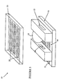
- Switching element 210 is constructed from three waveguides 211-213 that are fabricated in a planar lightwave circuit on top of a substrate.
- the substrate is preferably a silica, but other materials, such as silicon, may be used.
- the waveguides are defined by two cladding layers and a core layer. To simplify the drawing, the individual layers have been omitted.
- the fabrication of such waveguides in silica is well known to the art, and hence will not be discussed in detail here. For example, Hitachi Cable and Photonic Integration Research, Inc. in Columbus, Ohio have demonstrated waveguides in SiO 2 on silica and silicon substrates.
- the core is primarily SiO 2 doped with another material, such as Ge or TiO 2 .
- the cladding material is SiO 2 , doped with another material such as B 2 O 3 and/or P 2 O 5 . Because the core material has a refractive index that is different from the refractive index of the cladding layers, optical signals will be guided along waveguides 211-213.
- a trench 214 is etched through the waveguide and preferably into the silicon substrate.
- Trench 214 is positioned such that a light signal travelling down waveguide 211 will be reflected into waveguide 213 if the index of refraction of the material filling trench 214 is substantially different from the index of refraction of the waveguides as shown in Figure 1.
- This state of the switching element will be referred to as the "reflecting" state. If, however, the intersection of the trench and the waveguides is filled with a material having an index of refraction that matches that of the core of the waveguides, the light signal will pass through trench 214 and exit via waveguide 212 as shown in Figure 2. This state of the switching element will be referred to as the "transmitting" state.
- the angle at which waveguides 211 and 213 intersect trench 214 depends on the difference in the index of refraction between the waveguide material and the material used to create the reflecting state in the trench.
- the angles of incidence of the waveguides and the position of the trench are chosen such that light incident on the trench wall from waveguide 211 is totally reflected into waveguide 213. This angle is typically between 53 and 75 degrees with respect to the normal direction of the trench wall.
- Waveguide 219 is used to construct cross-connect switches utilizing a two-dimensional array of cross-point switching elements.
- An array of this type is typically constructed as a plurality of rows and columns of cross-point switching elements. The rows and columns are connected via row and column waveguides.
- the cross-connect switch connects the signals input on the row waveguides to the column waveguides. The specific switching pattern depends on the state of the switching elements.
- the index matching material may be displaced from the intersection by forming a bubble 215 at the intersection with the aid of a heating element 216.
- Heating element 216 draws power both to vaporize the index matching liquid and to maintain the bubble during the time the cross-point is to remain in the reflective state.
- the present invention overcomes these problems by utilizing a dielectric droplet of index matching liquid that is moved in the trench by applying electric fields to the droplet. When the fields are removed, the droplet remains at its last position, and hence, the cross-point will maintain its state even if power is removed. In addition, the power consumption of the device is substantially lower than vapor-based bubble systems, since the power source does not have to vaporize the index matching liquid.
- Figure 3 is a partially exploded perspective view of a portion of a cross-point 10 according to the present invention.
- Figures 4 and 5 are top views of a cross-point according to the present invention in the reflecting and transmitting states, respectively.
- the present invention is based on the observation that a droplet of dielectric will move into an electric field.
- a dielectric droplet 12 is confined to a trench 18.
- the transmitting state the droplet is moved such that it covers the waveguide 13 as shown in Figure 5.
- the index of refraction of the droplet is chosen to match that of the waveguide, and hence, light will pass from waveguide 13 to waveguide 14.
- the interface between the gas in the trench and the waveguide causes light in the waveguide to be reflected down waveguide 16.
- the droplet is moved by applying an AC electric field across a portion of the droplet.
- the electric field is generated by applying the appropriate potentials across selected one of the electrodes 22 that are deposited on the top of trench cover 23 and the electrodes 21 on the bottom of the trench.
- a DC electric field can be utilized to move the droplet if the droplet is constructed from a perfect dielectric. Unfortunately, most of the materials that can be used for the droplet have sufficient conductivity to allow ions to move within the droplet. If a DC field is used, these ions will migrate to the surface of the droplet and shield the droplet from the electric field.
- an AC field that has a polarity that changes in a time that is short compared to the time needed for ions or other carriers to migrate a significant distance within the droplet must be used.
- a field with a frequency greater than 1 kHz is utilized.
- Figures 6-8 are cross-sectional views of the waveguide through line 51-52 shown in Figure 4.
- Figure 6 illustrates the field pattern used to move droplet 12 into a position at which it causes the waveguide to be transmitting.
- the droplet is initially to the right of the waveguide.
- By applying a potential difference across the top and bottom electrodes in the region shown at the droplet will experience a force that tends to move the droplet to the left.
- the electric potentials are removed from the electrodes and the cross-point will remain in the transmitting state as shown in Figure 7.
- the electrodes shown at 31 in Figure 8 are energized thereby applying a force that moves the droplet to the right.
- the electrodes are energized in sequence as the droplet moves such that approximately half of the droplet is subjected to the electric field. This arrangement maximizes the force on the droplet, and hence, the speed of the droplet. Once the droplet has moved to the desired final position, the electrodes around the desired position are energized until the droplet's motion ceases. These electrodes are shown at 30 in Figure 6.
- a cross-connect switch can be constructed from an array of cross-points in which a number of the cross-points share the same trench. In this case, it is advantageous to isolate the operation of the cross-points that share a trench. If droplet 12 fills the trench, then its motion will compress the gas on one side of the droplet and reduce the gas pressure on the other side. This pressure differential can cause a droplet in the same trench to move even in the absence of an electric field on that droplet. In addition, the pressure differential inhibits the motion of the droplet, and hence, larger electric fields are needed to move the droplet.
- an air gap is included above the droplet as shown at 60 in Figure 6. This provides an air passage that prevents a pressure differential from forming across the droplet when the droplet moves.
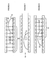
- Figure 9 is a top cross-sectional view of a trench 101 containing a droplet 102 that moves to match the index of refraction across the gap in waveguide 104.
- Figures 10 and 11 are side cross-sectional views of trench 101 through line 115-116. If the droplet is at a uniform temperature, the surface tension in the surface at the liquid-gas interface 105 is the same as the surface tension at interface 107.
- a heating element shown at 106 may be used to heat the droplet edge.
- a pair of electrodes 108-109 can be used to stop the droplet by applying a signal across the electrodes to generate an electric field in the desired region.
- the electrodes may be viewed as forming the plates of a capacitor in which the droplet is the dielectric.
- the electric field applies a force to the dielectric that holds the dielectric between the plates of the capacitor. This is the force that moved the droplet in the embodiments discussed above. In those embodiments, the droplet was only part of the way into the capacitor, and hence, the force pulled the remaining distance. In this embodiment, the field traps the droplet. Once the droplet has reached thermal equilibrium, the field can be removed.
- a second heater 126 can be used to reverse the direction of motion to remove the droplet from the region of the waveguide.
- a second set of electrodes shown at 129 and 130 can be used to "catch" the droplet and hold it at the reflecting position.
- the above-described embodiments of the present invention utilize localized heaters to differentially heat the edges of the droplet; however, other mechanisms can be utilized.
- Figure 13 is a cross-sectional view of the trench 151 of another embodiment of the present invention.
- the cross-point utilizes a droplet that is constructed from a material that has an absorption band at a control wavelength while remaining clear at the wavelength of the light being transmitted through waveguide 104.
- droplet 154 is irradiated with light of the control wavelength from one end, that end of the droplet will be preferentially heated, since the droplet will absorb the light before it reaches the other end of the droplet.
- the heating can be accomplished by including two small light sources 161 and 162, one at each end of the trench. LEDs or laser diodes can be utilized for these light sources. In the embodiment shown in Figure 13, pairs of electrodes shown at 171 and 172 are utilized to trap the droplet at the two positions corresponding to the transmitting and reflecting states of the cross-point.
- the above-described droplets are generated from a dielectric material that has an index of refraction that matches that of the waveguide.
- a dielectric material that has an index of refraction that matches that of the waveguide.
- Such materials are well known in the optical arts, and hence, will not be discussed in detail here. Suitable materials are available from Cargille Laboratories, Inc. Scientific Div. 55 Commerce Rd. Cedar Grove, NJ 07009-1289. It should be noted that an exact match can be obtained by mixing two different dielectric liquids that have different indices of refraction to obtain a droplet having an index of refraction that is intermediate between the component indices.
- any dye that is soluble in the droplet material and provides the desired absorption and transmission bands may be utilized. Suitable dyes are available from Aldrich Chemical and Merck.
- the present invention utilizes a liquid droplet surrounded by a gas.
- the present invention may be practiced with a vacuum in the trench or with a suspension liquid in the trench provided the liquid has an index of refraction that is sufficiently less than the index of refraction of the liquid in the droplet.
- the liquid of the droplet must not be soluble in the suspension liquid.
- the dielectric constant of the liquid of the droplet must be greater than that of the suspension liquid if electric fields are utilized to move the droplet or hold the droplet in place.
Landscapes
- Physics & Mathematics (AREA)
- General Physics & Mathematics (AREA)
- Optics & Photonics (AREA)
- Mechanical Light Control Or Optical Switches (AREA)
Claims (11)
- Optischer Schalter (10), der folgendes umfaßt:einen ersten und einen zweiten Waveguide (13, 14) mit Enden, die quer über eine Lücke so angeordnet sind, daß Licht, das dem ersten Waveguide (13) folgt, in den zweiten Waveguide (14) eindringt, wenn die Lücke mit einer Flüssigkeit gefüllt ist, die einen ersten Brechungsindex aufweist, während Licht, welches dem ersten Waveguide (13) folgt, von der Lücke reflektiert wird, wenn darin die Flüssigkeit nicht vorhanden ist, wobei die Lücke ein Teil eines Grabens (18) in einem Substrat ist; undeinen Flüssigkeitstropfen (12), der ein Material mit dem ersten Brechungsindex aufweist, wobei sich der Tropfen (12) in dem Graben (18) befindet und sich zwischen einer ersten und einer zweiten Position in dem Graben (18) bewegen kann, der Tropfen (12) die Lükke in der ersten Position ausfüllt und der Tropfen (12) in der zweiten Position von der Lücke entfernt ist, wobei der Tropfen (12) einen ersten und einen zweiten Rand (105, 107) aufweist, die lateral quer über den Graben (18) angeordnet sind, und wobei der optische Schalter (10) weiterhin ein erstes Paar von Elektroden (30, 171) umfaßt, um ein elektrisches Feld über einen Teil des Flüssigkeitstropfens (12) einschließlich des ersten Rands (105), jedoch nicht über den zweiten Rand (107), anzulegen.
- Optischer Schalter (10) nach Anspruch 1, bei dem das Paar von Elektroden (30, 171) so eingerichtet ist, daß ein elektrisches Potential, das zwischen dem Paar der Elektroden (31, 172) angelegt wird, ein elektrisches Feld in einem Bereich des Grabens (18) erzeugt, der die erste Position umfaßt, jedoch nicht in dem Bereich des Grabens (18), der die zweite Position umfaßt.
- Optischer Schalter (10) nach einem der vorhergehenden Ansprüche, bei dem ein elektrisches Potential, das zwischen einem zweiten Paar von Elektroden (31, 172) angelegt wird, ein elektrisches Feld an einer Position erzeugt, die von der ersten Position entfernt ist, jedoch nicht in dem Bereich des Grabens (18), der die erste Position umfaßt.
- Optischer Schalter (10), der folgendes umfaßt:einen ersten und einen zweiten Waveguide (13, 14) mit Enden, die quer über eine Lücke so angeordnet sind, daß Licht, das dem ersten Waveguide (13) folgt, in den zweiten Waveguide (14) eindringt, wenn die Lücke mit einer Flüssigkeit gefüllt ist, die einen ersten Brechungsindex aufweist, während Licht, welches dem ersten Waveguide (13) folgt, von der Lücke reflektiert wird, wenn darin die Flüssigkeit nicht vorhanden ist, wobei die Lücke ein Teil eines Grabens (18) in dem Substrat ist; undeinen Flüssigkeitstropfen (12), der ein Tropfenmaterial mit dem ersten Brechungsindex aufweist, wobei sich der Tropfen (12) in dem Graben (18) befindet und sich zwischen einer ersten und einer zweiten Position in dem Graben (18) bewegen kann, der Tropfen (12) die Lücke in der ersten Position ausfüllt und der Tropfen (12) in der zweiten Position von der Lücke entfernt ist, wobei der Tropfen (12) einen ersten und einen zweiten Rand (105, 107) aufweist, die lateral quer über den Graben (18) angeordnet sind, und wobei der optische Schalter (10) weiterhin einen Heizer (106, 161, 126, 162) zum differenzierten Heizen des ersten und des zweiten Randes (105, 107) des Tropfens (12) umfaßt.
- Optischer Schalter (10) nach Anspruch 4, bei dem der Heizer (161, 162) eine Lichtquelle zum Beleuchten des Tropfens (12) mit Licht einer ersten Wellenlänge umfaßt, die von dem Tropfenmaterial absorbiert wird, wobei das Tropfenmaterial transparent für Licht einer zweiten Wellenlänge ist, die sich von der ersten Wellenlänge unterscheidet.
- Optischer Schalter (10) nach Anspruch 4 oder 5, der weiterhin mehrere Elektroden (30, 171) umfaßt, die so eingerichtet sind, daß ein elektrisches Potential, das zwischen einem ersten Paar der Elektroden (30, 171) angelegt wird, ein elektrisches Feld in einem Bereich des Grabens (18) erzeugt, der die erste Position umfaßt.
- Optischer Schalter (10) nach einem der Ansprüche 1 bis 6, bei dem der Graben (18) mit einem Gas gefüllt ist.
- Optischer Schalter (10) nach einem der Ansprüche 1 bis 6, bei dem der Graben (18) mit einer Flüssigkeit gefüllt ist, die einen Brechungsindex aufweist, der geringer als der erste Brechungsindex ist.
- Optischer Schalter (10) nach einem der Ansprüche 1 bis 6, bei dem der Graben (18) evakuiert ist.
- Optischer Schalter (10) nach einem der vorhergehenden Ansprüche, der weiterhin einen dritten Waveguide (16) umfaßt, der so angeordnet ist, daß Licht aus dem ersten Waveguide (13), das von der Lücke reflektiert wird, in den dritten Waveguide reflektiert wird.
- Optischer Schalter (10) nach einem der vorhergehenden Ansprüche,
bei dem der Graben (18) mit einem Gas gefüllt ist, und
bei dem der Graben (18) einen Gasdurchgang (60) aufweist, der es dem Gas ermöglicht, sich um den Tropfen (12) zu bewegen, wenn sich der Tropfen (12) in dem Graben bewegt.
Priority Applications (1)
| Application Number | Priority Date | Filing Date | Title |
|---|---|---|---|
| EP03023270A EP1385036B1 (de) | 2001-05-31 | 2002-01-29 | Auf Totalreflexion beruhender optischer Schalter mit bewegtem Tropfen |
Applications Claiming Priority (2)
| Application Number | Priority Date | Filing Date | Title |
|---|---|---|---|
| US871486 | 2001-05-31 | ||
| US09/871,486 US6647165B2 (en) | 2001-05-31 | 2001-05-31 | Total internal reflection optical switch utilizing a moving droplet |
Related Child Applications (1)
| Application Number | Title | Priority Date | Filing Date |
|---|---|---|---|
| EP03023270A Division EP1385036B1 (de) | 2001-05-31 | 2002-01-29 | Auf Totalreflexion beruhender optischer Schalter mit bewegtem Tropfen |
Publications (2)
| Publication Number | Publication Date |
|---|---|
| EP1262811A1 EP1262811A1 (de) | 2002-12-04 |
| EP1262811B1 true EP1262811B1 (de) | 2005-03-23 |
Family
ID=25357556
Family Applications (2)
| Application Number | Title | Priority Date | Filing Date |
|---|---|---|---|
| EP03023270A Expired - Lifetime EP1385036B1 (de) | 2001-05-31 | 2002-01-29 | Auf Totalreflexion beruhender optischer Schalter mit bewegtem Tropfen |
| EP02002173A Expired - Lifetime EP1262811B1 (de) | 2001-05-31 | 2002-01-29 | Auf Totalreflexion beruhender optischer Schalter mit bewegtem Tropfen |
Family Applications Before (1)
| Application Number | Title | Priority Date | Filing Date |
|---|---|---|---|
| EP03023270A Expired - Lifetime EP1385036B1 (de) | 2001-05-31 | 2002-01-29 | Auf Totalreflexion beruhender optischer Schalter mit bewegtem Tropfen |
Country Status (4)
| Country | Link |
|---|---|
| US (1) | US6647165B2 (de) |
| EP (2) | EP1385036B1 (de) |
| JP (1) | JP2003107375A (de) |
| DE (2) | DE60203383T2 (de) |
Families Citing this family (22)
| Publication number | Priority date | Publication date | Assignee | Title |
|---|---|---|---|---|
| US6674933B2 (en) * | 2001-09-27 | 2004-01-06 | Agilent Technologies, Inc. | Optical switch controlled by selective activation and deactivation of an optical source |
| US7019235B2 (en) | 2003-01-13 | 2006-03-28 | Agilent Technologies, Inc. | Photoimaged channel plate for a switch |
| US6774325B1 (en) * | 2003-04-14 | 2004-08-10 | Agilent Technologies, Inc. | Reducing oxides on a switching fluid in a fluid-based switch |
| US6768068B1 (en) * | 2003-04-14 | 2004-07-27 | Agilent Technologies, Inc. | Method and structure for a slug pusher-mode piezoelectrically actuated liquid metal switch |
| US6841746B2 (en) * | 2003-04-14 | 2005-01-11 | Agilent Technologies, Inc. | Bent switching fluid cavity |
| US6818844B2 (en) * | 2003-04-14 | 2004-11-16 | Agilent Technologies, Inc. | Method and structure for a slug assisted pusher-mode piezoelectrically actuated liquid metal optical switch |
| US6794591B1 (en) * | 2003-04-14 | 2004-09-21 | Agilent Technologies, Inc. | Fluid-based switches |
| US6750413B1 (en) * | 2003-04-25 | 2004-06-15 | Agilent Technologies, Inc. | Liquid metal micro switches using patterned thick film dielectric as channels and a thin ceramic or glass cover plate |
| US6777630B1 (en) * | 2003-04-30 | 2004-08-17 | Agilent Technologies, Inc. | Liquid metal micro switches using as channels and heater cavities matching patterned thick film dielectric layers on opposing thin ceramic plates |
| US6759610B1 (en) * | 2003-06-05 | 2004-07-06 | Agilent Technologies, Inc. | Multi-layer assembly of stacked LIMMS devices with liquid metal vias |
| US6759611B1 (en) * | 2003-06-16 | 2004-07-06 | Agilent Technologies, Inc. | Fluid-based switches and methods for producing the same |
| US6781074B1 (en) * | 2003-07-30 | 2004-08-24 | Agilent Technologies, Inc. | Preventing corrosion degradation in a fluid-based switch |
| US6787720B1 (en) * | 2003-07-31 | 2004-09-07 | Agilent Technologies, Inc. | Gettering agent and method to prevent corrosion in a fluid switch |
| US6884951B1 (en) * | 2003-10-29 | 2005-04-26 | Agilent Technologies, Inc. | Fluid-based switches and methods for manufacturing and sealing fluid-based switches |
| KR20070005689A (ko) | 2004-04-24 | 2007-01-10 | 코닌클리케 필립스 일렉트로닉스 엔.브이. | 유체 기반 광학 디바이스, 이 디바이스를 제어하는 방법 및전자 디바이스 |
| US7447397B1 (en) * | 2004-06-14 | 2008-11-04 | Dynamic Method Enterprises Limited | Optical switch matrix |
| ES2261083B1 (es) * | 2005-04-26 | 2007-11-16 | Consejo Superior Investi.Cientificas | Componentes opticos basados en fluidos u otros medios actuables mediante campos electromagneticos. |
| DE102006035925B3 (de) * | 2006-07-31 | 2008-02-21 | Albert-Ludwigs-Universität Freiburg | Vorrichtung und Verfahren zur elektrischen Bewegung von Flüssigkeitstropfen |
| JP6162465B2 (ja) * | 2013-04-22 | 2017-07-12 | 浜松ホトニクス株式会社 | 半導体レーザ装置 |
| US20160116438A1 (en) * | 2013-06-14 | 2016-04-28 | Advanced Liquid Logic, Inc. | Droplet actuator and methods |
| DE102018209368B4 (de) | 2018-06-12 | 2020-01-02 | Fraunhofer-Gesellschaft zur Förderung der angewandten Forschung e.V. | Optik für Sende- und/oder Empfangs-Element, Kommunikationsmodul, Arrays aus Kommunikationsmodulen, System aus mehreren Kommunikationsmodulen und Verfahren zur Herstellung einer Optik |
| US11733468B2 (en) * | 2021-12-08 | 2023-08-22 | Viavi Solutions Inc. | Photonic structure using optical heater |
Family Cites Families (11)
| Publication number | Priority date | Publication date | Assignee | Title |
|---|---|---|---|---|
| DE203409C (de) * | ||||
| US4384761A (en) * | 1980-06-30 | 1983-05-24 | International Business Machines Corporation | Ferrofluid optical switches |
| DE3138968A1 (de) * | 1981-09-30 | 1983-04-14 | Siemens AG, 1000 Berlin und 8000 München | Optische steuervorrichtung zum steuern der in einem optischen wellenleiter gefuehrten strahlung, insbesondere optischer schalter |
| US4988157A (en) | 1990-03-08 | 1991-01-29 | Bell Communications Research, Inc. | Optical switch using bubbles |
| CA2058794C (en) | 1991-01-08 | 1996-06-18 | Tsuneo Kanai | Automated optical mdf system |
| US5732168A (en) * | 1995-10-31 | 1998-03-24 | Hewlett Packard Company | Thermal optical switches for light |
| US5699462A (en) | 1996-06-14 | 1997-12-16 | Hewlett-Packard Company | Total internal reflection optical switches employing thermal activation |
| US6072924A (en) | 1996-09-02 | 2000-06-06 | Nippon Telegraph And Telephone Corporation | Optical switch and method for assembling the same |
| US6195478B1 (en) | 1998-02-04 | 2001-02-27 | Agilent Technologies, Inc. | Planar lightwave circuit-based optical switches using micromirrors in trenches |
| US6055344A (en) | 1998-02-18 | 2000-04-25 | Hewlett-Packard Company | Fabrication of a total internal reflection optical switch with vertical fluid fill-holes |
| US6320994B1 (en) | 1999-12-22 | 2001-11-20 | Agilent Technolgies, Inc. | Total internal reflection optical switch |
-
2001
- 2001-05-31 US US09/871,486 patent/US6647165B2/en not_active Expired - Fee Related
-
2002
- 2002-01-29 DE DE60203383T patent/DE60203383T2/de not_active Expired - Lifetime
- 2002-01-29 DE DE60203340T patent/DE60203340T2/de not_active Expired - Lifetime
- 2002-01-29 EP EP03023270A patent/EP1385036B1/de not_active Expired - Lifetime
- 2002-01-29 EP EP02002173A patent/EP1262811B1/de not_active Expired - Lifetime
- 2002-05-23 JP JP2002148875A patent/JP2003107375A/ja not_active Withdrawn
Also Published As
| Publication number | Publication date |
|---|---|
| JP2003107375A (ja) | 2003-04-09 |
| US6647165B2 (en) | 2003-11-11 |
| EP1385036B1 (de) | 2005-03-23 |
| US20020181835A1 (en) | 2002-12-05 |
| EP1385036A1 (de) | 2004-01-28 |
| DE60203340T2 (de) | 2006-02-09 |
| DE60203383D1 (de) | 2005-04-28 |
| DE60203383T2 (de) | 2006-04-20 |
| DE60203340D1 (de) | 2005-04-28 |
| EP1262811A1 (de) | 2002-12-04 |
Similar Documents
| Publication | Publication Date | Title |
|---|---|---|
| EP1262811B1 (de) | Auf Totalreflexion beruhender optischer Schalter mit bewegtem Tropfen | |
| US6320994B1 (en) | Total internal reflection optical switch | |
| US6487333B2 (en) | Total internal reflection optical switch | |
| US4846540A (en) | Optical wavegide junction | |
| US4121884A (en) | Optical fiber switch | |
| US6411752B1 (en) | Vertically coupled optical resonator devices over a cross-grid waveguide architecture | |
| CA3059510C (en) | Light escalators in optical circuits between thick and thin waveguides | |
| US20020181067A1 (en) | Electro-optic switching assembly and method | |
| CN1423757A (zh) | 具有平面波导和快门致动器的光学开关 | |
| US6639712B2 (en) | Method and apparatus for configuring and tuning crystals to control electromagnetic radiation | |
| JP2004093787A (ja) | 光スイッチ、光通信用装置及び光通信システム | |
| WO2001038924A1 (en) | Optical mach-zehnder switch having a movable phase shifter | |
| JP3537787B2 (ja) | 光スイッチ | |
| WO2001038923A1 (en) | Optical mach-zehnder switch with movable phase shifter | |
| CN107111169B (zh) | 应力调谐平面照明电路及其方法 | |
| WO2001038922A2 (en) | Analog optical switch using an integrated mach-zehnder interferometer having a movable phase shifter | |
| Günther et al. | Electrowetting controlled non-volatile integrated optical switch | |
| US7013061B2 (en) | 2×2 optical switching apparatus using photonic crystal structures | |
| JP2828216B2 (ja) | 光スイッチ及びその製造方法 | |
| KR20020064908A (ko) | 통합 평면 광학 도파관 및 셔터 | |
| CN1186687C (zh) | 全反射式光学开关 | |
| KR100492488B1 (ko) | 다층구조의 웨이퍼를 이용한 광 스위치 | |
| Mokhtari et al. | Multilayer optical interconnects design: switching components and insertion loss reduction approach | |
| JP2004004756A (ja) | 光スイッチモジュール及び光スイッチモジュールを製造する方法 | |
| US20020163692A1 (en) | Method and apparatus for adding wavelength components to and dropping wavelength components from a dense wavelength division multiplexed optical signal |
Legal Events
| Date | Code | Title | Description |
|---|---|---|---|
| PUAI | Public reference made under article 153(3) epc to a published international application that has entered the european phase |
Free format text: ORIGINAL CODE: 0009012 |
|
| 17P | Request for examination filed |
Effective date: 20020604 |
|
| AK | Designated contracting states |
Kind code of ref document: A1 Designated state(s): AT BE CH CY DE DK ES FI FR GB GR IE IT LI LU MC NL PT SE TR |
|
| AX | Request for extension of the european patent |
Free format text: AL;LT;LV;MK;RO;SI |
|
| 17Q | First examination report despatched |
Effective date: 20030121 |
|
| AKX | Designation fees paid |
Designated state(s): DE FR GB |
|
| GRAP | Despatch of communication of intention to grant a patent |
Free format text: ORIGINAL CODE: EPIDOSNIGR1 |
|
| GRAS | Grant fee paid |
Free format text: ORIGINAL CODE: EPIDOSNIGR3 |
|
| GRAA | (expected) grant |
Free format text: ORIGINAL CODE: 0009210 |
|
| AK | Designated contracting states |
Kind code of ref document: B1 Designated state(s): DE FR GB |
|
| REG | Reference to a national code |
Ref country code: GB Ref legal event code: FG4D |
|
| REF | Corresponds to: |
Ref document number: 60203340 Country of ref document: DE Date of ref document: 20050428 Kind code of ref document: P |
|
| PGFP | Annual fee paid to national office [announced via postgrant information from national office to epo] |
Ref country code: FR Payment date: 20060117 Year of fee payment: 5 |
|
| PLBE | No opposition filed within time limit |
Free format text: ORIGINAL CODE: 0009261 |
|
| STAA | Information on the status of an ep patent application or granted ep patent |
Free format text: STATUS: NO OPPOSITION FILED WITHIN TIME LIMIT |
|
| ET | Fr: translation filed | ||
| 26N | No opposition filed |
Effective date: 20051227 |
|
| REG | Reference to a national code |
Ref country code: GB Ref legal event code: 732E |
|
| REG | Reference to a national code |
Ref country code: FR Ref legal event code: ST Effective date: 20070930 |
|
| PG25 | Lapsed in a contracting state [announced via postgrant information from national office to epo] |
Ref country code: FR Free format text: LAPSE BECAUSE OF NON-PAYMENT OF DUE FEES Effective date: 20070131 |
|
| PGFP | Annual fee paid to national office [announced via postgrant information from national office to epo] |
Ref country code: GB Payment date: 20130123 Year of fee payment: 12 Ref country code: DE Payment date: 20130123 Year of fee payment: 12 |
|
| REG | Reference to a national code |
Ref country code: DE Ref legal event code: R119 Ref document number: 60203340 Country of ref document: DE |
|
| GBPC | Gb: european patent ceased through non-payment of renewal fee |
Effective date: 20140129 |
|
| REG | Reference to a national code |
Ref country code: DE Ref legal event code: R119 Ref document number: 60203340 Country of ref document: DE Effective date: 20140801 |
|
| PG25 | Lapsed in a contracting state [announced via postgrant information from national office to epo] |
Ref country code: DE Free format text: LAPSE BECAUSE OF NON-PAYMENT OF DUE FEES Effective date: 20140801 |
|
| PG25 | Lapsed in a contracting state [announced via postgrant information from national office to epo] |
Ref country code: GB Free format text: LAPSE BECAUSE OF NON-PAYMENT OF DUE FEES Effective date: 20140129 |