EP1262622A2 - Hinterlegungsbauteil - Google Patents
Hinterlegungsbauteil Download PDFInfo
- Publication number
- EP1262622A2 EP1262622A2 EP02008949A EP02008949A EP1262622A2 EP 1262622 A2 EP1262622 A2 EP 1262622A2 EP 02008949 A EP02008949 A EP 02008949A EP 02008949 A EP02008949 A EP 02008949A EP 1262622 A2 EP1262622 A2 EP 1262622A2
- Authority
- EP
- European Patent Office
- Prior art keywords
- backing component
- component according
- designed
- backing
- webs
- Prior art date
- Legal status (The legal status is an assumption and is not a legal conclusion. Google has not performed a legal analysis and makes no representation as to the accuracy of the status listed.)
- Granted
Links
- 239000011324 bead Substances 0.000 claims description 2
- 238000007493 shaping process Methods 0.000 claims 1
- 230000006641 stabilisation Effects 0.000 claims 1
- 238000011105 stabilization Methods 0.000 claims 1
- 230000000087 stabilizing effect Effects 0.000 abstract 1
- 239000000853 adhesive Substances 0.000 description 4
- 230000001070 adhesive effect Effects 0.000 description 4
- XAGFODPZIPBFFR-UHFFFAOYSA-N aluminium Chemical compound [Al] XAGFODPZIPBFFR-UHFFFAOYSA-N 0.000 description 1
- 229910052782 aluminium Inorganic materials 0.000 description 1
- 230000009286 beneficial effect Effects 0.000 description 1
- 238000010276 construction Methods 0.000 description 1
- 239000011521 glass Substances 0.000 description 1
- 230000012447 hatching Effects 0.000 description 1
- 238000002347 injection Methods 0.000 description 1
- 239000007924 injection Substances 0.000 description 1
- 238000003780 insertion Methods 0.000 description 1
- 230000037431 insertion Effects 0.000 description 1
- 239000000463 material Substances 0.000 description 1
- 230000002787 reinforcement Effects 0.000 description 1
- 230000003014 reinforcing effect Effects 0.000 description 1
Images


Classifications
-
- E—FIXED CONSTRUCTIONS
- E06—DOORS, WINDOWS, SHUTTERS, OR ROLLER BLINDS IN GENERAL; LADDERS
- E06B—FIXED OR MOVABLE CLOSURES FOR OPENINGS IN BUILDINGS, VEHICLES, FENCES OR LIKE ENCLOSURES IN GENERAL, e.g. DOORS, WINDOWS, BLINDS, GATES
- E06B3/00—Window sashes, door leaves, or like elements for closing wall or like openings; Layout of fixed or moving closures, e.g. windows in wall or like openings; Features of rigidly-mounted outer frames relating to the mounting of wing frames
- E06B3/96—Corner joints or edge joints for windows, doors, or the like frames or wings
- E06B3/9624—Corner joints or edge joints for windows, doors, or the like frames or wings with means specially adapted for aligning the frontal surfaces of adjacent frame member ends
-
- E—FIXED CONSTRUCTIONS
- E06—DOORS, WINDOWS, SHUTTERS, OR ROLLER BLINDS IN GENERAL; LADDERS
- E06B—FIXED OR MOVABLE CLOSURES FOR OPENINGS IN BUILDINGS, VEHICLES, FENCES OR LIKE ENCLOSURES IN GENERAL, e.g. DOORS, WINDOWS, BLINDS, GATES
- E06B3/00—Window sashes, door leaves, or like elements for closing wall or like openings; Layout of fixed or moving closures, e.g. windows in wall or like openings; Features of rigidly-mounted outer frames relating to the mounting of wing frames
- E06B3/96—Corner joints or edge joints for windows, doors, or the like frames or wings
- E06B3/964—Corner joints or edge joints for windows, doors, or the like frames or wings using separate connection pieces, e.g. T-connection pieces
- E06B3/9645—Mitre joints
Definitions
- the invention relates to a deposit component for frame profiles according to the preamble of claim 1.
- Frame profiles are in the construction industry on a large scale, especially for windows used. This is usually the frame Frame legs joined together, the frame legs from extruded profiles of any length can be cut; the frame legs are cut "miter" and put together.
- such a component is intended as a deposit component is referred to, not during but after assembling the frame legs in a simple way be collectable.
- the object of the invention is characterized by the Features of the deposit component according to claim 1 solved.
- the component is designed such that a Twist beyond the locking or locking position cannot take place, and the course of the insertion curve prevents automatic turning back. More beneficial Refinements of the invention result from the following Claims 2-9.
- a particular advantage is that the invention Subsequent component, i.e. after assembly the frame leg, can be used.
- Figure 5 shows another embodiment of the invention of the deposit component in supervision and in the locked position Position.
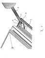
- FIG 1 the corner area of a window sash is shown schematically reproduced, the one of interest here Area is the corner of a rollover bar; analogously can the reinforcement of the corner area and the invention Protection of the miter cut but also in the corner area a glazing bridge.
- the two assembled frame legs are through the miter cut 11 separated and demonstrate inside facing webs 10, the following because of their Arrangement on the outer frame leg area as outer webs be designated; opposite these bridges, and the outer webs 10 parallel, inner webs 9 are arranged.
- the backing component 1 has an end region, the symmetrically the abutting outer webs 10 subordinate, as well as an opposite area, which the Bridges 9 underpinned.
- the deposit component overlaps the miter joint 11 and lies with the tip area 2 under the web 9 on the wall of the groove below on.
- a turning tool for example a Screwdriver
- the hatching on the long sides of the backing component 1 is meant to indicate that these margins are light are bent inwards, so that the deposit component a certain elasticity in the vertical direction is awarded to the level of the deposit component, so that the deposit component by screwing into his End position jammed under the webs 9 and 10.
- this inflection serves to create a Cavity between the backing component and the corner area Miter joint, in through the opening 6 by means of an injection tool 12 adhesive material can be introduced, the on the one hand, the deposit component is permanently fixed and on the other hand, the miter joint 11 seals gas and watertight.
- FIG 2 gives the deposit component according to the invention in detail 1, as used in Figure 1, again.
- the deposit component has two opposing ones Edges 4 on; the end area 5 is for storage formed in the corner of the frame profiles, while the opposite End area 2/3 to underline the opposite webs (s) 9 is formed according to Figure 1.
- the end region 2 is approximately triangular, the straight edge 2a with the center line through the Backing component or with the side edges 4 an angle of 45 °.
- a non-circular opening 6 which on the one hand Engagement for a tool as described in FIG. 1, is formed, and on the other hand for injecting adhesive serves.
- This opening with a bead 7 is preferred surrounded, which facilitates the introduction of the tool and promotes clean working when injecting the adhesive.
- Exemplary dimensions of such a backing component for practical use are: total length about 35 mm, Width in the central area about 14 mm; the space below the center line of the component through the curved Training arises, is about 1 mm high.
- Figure 3 shows another embodiment of the invention Deposit component for use in one Inside corner, for example on the frame.
- the component has a butterfly-like Shape.
- the right-angled notch 13 opposite base line 15 goes to the two wing corners 14 rounded over such that this deposit component via the tool engaging in the non-circular opening 6 according to Figures 3b and 3c in the end position by a rotary-sliding movement can be brought and under the webs and 9 and 10 locked.
- Figure 4 shows an embodiment, in particular is characterized in that the deposit component in the longitudinal direction against a restoring force can be shortened; here is, in the rest, analogous execution to the previously described embodiments, the middle area 16 compressible, for example by an intermediate elastic or resilient element 16, such trained that with a tool over the attachment holes or shoulder knobs 17 of the corner brackets compressed during assembly, introduced and omitted in the corner area so that the angle is at its original length expands and understands the webs 9 and 10.
- Figure 5 shows a further embodiment of the invention Depository component, which in the cases of Is used where the profile has no support web, which the end region 5 of the component can underline, such as this for example for inner corners (for example for Frame or on the glass bridge of wings) is the case.
- the end region 5 is an angled leg 5a formed, for example at an angle of about 90 °, which is supported on an adjacent web 18.
Landscapes
- Engineering & Computer Science (AREA)
- Civil Engineering (AREA)
- Structural Engineering (AREA)
- Joining Of Corner Units Of Frames Or Wings (AREA)
- Body Structure For Vehicles (AREA)
- Glass Compositions (AREA)
- Mechanical Treatment Of Semiconductor (AREA)
- Securing Of Glass Panes Or The Like (AREA)
- Door And Window Frames Mounted To Openings (AREA)
Abstract
Description
Claims (9)
- Hinterlegungsbauteil zur Stabilisierung und Höhenangleichung von aneinander stoßenden Flächen von Rahmenprofilen, dadurch gekennzeichnet, daß sie durch Formgebung und Dimensionierung zum einrastenden oder verriegelnden Unterfassen von sich gegenüberliegenden, im Stoßbereich der Flächen angeordneten Stegen (9/10) ausgebildet sind.
- Hinterlegungsbauteil nach Anspruch 1, dadurch gekennzeichnet, daß er zum Einrasten oder Verriegeln unter den Stegen (9/10) bei gleichzeitger Abdeckung der Gehrungsfuge ausgebildet ist.
- Hinterlegungsbauteil nach Anspruch 1 oder 2, dadurch gekennzeichnet, daß er als flächiges Bauteil ausgebildet ist, dessen einer Endbereich (5) zum Unterfassen des Eckenbereichs der äußeren, aneinander stoßenden Stege (10) des Rahmenprofils ausgebildet ist, wobei der gegenüberliegende Endbereich (2/3) des Winkels zum einrastenden Untergreifen der gegenüberliegenden inneren, aneinander stoßenden Stege (9) des Rahmenprofils ausgebildet ist, und wobei auf dem Hinterlegungsbauteil Mittel (6) zum Ansatz oder Einsatz eines Werkzeugs vorgesehen sind, unter dessen Einwirkung das Hinterlegungsbauteil in die einrastende oder verriegelnde, den Gehrungsschnitt überdeckende Endposition gebracht wird.
- Hinterlegungsbauteil nach Anspruch 3, dadurch gekennzeichnet, daß er zwei sich in Längsrichtung des Hinterlegungsbauteils erstreckende Ränder (4) aufweist, wobei ein erster Rand (4) in einen Spitzenbereich (2) übergeht, der einen geraden Rand (2a) aufweist, der mit dem Randbereich (4) einen Winkel von 45° bildet, wobei der Rand (2a) in einen kreisabschnittsförmigen Bereich (3) übergeht, der wiederum in den zweiten Rand (4) übergeht, und wobei im verjüngten Endbereich (5), der zur Anlage in der Ecke des Rahmenprofils vorgesehen ist, die beiden Ränder (4) kreisabschnittsförmig zusammenlaufen.
- Hinterlegungsbauteil nach Anspruch 4, dadurch gekennzeichnet, daß die sich gegenüberliegenden Seitenbereiche der Ränder (4) leicht nach unten gebogen sind.
- Hinterlegungsbauteil nach Anspruch 5, dadurch gekennzeichnet, daß in der Fläche des Winkels (1) eine unrunde Öffnung (6) zur Einführung eines Drehwerkzeugs ausgebildet ist.
- Hinterlegungsbauteil nach Anspruch 6, dadurch gekennzeichnet, daß die Öffnung (6) von einem Wulst (7) umgeben ist.
- Hinterlegungsbauteil nach Anspruch 3, dadurch gekennzeichnet, daß das Hinterlegungsbauteil in Längsrichtung gegen die Rückstellkraft eines elastischen oder federnden Elements (16) in sich zusammenschiebbar ausgebildet ist, wobei auf der Fläche des Hinterlegungsbauteils Mittel (17) zum Angriff eines Werkzeugs ausgebildet sind, durch die das Hinterlegungsbauteil in Längsrichtung während der Montage zusammendrückbar ist.
- Hinterlegungsbauteil nach einem der vorhergehenden Ansprüche, dadurch gekennzeichnet, daß der Endbereich (5) als angewinkelter Schenkel (5a) ausgebildet ist, der im wesentlich rechtwinklig zur Längsachse des Bauteils verläuft und längenmäßig zum Unterfassen eines benachbarten Profilsteges (18) ausgebildet ist.
Applications Claiming Priority (2)
| Application Number | Priority Date | Filing Date | Title |
|---|---|---|---|
| DE10126278 | 2001-05-29 | ||
| DE10126278A DE10126278C2 (de) | 2001-05-29 | 2001-05-29 | Hinterlegungsbauteil |
Publications (3)
| Publication Number | Publication Date |
|---|---|
| EP1262622A2 true EP1262622A2 (de) | 2002-12-04 |
| EP1262622A3 EP1262622A3 (de) | 2003-11-05 |
| EP1262622B1 EP1262622B1 (de) | 2005-09-28 |
Family
ID=7686610
Family Applications (1)
| Application Number | Title | Priority Date | Filing Date |
|---|---|---|---|
| EP02008949A Expired - Lifetime EP1262622B1 (de) | 2001-05-29 | 2002-04-22 | Hinterlegungsbauteil |
Country Status (4)
| Country | Link |
|---|---|
| EP (1) | EP1262622B1 (de) |
| AT (1) | ATE305560T1 (de) |
| DE (2) | DE10126278C2 (de) |
| ES (1) | ES2249509T3 (de) |
Cited By (2)
| Publication number | Priority date | Publication date | Assignee | Title |
|---|---|---|---|---|
| CN104832049A (zh) * | 2015-04-02 | 2015-08-12 | 佛山市爵豹机械设备有限公司 | 门窗套 |
| FR3041369A1 (fr) * | 2015-09-17 | 2017-03-24 | Atlantem Ind | Cadre mixte de menuiserie et son procede de fabrication |
Families Citing this family (2)
| Publication number | Priority date | Publication date | Assignee | Title |
|---|---|---|---|---|
| DE10217574B3 (de) * | 2002-04-19 | 2004-02-19 | Welser Profile Ag | Bausatz mit Eckverbinder |
| DE202010008917U1 (de) * | 2010-10-28 | 2012-01-30 | SCHÜCO International KG | Rahmenkonstruktion und Einziehwerkzeug |
Family Cites Families (4)
| Publication number | Priority date | Publication date | Assignee | Title |
|---|---|---|---|---|
| DE2226409C3 (de) * | 1972-05-31 | 1980-11-20 | Schueco Heinz Schuermann Gmbh & Co, 4800 Bielefeld | Verbinder für Profile oder Rohre |
| DE2609388C3 (de) * | 1976-03-06 | 1980-02-14 | W. Hartmann & Co (Gmbh & Co), 2000 Hamburg | Stabilisienings- und Ausrichtelement fur Gehrungsstoße zwischen zwei Bauprofilen |
| DE29910478U1 (de) * | 1998-06-19 | 1999-11-11 | W. Hartmann & Co. (GmbH & Co.), 20459 Hamburg | Verbindungselement |
| ITRN990011A1 (it) * | 1999-04-30 | 2000-10-30 | L M Dei F Lli Monticelli S R L | Apparato e metodo per connessione di elementi profilati in condizionedi complanarita' e solidarieta' reciproca, nella fabbricazione di tela |
-
2001
- 2001-05-29 DE DE10126278A patent/DE10126278C2/de not_active Expired - Fee Related
-
2002
- 2002-04-22 ES ES02008949T patent/ES2249509T3/es not_active Expired - Lifetime
- 2002-04-22 AT AT02008949T patent/ATE305560T1/de active
- 2002-04-22 EP EP02008949A patent/EP1262622B1/de not_active Expired - Lifetime
- 2002-04-22 DE DE50204365T patent/DE50204365D1/de not_active Expired - Lifetime
Cited By (2)
| Publication number | Priority date | Publication date | Assignee | Title |
|---|---|---|---|---|
| CN104832049A (zh) * | 2015-04-02 | 2015-08-12 | 佛山市爵豹机械设备有限公司 | 门窗套 |
| FR3041369A1 (fr) * | 2015-09-17 | 2017-03-24 | Atlantem Ind | Cadre mixte de menuiserie et son procede de fabrication |
Also Published As
| Publication number | Publication date |
|---|---|
| DE50204365D1 (de) | 2006-02-09 |
| DE10126278A1 (de) | 2002-12-19 |
| DE10126278C2 (de) | 2003-06-12 |
| EP1262622B1 (de) | 2005-09-28 |
| ES2249509T3 (es) | 2006-04-01 |
| ATE305560T1 (de) | 2005-10-15 |
| EP1262622A3 (de) | 2003-11-05 |
Similar Documents
| Publication | Publication Date | Title |
|---|---|---|
| EP3877610B1 (de) | Paneel | |
| EP2795142B1 (de) | Leimloser korpus | |
| EP2868856B1 (de) | Eckverbinder zum Verbinden auf Gehrung geschnittener Hohlprofile eines Fenster- oder Türrahmens | |
| EP0244734B1 (de) | Rahmen, insbesondere für ein Bild | |
| EP0724061A2 (de) | Verbindungselement | |
| DE69508244T2 (de) | Kreuzverbindung für sprossenelemente | |
| DE19828382C2 (de) | Anordnung zum Befestigen eines einen Hohlquerschnitt aufweisenden Pfostens am Blendrahmen eines Fensters oder einer Türe aus Kunststoff oder Leichtmetall | |
| EP1262622B1 (de) | Hinterlegungsbauteil | |
| EP1580343B1 (de) | Stossverbinder zur Verbindung von Profilen | |
| DE102014102465A1 (de) | Schaltschrank | |
| DE9420809U1 (de) | Gummielastische Profilleiste | |
| DE102007024250A1 (de) | Auszugsprofil für Fensterblende | |
| EP0033877A1 (de) | Fenster oder Tür | |
| DE69403699T2 (de) | Verbindungs- und Verriegelungsvorrichtung zwischen einem Profilträger und einem Sparren oder einem ähnlichen Element | |
| DE4439864C2 (de) | Befestigungsanordnung für tafelförmige Bauelemente | |
| DE69403359T2 (de) | Ausrichteckwinkel für Metallfensterrahmen | |
| DE3245573C2 (de) | Rahmen, insbesondere für eine Duschtrennwand | |
| DE19845138C1 (de) | Spreizkloben mit Verbindungssicherungen | |
| DE3609992C2 (de) | Türzarge zur Ummantelung von Metallzargen | |
| CH420566A (de) | Doppelverglasungsrahmen für Fenster und dgl. | |
| DE69606079T2 (de) | Zusammenbauverfahren für Möbelelemente und Möbel das von diesen Zusammenbau gebildet ist | |
| DE3526729C2 (de) | ||
| DE202019103487U1 (de) | Spreizbarer Eckwinkel | |
| DE4031537A1 (de) | Rahmen fuer tueren | |
| DE2004189A1 (de) | Rahmenprofil mit Einsatzprofil |
Legal Events
| Date | Code | Title | Description |
|---|---|---|---|
| PUAI | Public reference made under article 153(3) epc to a published international application that has entered the european phase |
Free format text: ORIGINAL CODE: 0009012 |
|
| AK | Designated contracting states |
Kind code of ref document: A2 Designated state(s): AT BE CH CY DE DK ES FI FR GB GR IE IT LI LU MC NL PT SE TR |
|
| AX | Request for extension of the european patent |
Free format text: AL;LT;LV;MK;RO;SI |
|
| RAP1 | Party data changed (applicant data changed or rights of an application transferred) |
Owner name: NORSK HYDRO ASA |
|
| PUAL | Search report despatched |
Free format text: ORIGINAL CODE: 0009013 |
|
| AK | Designated contracting states |
Kind code of ref document: A3 Designated state(s): AT BE CH CY DE DK ES FI FR GB GR IE IT LI LU MC NL PT SE TR |
|
| AX | Request for extension of the european patent |
Extension state: AL LT LV MK RO SI |
|
| RIC1 | Information provided on ipc code assigned before grant |
Ipc: 7E 06B 3/964 A Ipc: 7E 06B 3/96 B |
|
| 17P | Request for examination filed |
Effective date: 20031125 |
|
| 17Q | First examination report despatched |
Effective date: 20040209 |
|
| AKX | Designation fees paid |
Designated state(s): AT BE CH CY DE DK ES FI FR GB GR IE IT LI LU MC NL PT SE TR |
|
| GRAP | Despatch of communication of intention to grant a patent |
Free format text: ORIGINAL CODE: EPIDOSNIGR1 |
|
| GRAS | Grant fee paid |
Free format text: ORIGINAL CODE: EPIDOSNIGR3 |
|
| GRAA | (expected) grant |
Free format text: ORIGINAL CODE: 0009210 |
|
| AK | Designated contracting states |
Kind code of ref document: B1 Designated state(s): AT BE CH CY DE DK ES FI FR GB GR IE IT LI LU MC NL PT SE TR |
|
| PG25 | Lapsed in a contracting state [announced via postgrant information from national office to epo] |
Ref country code: FI Free format text: LAPSE BECAUSE OF FAILURE TO SUBMIT A TRANSLATION OF THE DESCRIPTION OR TO PAY THE FEE WITHIN THE PRESCRIBED TIME-LIMIT Effective date: 20050928 |
|
| REG | Reference to a national code |
Ref country code: GB Ref legal event code: FG4D Free format text: NOT ENGLISH |
|
| REG | Reference to a national code |
Ref country code: CH Ref legal event code: EP |
|
| REG | Reference to a national code |
Ref country code: IE Ref legal event code: FG4D Free format text: LANGUAGE OF EP DOCUMENT: GERMAN |
|
| GBT | Gb: translation of ep patent filed (gb section 77(6)(a)/1977) |
Effective date: 20051129 |
|
| PG25 | Lapsed in a contracting state [announced via postgrant information from national office to epo] |
Ref country code: DK Free format text: LAPSE BECAUSE OF FAILURE TO SUBMIT A TRANSLATION OF THE DESCRIPTION OR TO PAY THE FEE WITHIN THE PRESCRIBED TIME-LIMIT Effective date: 20051228 Ref country code: GR Free format text: LAPSE BECAUSE OF FAILURE TO SUBMIT A TRANSLATION OF THE DESCRIPTION OR TO PAY THE FEE WITHIN THE PRESCRIBED TIME-LIMIT Effective date: 20051228 |
|
| REG | Reference to a national code |
Ref country code: CH Ref legal event code: NV Representative=s name: E. BLUM & CO. PATENTANWAELTE |
|
| REG | Reference to a national code |
Ref country code: SE Ref legal event code: TRGR |
|
| REF | Corresponds to: |
Ref document number: 50204365 Country of ref document: DE Date of ref document: 20060209 Kind code of ref document: P |
|
| REG | Reference to a national code |
Ref country code: ES Ref legal event code: FG2A Ref document number: 2249509 Country of ref document: ES Kind code of ref document: T3 |
|
| PG25 | Lapsed in a contracting state [announced via postgrant information from national office to epo] |
Ref country code: MC Free format text: LAPSE BECAUSE OF NON-PAYMENT OF DUE FEES Effective date: 20060430 |
|
| ET | Fr: translation filed | ||
| PLBE | No opposition filed within time limit |
Free format text: ORIGINAL CODE: 0009261 |
|
| STAA | Information on the status of an ep patent application or granted ep patent |
Free format text: STATUS: NO OPPOSITION FILED WITHIN TIME LIMIT |
|
| 26N | No opposition filed |
Effective date: 20060629 |
|
| REG | Reference to a national code |
Ref country code: CH Ref legal event code: PFA Owner name: NORSK HYDRO ASA Free format text: NORSK HYDRO ASA#BYGDOY ALLE 2#0257 OSLO 2 (NO) -TRANSFER TO- NORSK HYDRO ASA#BYGDOY ALLE 2#0257 OSLO 2 (NO) |
|
| PG25 | Lapsed in a contracting state [announced via postgrant information from national office to epo] |
Ref country code: LU Free format text: LAPSE BECAUSE OF NON-PAYMENT OF DUE FEES Effective date: 20060422 Ref country code: TR Free format text: LAPSE BECAUSE OF FAILURE TO SUBMIT A TRANSLATION OF THE DESCRIPTION OR TO PAY THE FEE WITHIN THE PRESCRIBED TIME-LIMIT Effective date: 20050928 |
|
| PG25 | Lapsed in a contracting state [announced via postgrant information from national office to epo] |
Ref country code: CY Free format text: LAPSE BECAUSE OF FAILURE TO SUBMIT A TRANSLATION OF THE DESCRIPTION OR TO PAY THE FEE WITHIN THE PRESCRIBED TIME-LIMIT Effective date: 20050928 |
|
| PGFP | Annual fee paid to national office [announced via postgrant information from national office to epo] |
Ref country code: PT Payment date: 20100416 Year of fee payment: 9 |
|
| PGFP | Annual fee paid to national office [announced via postgrant information from national office to epo] |
Ref country code: SE Payment date: 20110414 Year of fee payment: 10 Ref country code: ES Payment date: 20110426 Year of fee payment: 10 Ref country code: IE Payment date: 20110426 Year of fee payment: 10 Ref country code: FR Payment date: 20110510 Year of fee payment: 10 |
|
| PGFP | Annual fee paid to national office [announced via postgrant information from national office to epo] |
Ref country code: GB Payment date: 20110421 Year of fee payment: 10 Ref country code: AT Payment date: 20110414 Year of fee payment: 10 Ref country code: NL Payment date: 20110426 Year of fee payment: 10 |
|
| PGFP | Annual fee paid to national office [announced via postgrant information from national office to epo] |
Ref country code: IT Payment date: 20110421 Year of fee payment: 10 |
|
| REG | Reference to a national code |
Ref country code: PT Ref legal event code: MM4A Free format text: LAPSE DUE TO NON-PAYMENT OF FEES Effective date: 20111024 |
|
| PG25 | Lapsed in a contracting state [announced via postgrant information from national office to epo] |
Ref country code: PT Free format text: LAPSE BECAUSE OF NON-PAYMENT OF DUE FEES Effective date: 20111024 |
|
| REG | Reference to a national code |
Ref country code: NL Ref legal event code: V1 Effective date: 20121101 |
|
| REG | Reference to a national code |
Ref country code: SE Ref legal event code: EUG |
|
| REG | Reference to a national code |
Ref country code: AT Ref legal event code: MM01 Ref document number: 305560 Country of ref document: AT Kind code of ref document: T Effective date: 20120422 |
|
| GBPC | Gb: european patent ceased through non-payment of renewal fee |
Effective date: 20120422 |
|
| REG | Reference to a national code |
Ref country code: IE Ref legal event code: MM4A |
|
| REG | Reference to a national code |
Ref country code: FR Ref legal event code: ST Effective date: 20121228 |
|
| PG25 | Lapsed in a contracting state [announced via postgrant information from national office to epo] |
Ref country code: IE Free format text: LAPSE BECAUSE OF NON-PAYMENT OF DUE FEES Effective date: 20120422 Ref country code: AT Free format text: LAPSE BECAUSE OF NON-PAYMENT OF DUE FEES Effective date: 20120422 Ref country code: GB Free format text: LAPSE BECAUSE OF NON-PAYMENT OF DUE FEES Effective date: 20120422 |
|
| PG25 | Lapsed in a contracting state [announced via postgrant information from national office to epo] |
Ref country code: SE Free format text: LAPSE BECAUSE OF NON-PAYMENT OF DUE FEES Effective date: 20120423 Ref country code: IT Free format text: LAPSE BECAUSE OF NON-PAYMENT OF DUE FEES Effective date: 20120422 Ref country code: FR Free format text: LAPSE BECAUSE OF NON-PAYMENT OF DUE FEES Effective date: 20120430 |
|
| PG25 | Lapsed in a contracting state [announced via postgrant information from national office to epo] |
Ref country code: NL Free format text: LAPSE BECAUSE OF NON-PAYMENT OF DUE FEES Effective date: 20121101 |
|
| REG | Reference to a national code |
Ref country code: ES Ref legal event code: FD2A Effective date: 20131030 |
|
| PG25 | Lapsed in a contracting state [announced via postgrant information from national office to epo] |
Ref country code: ES Free format text: LAPSE BECAUSE OF NON-PAYMENT OF DUE FEES Effective date: 20120423 |
|
| REG | Reference to a national code |
Ref country code: DE Ref legal event code: R082 Ref document number: 50204365 Country of ref document: DE Representative=s name: KOTITSCHKE & HEURUNG PARTNERSCHAFT MBB PATENT-, DE |
|
| PGFP | Annual fee paid to national office [announced via postgrant information from national office to epo] |
Ref country code: CH Payment date: 20140418 Year of fee payment: 13 |
|
| REG | Reference to a national code |
Ref country code: CH Ref legal event code: PUE Owner name: SAPA AS, NO Free format text: FORMER OWNER: NORSK HYDRO ASA, NO |
|
| REG | Reference to a national code |
Ref country code: DE Ref legal event code: R082 Ref document number: 50204365 Country of ref document: DE Representative=s name: KOTITSCHKE & HEURUNG PARTNERSCHAFT MBB PATENT-, DE |
|
| REG | Reference to a national code |
Ref country code: DE Ref legal event code: R082 Ref document number: 50204365 Country of ref document: DE Effective date: 20140109 Ref country code: DE Ref legal event code: R082 Ref document number: 50204365 Country of ref document: DE Representative=s name: KOTITSCHKE & HEURUNG PARTNERSCHAFT MBB PATENT-, DE Effective date: 20141017 Ref country code: DE Ref legal event code: R082 Ref document number: 50204365 Country of ref document: DE Representative=s name: KOTITSCHKE & HEURUNG PARTNERSCHAFT MBB PATENT-, DE Effective date: 20140109 Ref country code: DE Ref legal event code: R081 Ref document number: 50204365 Country of ref document: DE Owner name: SAPA AS, NO Free format text: FORMER OWNER: NORSK HYDRO ASA, OSLO, NO Effective date: 20141017 |
|
| REG | Reference to a national code |
Ref country code: DE Ref legal event code: R082 Ref document number: 50204365 Country of ref document: DE |
|
| REG | Reference to a national code |
Ref country code: CH Ref legal event code: PL |
|
| PG25 | Lapsed in a contracting state [announced via postgrant information from national office to epo] |
Ref country code: CH Free format text: LAPSE BECAUSE OF NON-PAYMENT OF DUE FEES Effective date: 20150430 Ref country code: LI Free format text: LAPSE BECAUSE OF NON-PAYMENT OF DUE FEES Effective date: 20150430 |
|
| PGFP | Annual fee paid to national office [announced via postgrant information from national office to epo] |
Ref country code: DE Payment date: 20210420 Year of fee payment: 20 |
|
| PGFP | Annual fee paid to national office [announced via postgrant information from national office to epo] |
Ref country code: BE Payment date: 20210420 Year of fee payment: 20 |
|
| REG | Reference to a national code |
Ref country code: DE Ref legal event code: R082 Ref document number: 50204365 Country of ref document: DE Representative=s name: EISENFUEHR SPEISER PATENTANWAELTE RECHTSANWAEL, DE |
|
| REG | Reference to a national code |
Ref country code: DE Ref legal event code: R071 Ref document number: 50204365 Country of ref document: DE |
|
| REG | Reference to a national code |
Ref country code: BE Ref legal event code: MK Effective date: 20220422 |