EP1262373A2 - Plate provided with an electrically activated light emitting foil - Google Patents
Plate provided with an electrically activated light emitting foil Download PDFInfo
- Publication number
- EP1262373A2 EP1262373A2 EP02010972A EP02010972A EP1262373A2 EP 1262373 A2 EP1262373 A2 EP 1262373A2 EP 02010972 A EP02010972 A EP 02010972A EP 02010972 A EP02010972 A EP 02010972A EP 1262373 A2 EP1262373 A2 EP 1262373A2
- Authority
- EP
- European Patent Office
- Prior art keywords
- film
- sign according
- lens
- symbol carrier
- retroreflective
- Prior art date
- Legal status (The legal status is an assumption and is not a legal conclusion. Google has not performed a legal analysis and makes no representation as to the accuracy of the status listed.)
- Withdrawn
Links
- 239000011888 foil Substances 0.000 title claims abstract description 14
- NMFHJNAPXOMSRX-PUPDPRJKSA-N [(1r)-3-(3,4-dimethoxyphenyl)-1-[3-(2-morpholin-4-ylethoxy)phenyl]propyl] (2s)-1-[(2s)-2-(3,4,5-trimethoxyphenyl)butanoyl]piperidine-2-carboxylate Chemical compound C([C@@H](OC(=O)[C@@H]1CCCCN1C(=O)[C@@H](CC)C=1C=C(OC)C(OC)=C(OC)C=1)C=1C=C(OCCN2CCOCC2)C=CC=1)CC1=CC=C(OC)C(OC)=C1 NMFHJNAPXOMSRX-PUPDPRJKSA-N 0.000 description 2
- 230000000694 effects Effects 0.000 description 2
- 230000003287 optical effect Effects 0.000 description 2
- 230000002411 adverse Effects 0.000 description 1
- 230000005540 biological transmission Effects 0.000 description 1
- 230000015572 biosynthetic process Effects 0.000 description 1
- 239000011248 coating agent Substances 0.000 description 1
- 238000000576 coating method Methods 0.000 description 1
- 238000005755 formation reaction Methods 0.000 description 1
- 238000009413 insulation Methods 0.000 description 1
- 230000002093 peripheral effect Effects 0.000 description 1
- 239000004033 plastic Substances 0.000 description 1
- 239000002985 plastic film Substances 0.000 description 1
- 238000007363 ring formation reaction Methods 0.000 description 1
Images
Classifications
-
- H—ELECTRICITY
- H10—SEMICONDUCTOR DEVICES; ELECTRIC SOLID-STATE DEVICES NOT OTHERWISE PROVIDED FOR
- H10K—ORGANIC ELECTRIC SOLID-STATE DEVICES
- H10K50/00—Organic light-emitting devices
- H10K50/80—Constructional details
- H10K50/85—Arrangements for extracting light from the devices
- H10K50/856—Arrangements for extracting light from the devices comprising reflective means
-
- B—PERFORMING OPERATIONS; TRANSPORTING
- B60—VEHICLES IN GENERAL
- B60R—VEHICLES, VEHICLE FITTINGS, OR VEHICLE PARTS, NOT OTHERWISE PROVIDED FOR
- B60R13/00—Elements for body-finishing, identifying, or decorating; Arrangements or adaptations for advertising purposes
- B60R13/10—Registration, licensing, or like devices
-
- G—PHYSICS
- G09—EDUCATION; CRYPTOGRAPHY; DISPLAY; ADVERTISING; SEALS
- G09F—DISPLAYING; ADVERTISING; SIGNS; LABELS OR NAME-PLATES; SEALS
- G09F13/00—Illuminated signs; Luminous advertising
- G09F13/04—Signs, boards or panels, illuminated from behind the insignia
-
- G—PHYSICS
- G09—EDUCATION; CRYPTOGRAPHY; DISPLAY; ADVERTISING; SEALS
- G09F—DISPLAYING; ADVERTISING; SIGNS; LABELS OR NAME-PLATES; SEALS
- G09F13/00—Illuminated signs; Luminous advertising
- G09F13/20—Illuminated signs; Luminous advertising with luminescent surfaces or parts
- G09F13/22—Illuminated signs; Luminous advertising with luminescent surfaces or parts electroluminescent
-
- H—ELECTRICITY
- H10—SEMICONDUCTOR DEVICES; ELECTRIC SOLID-STATE DEVICES NOT OTHERWISE PROVIDED FOR
- H10K—ORGANIC ELECTRIC SOLID-STATE DEVICES
- H10K59/00—Integrated devices, or assemblies of multiple devices, comprising at least one organic light-emitting element covered by group H10K50/00
- H10K59/10—OLED displays
- H10K59/221—Static displays, e.g. displaying permanent logos
-
- H—ELECTRICITY
- H10—SEMICONDUCTOR DEVICES; ELECTRIC SOLID-STATE DEVICES NOT OTHERWISE PROVIDED FOR
- H10K—ORGANIC ELECTRIC SOLID-STATE DEVICES
- H10K59/00—Integrated devices, or assemblies of multiple devices, comprising at least one organic light-emitting element covered by group H10K50/00
- H10K59/80—Constructional details
- H10K59/875—Arrangements for extracting light from the devices
- H10K59/878—Arrangements for extracting light from the devices comprising reflective means
Definitions
- the invention relates to a plate, in particular a motor vehicle license plate the type mentioned in the preamble of claim 1.
- the Symbol carrier formed by a rigid plastic plate, which in the as a holding frame trained housing in front of an electroluminescent film, electrically activated luminous film is arranged.
- the from the holding frame enclosed light passage opening through which the electrical activatable luminescent film emitted light to the outside when switched on occurs after it has illuminated the symbol carrier from behind is not further closed because the symbol carrier because of its rigidity from the above Edge of the housing can be held safely and easily this also fixes the electrically activatable light film behind it.
- This known arrangement is advantageous in that it can be activated electrically Luminous film directly illuminates the background of the marking is achieved without the need for separately arranged lighting is.
- the well-known license plate is extremely compact and space-saving.
- the invention is therefore based on the object of a shield of the type mentioned Kind in such a way that it is in addition to that with the help of an electrical activatable luminescent film self-lighting also retroreflective Has properties.
- the invention provides that summarized in claim 1 Characteristics before.
- This rough layer can be realized in different ways. At a particularly preferred embodiment is between the retroreflective Foil and the lens another rough foil arranged on both sides, which in both directions has a very high transparency and prevents that the retroreflective sheeting, which can then have a completely smooth surface, so close to the also smooth inner surface of the lens that the optical disturbances mentioned above arise.
- the film according to the invention rough layer due to a rough coating either of the outward facing Surface of the retroreflective sheeting and / or the inward facing one To create the surface of the lens.
- a particular advantage of the shield according to the invention can be seen in the fact that a separate symbol carrier is no longer absolutely necessary. Much more the symbols to be displayed on the sign can be placed on any of the viewer's seen in front of the back surface of the retroreflective sheeting Surfaces, i.e. on the front of the retroreflective sheeting, the Back or front of the rough film on both sides or the back or
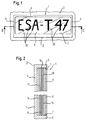
- the shield 1 has a housing 3 with a rear wall 4, one around the entire circumference of the rear wall revolving, forward, i.e. towards the viewer (in Fig. 2 after right) extending edge 5, which is integrally connected to the rear wall 4 can be.
- the forward projecting edge 5 encloses a light transmission opening 7, the is closed by a transparent lens 9.
- the lens 9 can attached to the peripheral edge 5 of the housing 3 in any suitable manner his.
- the film on the far left is an electrically activatable luminescent film 14, which is connected to a electrical energy source is connected so that with the help of a switch electrical voltage can be applied to them. It is either from one Electroluminescent film or preferably formed from an OLED film. in the activated state, the entire film 14 lights up evenly and that of it outgoing light penetrates the films arranged to the right of it in FIG. 2 15 and 16 and the lens 9, so that in the direction of Fig. 1, the entire Light passage opening 7 appears brightly lit from behind.
- the retroreflective sheeting 15 Before, i.e. in FIG. 2 to the right of the electrically activatable luminous film 14 is one retroreflective sheeting 15 arranged so that its retroreflective side or face to the right and from the outside through the lens 9 and Film 16 retroreflected so that it strikes it Reverses path and through the film 16 and the lens 9 approximately in the in the same direction in which it entered.
- the retroreflective Film 15 at least partially transparent, so that a significant part of the from the electrically activatable luminous film 14 in the direction of the light passage opening 7 emitted light can pass through it.
- a further film 16 is arranged, which is a light on its two flat sides roughened layer.
- This film 16 is very highly transparent, that both the light coming from the inside of the electrically activatable luminescent film 14 as well as external light coming from outside, both in front of and to the front be attached to the lens. It is not necessary that all symbols to be displayed are on the same surface.
- the films between the rear wall and the Lenses lie loosely on top of each other and from the rear wall and the lens are held so that no additional fasteners are required are.
- any other films can also be used come which have the required optical properties, i.e. a have the highest possible transparency.
- the film in question is important that it comes from outside light regardless of the angle of incidence to a very high degree in the respective direction of incidence reflected.
- the electrically activatable luminescent film can be an electroluminescent film act that are controlled in a known manner with an AC voltage is that in a motor vehicle license plate with the help of a ballast can be generated from the on-board DC voltage.
- a foil is particularly preferred as the electrically activatable luminous foil with organic light-emitting diodes, a so-called.
- OLED film to use the is that they are characterized by an extremely simple additional circuit a DC voltage that can be derived from on-board DC voltage can be operated.
- the control electronics required for electroluminescent films is also dispensed with like special insulation measures.
- Another advantage of OLED films is the much higher luminance that can be achieved.
- this is a license plate of a motor vehicle designed shield 1 on the body panel 2 of a motor vehicle attached in a manner not shown. ner reflection on the retroreflective film 15 without significant loss of intensity can pass through it.
- this further film 16 prevents it from closing a local suction or application effect between the retroreflective sheeting 15 and the inside of the lens 9 can come. Without the presence the further film 16, these effects for the formation of local would be clear delineated dark spots or Newton rings that result when viewed of the shield would be clearly visible from the outside and the appearance would adversely affect the shield.
- Symbols 20 can be on the front and / or back of a symbol carrier are and differ in their transparency from the other areas of the symbol carrier. In the present case they are practically opaque, so that they are almost compared to the completely translucent remaining areas of the symbol carrier appear black.
- the symbol carrier just mentioned is not necessarily an additional component. Rather, the symbols to be displayed can the front of the retroreflective sheeting 15 or the front or back be printed on the further film 16. It is also possible to use the symbols 20 to be provided on the inner or outer surface of the lens 9. There you can also as sublime, i.e. structures protruding from the flat side in question be formed.
- FIG. 2 additional symbol carrier, which is designed as a flat disc or film is to be placed in front of the retroreflective sheeting 15.
- the symbol carrier can also have more than two levels of transparency. Also can or more of the foils or the outer or inner surface of the lens 9 in different areas may be colored differently, so that there are more Design options result, which in particular also Allow use of a sign according to the invention as a traffic sign.
Landscapes
- Engineering & Computer Science (AREA)
- Physics & Mathematics (AREA)
- General Physics & Mathematics (AREA)
- Theoretical Computer Science (AREA)
- Mechanical Engineering (AREA)
- Optics & Photonics (AREA)
- Illuminated Signs And Luminous Advertising (AREA)
- Vehicle Waterproofing, Decoration, And Sanitation Devices (AREA)
Abstract
Description
Die Erfindung betrifft ein Schild, insbesondere ein Kraftfahrzeug-Kennzeichenschild der im Oberbegriff von Anspruch 1 genannten Art.The invention relates to a plate, in particular a motor vehicle license plate the type mentioned in the preamble of claim 1.
Bei einem unter diesen Oberbegriff fallenden Kraftfahrzeug-Kennzeichenschild, wie es aus dem deutschen Gebrauchsmuster 297 12 954.6 bekannt ist, wird der Symbolträger von einer steifen Kunststoffplatte gebildet, welche in dem als Halterahmen ausgebildeten Gehäuse vor einer als Elektrolumineszenzfolie ausgebildeten, elektrisch aktivierbaren Leuchtfolie angeordnet ist. Die vom Halterahmen umschlossene Lichtdurchtrittsöffnung, durch welche das von der elektrisch aktivierbaren Leuchtfolie im eingeschalteten Zustand abgegebene Licht nach außen tritt, nachdem es den Symbolträger von hinten her durchleuchtet hat, ist nicht weiter verschlossen, da der Symbolträger wegen seiner Steifigkeit von dem vorstehenden Rand des Gehäuses ohne weiteres sicher gehalten werden kann und dadurch auch die hinter ihm liegende elektrisch aktivierbare Leuchtfolie fixiert.In the case of a motor vehicle license plate falling under this generic term, as is known from German utility model 297 12 954.6, the Symbol carrier formed by a rigid plastic plate, which in the as a holding frame trained housing in front of an electroluminescent film, electrically activated luminous film is arranged. The from the holding frame enclosed light passage opening through which the electrical activatable luminescent film emitted light to the outside when switched on occurs after it has illuminated the symbol carrier from behind is not further closed because the symbol carrier because of its rigidity from the above Edge of the housing can be held safely and easily this also fixes the electrically activatable light film behind it.
Diese bekannte Anordnung ist insofern vorteilhaft, als durch die elektrisch aktivierbare Leuchtfolie eine direkte Beleuchtung des Hintergrundes der Kennzeichnung erzielt wird, ohne daß eine separat angeordnete Beleuchtung erforderlich ist. Somit ist das bekannte Kennzeichenschild äußerst kompakt und platzsparend.This known arrangement is advantageous in that it can be activated electrically Luminous film directly illuminates the background of the marking is achieved without the need for separately arranged lighting is. The well-known license plate is extremely compact and space-saving.
Nachteilig ist, daß keine steifen, d.h. als Verschluß der Lichtdurchtrittsöffnung geeigneten Kunststoffplatten zur Verfügung stehen, die nicht nur für das von der elektrisch aktivierbaren Leuchtfolie abgegebene, von hinten kommende Licht transparent sondern gleichzeitig für von außen kommendes, auf den Symbolträger auffallendes Fremdlicht retroreflektierend sind, wie dies vom Gesetzgeber insbesondere für Kraftfahrzeug-Kennzeichenschilder verlangt wird, aber auch für andere Schilder, beispielsweise Verkehrsschilder von Vorteil bzw. oder erforderlich ist.The disadvantage is that none are stiff, i.e. as a closure of the light passage opening Suitable plastic sheets are available, not only for the Electrically activated luminescent film emitted light coming from behind transparent but at the same time for the symbol carrier coming from outside striking external light is retroreflective, as is the case with the legislature is required in particular for motor vehicle license plates, but also for other signs, for example traffic signs advantageous or or required is.
Somit liegt der Erfindung die Aufgabe zugrunde, ein Schild der eingangs genannten Art so weiterzubilden, daß es zusätzlich zu der mit Hilfe einer elektrisch aktivierbaren Leuchtfolie erfolgenden Eigenbeleuchtung auch retroreflektierende Eigenschaften aufweist.The invention is therefore based on the object of a shield of the type mentioned Kind in such a way that it is in addition to that with the help of an electrical activatable luminescent film self-lighting also retroreflective Has properties.
Zur Lösung dieser Aufgabe sieht die Erfindung die im Anspruch 1 zusammengefaßten Merkmale vor. To achieve this object, the invention provides that summarized in claim 1 Characteristics before.
Ausgangspunkt dieser Lösung ist die Tatsache, daß auf dem Markt Kunststorfolien zur Verfügung stehen (beispielsweise die unter der Handelsmarke 3M Scotchlite von 3M angebotene Folie), die für Licht, das auf ihre Rückseite auftrifft, weitgehend transparent sind, während sie auf ihre Vorderseite auffallendes Licht retroreflektieren. Da diese Folien aber keine Eigensteifigkeit besitzen, können sie nicht in der Weise, wie dies aus dem Stand der Technik bekannt ist, als "Verschluß-Platte" der Lichtaustrittsöffnung des Schildgehäuses dienen, wie dies bei dem Symbolträger des oben diskutierten deutschen Gebrauchsmuster 297 12 954.6 der Fall ist.The starting point of this solution is the fact that there are artificial gate films on the market are available (for example, under the 3M trademark Scotchlite film offered by 3M) which is used for light hitting its back are largely transparent as they shine light on their front retroreflecting. However, since these foils have no inherent rigidity, they can not as known in the art as "Locking plate" of the light exit opening of the shield housing serve like this for the symbol carrier of the German utility model 297 12 discussed above 954.6 is the case.
Um die elektrisch aktivierbare Leuchtfolie und die vor ihr angeordnete retroreflektierende Folie in ihrer flachen Anlage an der Gehäuserückwand zu stabilisieren, ist es daher erforderlich, die Lichtdurchtrittsöffnung durch eine Lichtscheibe zu verschließen, die für Licht in beiden Richtungen transparent ist und somit primär eine mechanische Haltefunktion erfüllt.Around the electrically activatable luminous film and the retroreflective one arranged in front of it Stabilize the film in its flat system on the rear wall of the housing it is therefore necessary to close the light passage opening through a lens seal that is transparent to light in both directions and therefore primary fulfills a mechanical holding function.
Ohne weitere Maßnahmen ergibt sich dabei aber das Problem, daß sich die retroreflektierende Folie in ihrer flächigen Anlage an die Innenseite der Lichtscheibe über den gesamten Flächenbereich ungleichmäßig dicht anlegt und teilweise sogar ansaugt, so daß auch bei gleichmäßiger Beleuchtung von innen oder außen unterschiedlich helle bzw. dunkle Zonen bzw. Newton-Ringbildungen entstehen. Dies ist nicht nur unschön sondern insbesondere bei Kraftfahrzeug-Kennzeichenschildern unzulässig. Zur Behebung dieser Schwierigkeiten ist gemäß der Erfindung vorgesehen, zwischen der Innenseite der Lichtscheibe und der ihr zugewandten Oberfläche der retroreflektierenden Folie eine rauhe Schicht vorzusehen.Without further measures, the problem arises that the retroreflective Foil in its flat system on the inside of the lens non-uniformly dense across the entire surface area and partially even sucks in, so that even with uniform lighting from the inside or outside differently bright or dark zones or Newton ring formations arise. This is not only unsightly, but particularly in the case of motor vehicle license plates inadmissible. To resolve these difficulties is according to the invention provided between the inside of the lens and a rough layer on the surface of the retroreflective film facing it provided.
Diese rauhe Schicht kann auf unterschiedliche Weise realisiert werden. Bei einer besonders bevorzugten Ausführungsform ist zwischen der retroreflektierenden Folie und der Lichtscheibe eine weitere, beidseitig rauhe Folie angeordnet, die in beiden Richtungen eine sehr hohe Transparenz besitzt und verhindert, daß sich die retroreflektierende Folie, die dann eine völlig glatte Oberfläche besitzen kann, an die ebenfalls glatte Innenfläche der Lichtscheibe so eng anlegen kann, daß die oben erwähnten optischen Störungen entstehen.This rough layer can be realized in different ways. At a particularly preferred embodiment is between the retroreflective Foil and the lens another rough foil arranged on both sides, which in both directions has a very high transparency and prevents that the retroreflective sheeting, which can then have a completely smooth surface, so close to the also smooth inner surface of the lens that the optical disturbances mentioned above arise.
Alternativ zu dieser zusätzlichen Folie ist es auch möglich, die erfindungsgemäße rauhe Schicht durch eine rauhe Beschichtung entweder der nach außen weisenden Fläche der retroreflektierenden Folie und/oder der nach innen weisenden Oberfläche der Lichtscheibe zu schaffen.As an alternative to this additional film, it is also possible to use the film according to the invention rough layer due to a rough coating either of the outward facing Surface of the retroreflective sheeting and / or the inward facing one To create the surface of the lens.
Ein besonderer Vorteil des erfindungsgemäßen Schildes ist darin zu sehen, daß ein gesonderter Symbolträger nicht mehr zwingend erforderlich ist. Vielmehr können die auf dem Schild darzustellenden Symbole auf jeder der vom Betrachter her gesehen vor der hinteren Oberfläche der retroreflektierenden Folie liegenden Oberflächen, d.h. auf der Vorderseite der retroreflektierenden Folie, der Rück- bzw. Vorderseite der auf beiden Seiten rauhen Folie oder der Rück- bzw. A particular advantage of the shield according to the invention can be seen in the fact that a separate symbol carrier is no longer absolutely necessary. Much more the symbols to be displayed on the sign can be placed on any of the viewer's seen in front of the back surface of the retroreflective sheeting Surfaces, i.e. on the front of the retroreflective sheeting, the Back or front of the rough film on both sides or the back or
Wie man insbesondere der Fig. 2 entnehmen kann, besitzt das Schild 1 ein Gehäuse
3 mit einer Rückwand 4, die einen um den gesamten Umfang der Rückwand
umlaufenden, sich nach vorne, d.h. zum Betrachter hin (in Fig. 2 nach
rechts) erstreckenden Rand 5 trägt, der mit der Rückwand 4 einstückig verbunden
sein kann.As can be seen in particular from FIG. 2, the shield 1 has a
Der nach vorne vorstehende Rand 5 umschließt eine Lichtdurchlaßöffnung 7, die
durch eine transparente Lichtscheibe 9 verschlossen ist. Die Lichtscheibe 9 kann
auf irgendeine geeignete Weise am umlaufenden Rand 5 des Gehäuses 3 befestigt
sein.The forward projecting
Zwischen der transparenten Lichtscheibe 9 und der Rückwand 4 des Gehäuses 3
befinden sich drei beim vorliegenden Ausführungsbeispiel in etwa die gleiche
Fläche wie die Rückwand 4 besitzende Folien 14, 15, 16, die mit ihren Flachseiten
aneinander sowie an der Innenfläche der Lichtscheibe 9 und der Innenfläche
der Rückwand 4 anliegen. Die in Fig. 2 wiedergegebenen Abstände zwischen
den Folien und den Gehäuseteilen 4 und 9 dienen lediglich der Veranschaulichung
und sind in Wirklichkeit verschwindend klein.Between the
Bei der hintersten, d.h. in Fig. 2 ganz links befindlichen Folie handelt es sich um
eine elektrisch aktivierbare Leuchtfolie 14, die in nicht dargestellter Weise an eine
elektrische Energiequelle so angeschlossen ist, daß mit Hilfe eines Schalters
elektrische Spannung an sie angelegt werden kann. Sie wird entweder von einer
Elektrolumineszenzfolie oder vorzugsweise von einer OLED-Folie gebildet. Im
aktivierten Zustand leuchtet die gesamte Folie 14 gleichmäßig und das von ihr
ausgehende Licht durchdringt die in Fig. 2 rechts neben ihr angeordneten Folien
15 und 16 sowie die Lichtscheibe 9, so daß in Blickrichtung der Fig. 1 die gesamte
Lichtdurchtrittsöffnung 7 von hinten her hell erleuchtet erscheint.At the rear, i.e. in FIG. 2 the film on the far left is
an electrically activatable
Vor, d.h. in Fig. 2 rechts neben der elektrisch aktivierbaren Leuchtfolie 14 ist eine
retroreflektierende Folie 15 so angeordnet, daß ihre retroreflektierende Seite
bzw. Fläche nach rechts weist und von außen durch die Lichtscheibe 9 und die
Folie 16 hindurch auf sie auffallendes Fremdlicht so retroreflektiert, daß es seinen
Weg umkehrt und durch die Folie 16 und die Lichtscheibe 9 in etwa in der
gleichen Richtung austritt, in der es eingetreten ist. Zusätzlich ist die retroreflektierende
Folie 15 zumindest teilweise transparent, so daß ein erheblicher Teil des
von der elektrisch aktivierbaren Leuchtfolie 14 in Richtung der Lichtdurchtrittsöffnung
7 ausgesandten Lichts durch sie hindurchtreten kann.Before, i.e. in FIG. 2 to the right of the electrically activatable
Zwischen der retroreflektierenden Folie 15 und der Innenseite der Lichtscheibe 9
ist eine-weitere Folie 16 angeordnet, die auf ihren beiden Flachseiten eine leicht
aufgerauhte Schicht trägt. Diese Folie 16 ist in sehr hohem Maße transparent,
daß sowohl das von Innen kommende Licht der elektrisch aktivierbaren Leuchtfolie
14 als auch von außen kommendes Fremdlicht, sowohl vor als auch nach sei-Vorderseite
der Lichtscheibe angebracht werden. Dabei ist es nicht erforderlich,
daß sich alle darzustellenden Symbole auf der gleichen Oberfläche befinden.Between the
Besonders bevorzugt ist es, diese Symbole auf einer oder mehreren der Folienoberflächen anzubringen, da diese sehr einfach bedruckt werden können.It is particularly preferred to have these symbols on one or more of the film surfaces to attach because they can be printed very easily.
Vorteilhaft ist ebenfalls, daß die Folien zwischen der Gehäuserückwand und der Lichtscheibe lose aufeinander liegen und von der Rückwand und der Lichtscheibe gehalten werden, so daß keine zusätzlichen Befestigungsmittel erforderlich sind.It is also advantageous that the films between the rear wall and the Lenses lie loosely on top of each other and from the rear wall and the lens are held so that no additional fasteners are required are.
Neben den erwähnten Folien können auch beliebige andere Folien zum Einsatz kommen, welche die erforderlichen optischen Eigenschaften aufweisen, d.h. eine möglichst hohe Transparenz besitzen. Bei der retroreflektierenden Oberfläche der betreffenden Folie ist von Bedeutung, daß sie von außen kommendes Licht unabhängig vom Einfallswinkel in sehr hohem Maße in der jeweiligen Einfallsrichtung reflektiert.In addition to the films mentioned, any other films can also be used come which have the required optical properties, i.e. a have the highest possible transparency. With the retroreflective surface The film in question is important that it comes from outside light regardless of the angle of incidence to a very high degree in the respective direction of incidence reflected.
Bei der elektrisch aktivierbaren Leuchtfolie kann es sich um eine Elektrolumineszenzfolie handeln, die in bekannter Weise mit eine Wechselspannung angesteuert wird, die bei einem Kraftfahrzeugkennzeichenschild mit Hilfe eine Vorschaltgerätes aus der Bord-Gleichspannung erzeugt werden Ikann.The electrically activatable luminescent film can be an electroluminescent film act that are controlled in a known manner with an AC voltage is that in a motor vehicle license plate with the help of a ballast can be generated from the on-board DC voltage.
Besonder bevorzugt ist jedoch, als elektrisch aktivierbare Leuchtfolie eine Folie mit organischen Leuchtdioden, eine sog. OLED-Folie zu verwenden, die den Vorteil bietet, daß sie mit einer durch eine äußerst einfache Zusatzschaltung aus einer Bord-Gleichspannung ableitbaren Gleichspannung betrieben werden kann. Die für Elektrolumineszenzfolien erfoderliche Ansteuerelektronik entfällt ebenso wie besondere Isolationsmaßnahmen. Ein weiterer Vorteil von OLED-Folien ist die wesentlich höhere erreichbare Leuchtdichte.However, a foil is particularly preferred as the electrically activatable luminous foil with organic light-emitting diodes, a so-called. OLED film to use the The advantage is that they are characterized by an extremely simple additional circuit a DC voltage that can be derived from on-board DC voltage can be operated. The control electronics required for electroluminescent films is also dispensed with like special insulation measures. Another advantage of OLED films is the much higher luminance that can be achieved.
Die oben erwähnten sowie weitere Vorteile und Eigenschaften eines erfindungsgemäßen Schildes sind in den Unteransprüchen niedergelegt.The above and other advantages and properties of an inventive Schildes are laid down in the subclaims.
Die Erfindung wird im folgenden anhand eines Ausführungsbeispiels unter Bezugnahme auf die Zeichnung beschrieben; in dieser zeigen:
- Fig. 1
- eine Vorderansicht eines erfindungsgemäßen Schildes, das als Kraftfahrzeug-Kennzeichenschild ausgebildet ist, und
- Fig. 2
- in stark schematisierter Form einen Schnitt durch das Schild aus Fig. 1 längs der Linie II-II.
- Fig. 1
- a front view of a plate according to the invention, which is designed as a motor vehicle license plate, and
- Fig. 2
- in a highly schematic form a section through the shield of Fig. 1 along the line II-II.
Bei dem in den Figuren gezeigten Ausführungsbeispiel ist das als Kennzeichenschild
eines Kraftfahrzeugs ausgebildete erfindungsgemäße Schild 1 am Karosserieblech
2 eines Kraftfahrzeuges in nicht dargestellter Weise befestigt.
ner Reflexion an der retroreflektierenden Folie 15 ohne erheblichen Intensitätsverlust
durch sie hindurchtreten kann.In the embodiment shown in the figures, this is a license plate
of a motor vehicle designed shield 1 on the
Diese weitere Folie 16 verhindert aufgrund ihrer rauhen Oberflächen, daß es zu
einem örtlichen Ansaug- bzw. Anlegeeffekt zwischen der retroreflektierenden Folie
15 und der Innenseite der Lichtscheibe 9 kommen kann. Ohne das Vorhandensein
der weiteren Folie 16 würden diese Effekte zur Bildung örtlicher, deutlich
abgegrenzter dunkler Flecken oder von Newton-Ringen führen, die beim Betrachten
des Schildes von außen her deutlich sichtbar wären und das Erscheinungsbild
des Schildes nachteilig beeinflussen würden.Due to its rough surfaces, this
Die für den Betrachter sichtbaren, in Fig. 1 gezeigten, auf dem Schild dargestellten
Symbole 20 können sich auf der Vorder- und/oder Rückseite eines Symbolträgers
befinden und unterscheiden sich hinsichtlich ihrer Transparenz von den
übrigen Flächenbereichen des Symbolträgers. Im vorliegenden Fall sind sie
praktisch lichtundurchlässig ausgebildet, so daß sie im Vergleich zu den nahezu
vollständig lichtdurchlässigen übrigen Bereichen des Symbolträgers schwarz erscheinen.The visible to the viewer, shown in Fig. 1, shown on the
Bei dem eben erwähnten Symbolträger handelt es sich nicht notwendigerweise
um ein zusätzliches Bauteil. Vielmehr können die darzustellenden Symbole auf
die Vorderseite der retroreflektierenden Folie 15 oder die Vorder- oder Rückseite
der weiteren Folie 16 aufgedruckt sein. Ebenso ist es möglich, die Symbole 20
auf der Innen- oder Außenfläche der Lichtscheibe 9 vorzusehen. Dort können sie
auch als erhabene, d.h. über die betreffende Flachseite vorstehende Strukturen
ausgebildet werden.The symbol carrier just mentioned is not necessarily
an additional component. Rather, the symbols to be displayed can
the front of the
In Abweichung hiervon ist es allerdings auch möglich, einen in Fig. 2 nicht gezeigten
zusätzlichen Symbolträger, der als flache Scheibe oder Folie ausgebildet
ist, vor der retroreflektierenden Folie 15 anzuordnen.In deviation from this, however, it is also possible to use one that is not shown in FIG. 2
additional symbol carrier, which is designed as a flat disc or film
is to be placed in front of the
Je nach Verwendungszweck des erfindungsgemäßen Schildes kann der Symbolträger
auch mehr als zwei Transparenzstufen aufweisen. Auch können eine
oder mehrere der Folien bzw. die Außen- bzw. Innenfläche der Lichtscheibe 9 in
unterschiedlichen Bereichen unterschiedlich gefärbt sein, so daß sich hier weitere
Gestaltungsmöglichkeiten ergeben, die insbesondere auch eine
Verwendung eines erfindungsgemäßen Schildes als Verkehrsschild zulassen.Depending on the intended use of the shield according to the invention, the symbol carrier can
also have more than two levels of transparency. Also can
or more of the foils or the outer or inner surface of the
Claims (13)
Applications Claiming Priority (4)
| Application Number | Priority Date | Filing Date | Title |
|---|---|---|---|
| DE20109237U | 2001-06-01 | ||
| DE20109237U DE20109237U1 (en) | 2001-06-01 | 2001-06-01 | sign |
| DE20201224U | 2002-01-28 | ||
| DE20201224U DE20201224U1 (en) | 2001-06-01 | 2002-01-28 | sign |
Publications (2)
| Publication Number | Publication Date |
|---|---|
| EP1262373A2 true EP1262373A2 (en) | 2002-12-04 |
| EP1262373A3 EP1262373A3 (en) | 2003-09-24 |
Family
ID=26057023
Family Applications (1)
| Application Number | Title | Priority Date | Filing Date |
|---|---|---|---|
| EP02010972A Withdrawn EP1262373A3 (en) | 2001-06-01 | 2002-05-16 | Plate provided with an electrically activated light emitting foil |
Country Status (3)
| Country | Link |
|---|---|
| US (1) | US6698118B2 (en) |
| EP (1) | EP1262373A3 (en) |
| JP (1) | JP2003108044A (en) |
Cited By (7)
| Publication number | Priority date | Publication date | Assignee | Title |
|---|---|---|---|---|
| EP1512583A1 (en) * | 2003-09-05 | 2005-03-09 | 3M Innovative Properties Company | License plate for back illumination and method for making same |
| WO2006037607A1 (en) | 2004-10-04 | 2006-04-13 | Arno Martin Sauer | Plate for producing an electroluminescent number plate |
| DE102007036468A1 (en) | 2007-07-23 | 2009-01-29 | Evonik Röhm Gmbh | Rear element for a motor vehicle comprising a lighting unit |
| EP2141049A1 (en) | 2008-07-04 | 2010-01-06 | Arno Martin Sauer | Holding device for a registration plate |
| DE102009028937A1 (en) | 2009-08-27 | 2011-03-03 | Evonik Röhm Gmbh | Sign for license plates comprising at least one translucent, retroreflective layer |
| WO2011050982A1 (en) | 2009-10-29 | 2011-05-05 | Arno Martin Sauer | Plate for producing an led-illuminated sign |
| CN102489581A (en) * | 2011-12-26 | 2012-06-13 | 江铃汽车股份有限公司 | Empirical formula illustration plate for automobile covering part die drawing formation technology |
Families Citing this family (29)
| Publication number | Priority date | Publication date | Assignee | Title |
|---|---|---|---|---|
| DE10238054B4 (en) * | 2002-08-20 | 2007-08-09 | Fer Fahrzeugelektrik Gmbh | Electroluminescent shield, in particular motor vehicle license plate |
| DE20218626U1 (en) * | 2002-12-02 | 2003-02-20 | FER Fahrzeugelektrik GmbH, 99817 Eisenach | sign |
| US20070006493A1 (en) * | 2003-05-12 | 2007-01-11 | Arnold Eberwein | Illuminated license plate for vehicles and vehicle provided with the same |
| DE60315602T2 (en) * | 2003-05-12 | 2008-06-05 | 3M Innovative Properties Co., St. Paul | Luminous license plate and thus equipped motor vehicle |
| EP1496489B1 (en) * | 2003-07-10 | 2008-09-03 | 3M Innovative Properties Company | Dynamic message sign |
| GB2405022A (en) * | 2003-08-12 | 2005-02-16 | Wai Hung Au | Electroluminescent traffic sign |
| EP1512578A1 (en) * | 2003-09-02 | 2005-03-09 | 3M Innovative Properties Company | Lit and retro-reflective optical device |
| GB2405755B (en) * | 2003-09-04 | 2006-07-05 | Shaukat Consultants Ltd | Lamps for a road vehicle |
| US20070031641A1 (en) * | 2003-09-05 | 2007-02-08 | 3M Innovative Properties Company | License plate for back illumination and method for making same |
| US7204050B2 (en) * | 2003-12-29 | 2007-04-17 | Sargent Manufacturing Company | Exit device with lighted touchpad |
| WO2005091254A2 (en) * | 2004-03-18 | 2005-09-29 | Enno Ramb | Display body for illuminated signs |
| EP1584518B1 (en) * | 2004-04-07 | 2007-10-17 | 3M Innovative Properties Company | License plate assembly comprising light source and backlit license plate |
| US20060080874A1 (en) * | 2004-10-18 | 2006-04-20 | Arnold Eberwein | Dynamic message sign |
| FR2879981B1 (en) * | 2004-12-23 | 2008-12-12 | Alain Jean Charles Couly | MOTOR VEHICLE REGISTRATION PLATE LIGHTING AND PILOTED |
| BRPI0500848A (en) | 2005-01-10 | 2006-09-05 | Avery Dennison Do Brasil Ltda | film, substrate and film use |
| GB2433637A (en) * | 2005-12-21 | 2007-06-27 | 3M Innovative Properties Co | Semi-transparent retroreflective material |
| US7430822B1 (en) * | 2006-01-11 | 2008-10-07 | Combs David M | Electroluminescent vehicle license plate frame for displaying advertisement and associated method |
| GB0602105D0 (en) | 2006-02-02 | 2006-03-15 | 3M Innovative Properties Co | License plate assembly |
| EP1852843A1 (en) * | 2006-05-04 | 2007-11-07 | Bernd Späth | Luminescent number plate |
| EP1865484B1 (en) * | 2006-06-08 | 2020-11-04 | Eaton Intelligent Power Limited | Illuminated information sign and light control system |
| JP2010524169A (en) * | 2007-04-04 | 2010-07-15 | コーニンクレッカ フィリップス エレクトロニクス エヌ ヴィ | Light emitting element |
| JP4852470B2 (en) * | 2007-04-27 | 2012-01-11 | 株式会社フジクラ | Display device |
| WO2011044149A1 (en) | 2009-10-08 | 2011-04-14 | 3M Innovative Properties Company | High contrast retroreflective sheeting and license plates |
| US20120073168A1 (en) * | 2010-09-29 | 2012-03-29 | Gene Rogero | Back-lit license plate |
| US20150246636A1 (en) | 2014-02-28 | 2015-09-03 | Nozomu Hope Shigaki | Illuminated plate for motor vehicle |
| US10081295B2 (en) * | 2015-10-13 | 2018-09-25 | Ford Global Technologies, Llc | Illuminated badge for a vehicle |
| EP3258516A1 (en) * | 2016-06-15 | 2017-12-20 | odelo GmbH | Illumination unit with an organic light-emitting diode (oled) and method for the production of same |
| US11170673B2 (en) * | 2018-03-01 | 2021-11-09 | Smartrend Manufacturing Group (Smg), Inc. | Illuminated signs for vehicles, mounting systems therefor and related methods |
| EP4225612A4 (en) * | 2020-10-09 | 2024-04-17 | Flex-N-Gate Advanced Product Development, LLC | Illuminated-marking system |
Citations (1)
| Publication number | Priority date | Publication date | Assignee | Title |
|---|---|---|---|---|
| DE29712954U1 (en) | 1997-07-22 | 1997-10-16 | FER Fahrzeugelektrik GmbH, 99817 Eisenach | License plate for a motor vehicle |
Family Cites Families (17)
| Publication number | Priority date | Publication date | Assignee | Title |
|---|---|---|---|---|
| DE2624931A1 (en) | 1976-06-03 | 1977-12-15 | Fischer Metallwarenfab Karl | Display sign using electrical illuminating elements - is formed from separate panels conforming to character contour with illuminated side covered by transparent layer |
| US4457089A (en) | 1981-10-02 | 1984-07-03 | Phillips Jr Wilbert H | Decorative, illuminated automotive reflector |
| US4466208A (en) | 1982-07-30 | 1984-08-21 | Logan Jr Emanuel L | Emergency exit sign utilizing an electro-luminescent (EL) lamp and a brightness monitor |
| JPS60166500A (en) | 1984-02-10 | 1985-08-29 | 豊田合成株式会社 | Decorative member |
| US5008142A (en) * | 1988-09-02 | 1991-04-16 | Minnesota Mining And Manufacturing Company | Embedded lens retroreflective sheeting with flexible, dimensionally stable coating |
| US5485145A (en) * | 1991-03-11 | 1996-01-16 | Emergency Safety Products, Inc. | Electroluminescent sign conversion kit |
| DE4122118C2 (en) | 1991-07-04 | 1997-04-24 | Abb Patent Gmbh | Lettering field lighting |
| US5339550A (en) * | 1992-04-16 | 1994-08-23 | Peter Hoffman | Illuminated sign and method of assembly |
| US5533289A (en) * | 1992-04-16 | 1996-07-09 | I.D. Lite, Inc. | Illuminated sign |
| JPH06186562A (en) * | 1992-10-23 | 1994-07-08 | Sawaki:Kk | Light transmission plate for surface light source |
| JPH06242731A (en) * | 1993-02-17 | 1994-09-02 | Kuroda Denki Kk | Back light device for display surface |
| JP3303179B2 (en) * | 1994-03-30 | 2002-07-15 | 株式会社エンプラス | Surface light source device |
| DE19513185A1 (en) | 1995-03-31 | 1996-10-02 | Osa Elektronik Gmbh | Illuminated sign or indicating element |
| DE19516488A1 (en) | 1995-05-05 | 1996-11-07 | Valeo Borg Instr Verw Gmbh | Multi-color lighting device |
| US5692327A (en) * | 1996-01-23 | 1997-12-02 | Illuminating Cars Uniquely, Ltd. | Illuminated license plate |
| JPH10143098A (en) * | 1996-11-08 | 1998-05-29 | Minnesota Mining & Mfg Co <3M> | Retroreflecting sheet capabile of emitting light by itself, and reflective indicator |
| JPH10326082A (en) * | 1997-03-21 | 1998-12-08 | Arakawa:Kk | Display board used for road indicator or various guides |
-
2002
- 2002-05-16 EP EP02010972A patent/EP1262373A3/en not_active Withdrawn
- 2002-05-31 US US10/158,218 patent/US6698118B2/en not_active Expired - Fee Related
- 2002-05-31 JP JP2002160505A patent/JP2003108044A/en active Pending
Patent Citations (1)
| Publication number | Priority date | Publication date | Assignee | Title |
|---|---|---|---|---|
| DE29712954U1 (en) | 1997-07-22 | 1997-10-16 | FER Fahrzeugelektrik GmbH, 99817 Eisenach | License plate for a motor vehicle |
Cited By (11)
| Publication number | Priority date | Publication date | Assignee | Title |
|---|---|---|---|---|
| EP1512583A1 (en) * | 2003-09-05 | 2005-03-09 | 3M Innovative Properties Company | License plate for back illumination and method for making same |
| WO2005025938A1 (en) * | 2003-09-05 | 2005-03-24 | 3M Innovative Properties Company | License plate for back illumination and method for making same |
| CN100431874C (en) * | 2003-09-05 | 2008-11-12 | 3M创新有限公司 | License plate for back illumination and method for making same |
| EP1512583B2 (en) † | 2003-09-05 | 2014-03-05 | 3M Innovative Properties Company | License plate for back illumination and method for making same |
| WO2006037607A1 (en) | 2004-10-04 | 2006-04-13 | Arno Martin Sauer | Plate for producing an electroluminescent number plate |
| DE102007036468A1 (en) | 2007-07-23 | 2009-01-29 | Evonik Röhm Gmbh | Rear element for a motor vehicle comprising a lighting unit |
| EP2141049A1 (en) | 2008-07-04 | 2010-01-06 | Arno Martin Sauer | Holding device for a registration plate |
| DE102009028937A1 (en) | 2009-08-27 | 2011-03-03 | Evonik Röhm Gmbh | Sign for license plates comprising at least one translucent, retroreflective layer |
| WO2011023432A1 (en) | 2009-08-27 | 2011-03-03 | Evonik Röhm Gmbh | Motor vehicle licence plate comprising at least one translucent, retro-reflective layer |
| WO2011050982A1 (en) | 2009-10-29 | 2011-05-05 | Arno Martin Sauer | Plate for producing an led-illuminated sign |
| CN102489581A (en) * | 2011-12-26 | 2012-06-13 | 江铃汽车股份有限公司 | Empirical formula illustration plate for automobile covering part die drawing formation technology |
Also Published As
| Publication number | Publication date |
|---|---|
| US20020178627A1 (en) | 2002-12-05 |
| EP1262373A3 (en) | 2003-09-24 |
| JP2003108044A (en) | 2003-04-11 |
| US6698118B2 (en) | 2004-03-02 |
Similar Documents
| Publication | Publication Date | Title |
|---|---|---|
| EP1262373A2 (en) | Plate provided with an electrically activated light emitting foil | |
| DE68909765T2 (en) | Illuminated scoreboard. | |
| EP1376872A2 (en) | Illumination device for touchscreens | |
| DE102013223717A1 (en) | Automotive lighting device | |
| EP1737701A1 (en) | Exterior rearview mirror for vehicles, especially for motor vehicles | |
| EP1523431B1 (en) | Lights for motor vehicles | |
| DE2521753C3 (en) | Illuminated electrical installation device | |
| DE102016201084A1 (en) | vehicle light | |
| EP1463653B1 (en) | Plate | |
| DE10239579A1 (en) | Motor vehicle decoration element has base body with decorated surface and illumination unit that is provided in or under recess of decorated surface | |
| DE29514771U1 (en) | Illuminated display unit | |
| DE102014214930A1 (en) | Illumination device for generating an optical marking | |
| DE19529884A1 (en) | Automobile surface which can be illuminated | |
| DE20219391U1 (en) | Decorative strip bodywork comprises a carrier element attachable to a vehicle bodywork, an electroluminescent foil, and a covering layer with sections letting through light and forming required symbols | |
| AT502243A1 (en) | SELF-LIGHTING DISPLAY PANEL | |
| DE20201224U1 (en) | sign | |
| DE10341572B4 (en) | Vehicle lamp with electroluminescent arrangement | |
| DE202020000304U1 (en) | Vehicle body component | |
| DE102020201645A1 (en) | Lighting device for a motor vehicle | |
| DE102012018782A1 (en) | Identification device for motor vehicle, has identification element, which has coating on noticeable surface, where coating is opaque when illumination units are switched-off | |
| DE102018009248A1 (en) | Light for a motor vehicle | |
| EP3414129B1 (en) | Lighting module of a vehicle | |
| EP3792111B1 (en) | Lamp | |
| DE3639119C2 (en) | ||
| DE102020201648A1 (en) | Lighting device for a motor vehicle |
Legal Events
| Date | Code | Title | Description |
|---|---|---|---|
| PUAI | Public reference made under article 153(3) epc to a published international application that has entered the european phase |
Free format text: ORIGINAL CODE: 0009012 |
|
| AK | Designated contracting states |
Kind code of ref document: A2 Designated state(s): AT BE CH CY DE DK ES FI FR GB GR IE IT LI LU MC NL PT SE TR |
|
| AX | Request for extension of the european patent |
Free format text: AL;LT;LV;MK;RO;SI |
|
| PUAL | Search report despatched |
Free format text: ORIGINAL CODE: 0009013 |
|
| AK | Designated contracting states |
Kind code of ref document: A3 Designated state(s): AT BE CH CY DE DK ES FI FR GB GR IE IT LI LU MC NL PT SE TR |
|
| AX | Request for extension of the european patent |
Extension state: AL LT LV MK RO SI |
|
| RIC1 | Information provided on ipc code assigned before grant |
Ipc: 7B 60R 13/10 B Ipc: 7B 60R 13/04 A |
|
| 17P | Request for examination filed |
Effective date: 20030912 |
|
| AKX | Designation fees paid |
Designated state(s): AT BE CH CY DE DK ES FI FR GB GR IE IT LI LU MC NL PT SE TR |
|
| GRAP | Despatch of communication of intention to grant a patent |
Free format text: ORIGINAL CODE: EPIDOSNIGR1 |
|
| STAA | Information on the status of an ep patent application or granted ep patent |
Free format text: STATUS: THE APPLICATION IS DEEMED TO BE WITHDRAWN |
|
| 18D | Application deemed to be withdrawn |
Effective date: 20060831 |