EP1261454B1 - Dressing apparatus and polishing apparatus - Google Patents
Dressing apparatus and polishing apparatus Download PDFInfo
- Publication number
- EP1261454B1 EP1261454B1 EP02715775A EP02715775A EP1261454B1 EP 1261454 B1 EP1261454 B1 EP 1261454B1 EP 02715775 A EP02715775 A EP 02715775A EP 02715775 A EP02715775 A EP 02715775A EP 1261454 B1 EP1261454 B1 EP 1261454B1
- Authority
- EP
- European Patent Office
- Prior art keywords
- dresser
- dressing
- polishing
- plate
- load
- Prior art date
- Legal status (The legal status is an assumption and is not a legal conclusion. Google has not performed a legal analysis and makes no representation as to the accuracy of the status listed.)
- Expired - Lifetime
Links
- 238000005498 polishing Methods 0.000 title claims abstract description 235
- 239000012530 fluid Substances 0.000 claims description 29
- 230000007246 mechanism Effects 0.000 claims description 22
- 239000012528 membrane Substances 0.000 claims description 20
- 238000003825 pressing Methods 0.000 claims description 7
- 239000004065 semiconductor Substances 0.000 abstract description 28
- 239000002245 particle Substances 0.000 description 23
- 239000007788 liquid Substances 0.000 description 19
- 235000012431 wafers Nutrition 0.000 description 15
- 239000000758 substrate Substances 0.000 description 13
- 238000000034 method Methods 0.000 description 11
- 239000000463 material Substances 0.000 description 8
- 239000000126 substance Substances 0.000 description 8
- 230000008569 process Effects 0.000 description 7
- 229920002943 EPDM rubber Polymers 0.000 description 6
- 230000001105 regulatory effect Effects 0.000 description 6
- VYPSYNLAJGMNEJ-UHFFFAOYSA-N Silicium dioxide Chemical compound O=[Si]=O VYPSYNLAJGMNEJ-UHFFFAOYSA-N 0.000 description 5
- 230000009471 action Effects 0.000 description 4
- 239000000243 solution Substances 0.000 description 4
- 229920003225 polyurethane elastomer Polymers 0.000 description 3
- 229920002379 silicone rubber Polymers 0.000 description 3
- 239000004945 silicone rubber Substances 0.000 description 3
- IJGRMHOSHXDMSA-UHFFFAOYSA-N Atomic nitrogen Chemical compound N#N IJGRMHOSHXDMSA-UHFFFAOYSA-N 0.000 description 2
- 239000012670 alkaline solution Substances 0.000 description 2
- 238000005260 corrosion Methods 0.000 description 2
- 230000007797 corrosion Effects 0.000 description 2
- 229910003460 diamond Inorganic materials 0.000 description 2
- 239000010432 diamond Substances 0.000 description 2
- 229920001971 elastomer Polymers 0.000 description 2
- 238000004519 manufacturing process Methods 0.000 description 2
- 230000004048 modification Effects 0.000 description 2
- 238000012986 modification Methods 0.000 description 2
- 230000001172 regenerating effect Effects 0.000 description 2
- KXGFMDJXCMQABM-UHFFFAOYSA-N 2-methoxy-6-methylphenol Chemical compound [CH]OC1=CC=CC([CH])=C1O KXGFMDJXCMQABM-UHFFFAOYSA-N 0.000 description 1
- 229920005830 Polyurethane Foam Polymers 0.000 description 1
- XECAHXYUAAWDEL-UHFFFAOYSA-N acrylonitrile butadiene styrene Chemical compound C=CC=C.C=CC#N.C=CC1=CC=CC=C1 XECAHXYUAAWDEL-UHFFFAOYSA-N 0.000 description 1
- 229920000122 acrylonitrile butadiene styrene Polymers 0.000 description 1
- 239000004676 acrylonitrile butadiene styrene Substances 0.000 description 1
- PNEYBMLMFCGWSK-UHFFFAOYSA-N aluminium oxide Inorganic materials [O-2].[O-2].[O-2].[Al+3].[Al+3] PNEYBMLMFCGWSK-UHFFFAOYSA-N 0.000 description 1
- 239000011230 binding agent Substances 0.000 description 1
- WWNGFHNQODFIEX-UHFFFAOYSA-N buta-1,3-diene;methyl 2-methylprop-2-enoate;styrene Chemical compound C=CC=C.COC(=O)C(C)=C.C=CC1=CC=CC=C1 WWNGFHNQODFIEX-UHFFFAOYSA-N 0.000 description 1
- 239000000919 ceramic Substances 0.000 description 1
- CETPSERCERDGAM-UHFFFAOYSA-N ceric oxide Chemical compound O=[Ce]=O CETPSERCERDGAM-UHFFFAOYSA-N 0.000 description 1
- 229910000422 cerium(IV) oxide Inorganic materials 0.000 description 1
- 229910052681 coesite Inorganic materials 0.000 description 1
- 230000001276 controlling effect Effects 0.000 description 1
- 229910052593 corundum Inorganic materials 0.000 description 1
- 230000008878 coupling Effects 0.000 description 1
- 238000010168 coupling process Methods 0.000 description 1
- 238000005859 coupling reaction Methods 0.000 description 1
- 229910052906 cristobalite Inorganic materials 0.000 description 1
- 230000001419 dependent effect Effects 0.000 description 1
- 230000008021 deposition Effects 0.000 description 1
- 238000005516 engineering process Methods 0.000 description 1
- 239000003822 epoxy resin Substances 0.000 description 1
- 239000005007 epoxy-phenolic resin Substances 0.000 description 1
- 239000000835 fiber Substances 0.000 description 1
- 238000009413 insulation Methods 0.000 description 1
- 238000001459 lithography Methods 0.000 description 1
- 230000007774 longterm Effects 0.000 description 1
- 229910052757 nitrogen Inorganic materials 0.000 description 1
- 239000004745 nonwoven fabric Substances 0.000 description 1
- 230000002093 peripheral effect Effects 0.000 description 1
- 229920001568 phenolic resin Polymers 0.000 description 1
- 238000007517 polishing process Methods 0.000 description 1
- 229920000647 polyepoxide Polymers 0.000 description 1
- 239000011496 polyurethane foam Substances 0.000 description 1
- 230000008929 regeneration Effects 0.000 description 1
- 238000011069 regeneration method Methods 0.000 description 1
- 229920005989 resin Polymers 0.000 description 1
- 239000011347 resin Substances 0.000 description 1
- 230000000717 retained effect Effects 0.000 description 1
- 239000000377 silicon dioxide Substances 0.000 description 1
- 239000007779 soft material Substances 0.000 description 1
- 229910052682 stishovite Inorganic materials 0.000 description 1
- 229920002803 thermoplastic polyurethane Polymers 0.000 description 1
- 229920005992 thermoplastic resin Polymers 0.000 description 1
- 229920001187 thermosetting polymer Polymers 0.000 description 1
- 229910052905 tridymite Inorganic materials 0.000 description 1
- XLYOFNOQVPJJNP-UHFFFAOYSA-N water Substances O XLYOFNOQVPJJNP-UHFFFAOYSA-N 0.000 description 1
- 229910001845 yogo sapphire Inorganic materials 0.000 description 1
Images


Classifications
-
- H—ELECTRICITY
- H01—ELECTRIC ELEMENTS
- H01L—SEMICONDUCTOR DEVICES NOT COVERED BY CLASS H10
- H01L21/00—Processes or apparatus adapted for the manufacture or treatment of semiconductor or solid state devices or of parts thereof
- H01L21/02—Manufacture or treatment of semiconductor devices or of parts thereof
- H01L21/04—Manufacture or treatment of semiconductor devices or of parts thereof the devices having potential barriers, e.g. a PN junction, depletion layer or carrier concentration layer
- H01L21/18—Manufacture or treatment of semiconductor devices or of parts thereof the devices having potential barriers, e.g. a PN junction, depletion layer or carrier concentration layer the devices having semiconductor bodies comprising elements of Group IV of the Periodic Table or AIIIBV compounds with or without impurities, e.g. doping materials
- H01L21/30—Treatment of semiconductor bodies using processes or apparatus not provided for in groups H01L21/20 - H01L21/26
- H01L21/302—Treatment of semiconductor bodies using processes or apparatus not provided for in groups H01L21/20 - H01L21/26 to change their surface-physical characteristics or shape, e.g. etching, polishing, cutting
- H01L21/304—Mechanical treatment, e.g. grinding, polishing, cutting
-
- B—PERFORMING OPERATIONS; TRANSPORTING
- B24—GRINDING; POLISHING
- B24B—MACHINES, DEVICES, OR PROCESSES FOR GRINDING OR POLISHING; DRESSING OR CONDITIONING OF ABRADING SURFACES; FEEDING OF GRINDING, POLISHING, OR LAPPING AGENTS
- B24B53/00—Devices or means for dressing or conditioning abrasive surfaces
- B24B53/017—Devices or means for dressing, cleaning or otherwise conditioning lapping tools
-
- B—PERFORMING OPERATIONS; TRANSPORTING
- B24—GRINDING; POLISHING
- B24B—MACHINES, DEVICES, OR PROCESSES FOR GRINDING OR POLISHING; DRESSING OR CONDITIONING OF ABRADING SURFACES; FEEDING OF GRINDING, POLISHING, OR LAPPING AGENTS
- B24B41/00—Component parts such as frames, beds, carriages, headstocks
- B24B41/04—Headstocks; Working-spindles; Features relating thereto
- B24B41/047—Grinding heads for working on plane surfaces
-
- B—PERFORMING OPERATIONS; TRANSPORTING
- B24—GRINDING; POLISHING
- B24B—MACHINES, DEVICES, OR PROCESSES FOR GRINDING OR POLISHING; DRESSING OR CONDITIONING OF ABRADING SURFACES; FEEDING OF GRINDING, POLISHING, OR LAPPING AGENTS
- B24B49/00—Measuring or gauging equipment for controlling the feed movement of the grinding tool or work; Arrangements of indicating or measuring equipment, e.g. for indicating the start of the grinding operation
- B24B49/16—Measuring or gauging equipment for controlling the feed movement of the grinding tool or work; Arrangements of indicating or measuring equipment, e.g. for indicating the start of the grinding operation taking regard of the load
-
- B—PERFORMING OPERATIONS; TRANSPORTING
- B24—GRINDING; POLISHING
- B24B—MACHINES, DEVICES, OR PROCESSES FOR GRINDING OR POLISHING; DRESSING OR CONDITIONING OF ABRADING SURFACES; FEEDING OF GRINDING, POLISHING, OR LAPPING AGENTS
- B24B53/00—Devices or means for dressing or conditioning abrasive surfaces
- B24B53/02—Devices or means for dressing or conditioning abrasive surfaces of plane surfaces on abrasive tools
-
- B—PERFORMING OPERATIONS; TRANSPORTING
- B24—GRINDING; POLISHING
- B24B—MACHINES, DEVICES, OR PROCESSES FOR GRINDING OR POLISHING; DRESSING OR CONDITIONING OF ABRADING SURFACES; FEEDING OF GRINDING, POLISHING, OR LAPPING AGENTS
- B24B53/00—Devices or means for dressing or conditioning abrasive surfaces
- B24B53/12—Dressing tools; Holders therefor
Definitions
- the present invention relates to a dressing apparatus for dressing a polishing surface of a polishing table used for polishing a workpiece in a polishing apparatus, and a polishing apparatus having such dressing apparatus for polishing a workpiece such as a semiconductor wafer to a flat mirror finish.
- the thickness of a film formed in a portion having a step is relatively small.
- An open circuit is caused by disconnection of interconnections, or a short circuit is caused by insufficient insulation between the layers.
- good products cannot be obtained, and the yield is reduced.
- reliability of the semiconductor device is lowered after a long-term use.
- a lens unit in an exposure system is locally unfocused. Therefore, if the irregularities of the surface of the semiconductor device are increased, then it is difficult to form a fine pattern on the semiconductor device.
- CMP chemical mechanical polishing
- such a polishing apparatus has a polishing table having a polishing pad (or fixed abrasive) attached to the upper surface thereof, and a top ring for holding a substrate (object to be polished) such as a semiconductor wafer.
- a polishing liquid containing abrasive particles is supplied from a nozzle onto the polishing pad and retained on the polishing pad.
- the polishing pad (or fixed abrasive) on the polishing table constitutes a polishing surface.
- the top ring exerts a certain pressure to press the substrate against the polishing surface of the polishing table, and the surface of the substrate is therefore polished to a flat mirror finish while the top ring and the polishing table are rotating.
- the polishing liquid comprises abrasive particles such as silica particles, and chemical solution such as alkaline solution in which the abrasive particles are suspended.
- abrasive particles such as silica particles
- chemical solution such as alkaline solution in which the abrasive particles are suspended.
- the polishing capability of the polishing pad is gradually deteriorated due to a deposition of the abrasive particles and ground-off particles removed from the substrate, and due to changes in the characteristics of the surface of the polishing pad. Therefore, if the same polishing pad is used to repeatedly polish the substrates, the polishing rate of the polishing apparatus is lowered, and the polished substrates tend to suffer polishing irregularities. Therefore, it has been customary to condition the polishing pad according to a process called "dressing" for regenerating the surface of the polishing pad.
- a dressing apparatus having a dressing member is provided adjacent to the polishing table.
- the dressing member fixed to a dresser head is pressed against the polishing pad (polishing surface) of the polishing table, and the dresser head and the polishing table are rotated relatively to each other for thereby bringing the dressing member in sliding contact with the polishing pad (polishing surface).
- the polishing liquid containing abrasive particles and the ground-off particles attached to the polishing surface are removed, and planarization and regeneration of the polishing surface are conducted.
- the dressing member generally comprises a dressing surface on which diamond particles are electrodeposited, and the dressing surface is brought into contact with the polishing surface.
- dressing of the polishing surface of the polishing table by the above dressing apparatus there are two dressing methods.
- dressing of the polishing surface is conducted simultaneously with polishing of the substrate.
- dressing of the polishing surface is conducted between polishing of the substrates, i.e. before or after polishing of the substrate.
- both of the dressing methods because the polishing surface is slightly scraped off by a dressing operation, if a dressing load applied to the polishing surface by the dressing member is large, then the service life of the polishing pad (or fixed abrasive) is shortened, resulting in an increase in cost. Therefore, there has been a demand for reducing the dressing load to minimize an amount of material to be removed from the polishing surface in the dressing operation.
- JP-A-2000-343406 discloses a dressing apparatus for dressing a polishing surface of a polishing table for polishing a surface of a workpiece.
- the dressing apparatus comprises a dresser body connected to a vertically movable dresser drive shaft, a dresser plate, vertically movable with respect to said dresser body, and a dressing member held by said dresser plate for dressing said polishing surface.
- WO-A-99/50022 discloses a dressing apparatus with a tiltable dresser plate.
- a dressing apparatus for dressing a polishing surface of a polishing table for polishing a surface of a workpiece, the dressing apparatus comprising: a dresser body connected to a dresser drive shaft which is vertically movable; a dresser plate which is vertically movable with respect to the dresser body; and a dressing member held by the dresser plate for dressing the polishing surface.
- a dresser plate for holding a dressing member is vertically movable with respect to a dresser body, after a dresser drive shaft is lowered to bring the dressing member into contact with a polishing surface on a polishing table, the dresser body is further lowered to allow the dresser plate to be released from the dresser body, and hence only the weight of the dresser plate including the dressing member is applied to the polishing surface. Therefore, a dressing load can be a light load.
- the dressing apparatus further comprises a gimbal mechanism provided between the dresser body and the dresser plate such that the dresser plate is tiltable so as to follow an inclination of the polishing surface and is vertically movable with respect to the dresser body. That is, the dresser plate including the dressing member is freely tiltable so as to follow undulation of the polishing surface by the gimbal mechanism.
- the dressing apparatus further comprises a stopper provided on the dresser plate for preventing the dresser plate from falling from the dresser body by allowing the stopper to engage the dresser body when the dresser drive shaft is lifted. That is, the dresser plate is vertically freely movable with respect to the dresser body, and when the dresser body is lifted, the stopper engages the dresser body, and hence the dresser plate is prevented from falling from the dresser body.
- a dressing load is obtained by a weight of the dresser plate including the dressing member; and a dressing apparatus further comprises a load adjusting mechanism for applying a desired load to the dresser plate by fixing the desired number of weights to the dresser plate. That is, in the case where a dressing load is insufficient only by the weight of the dresser plate including the dressing member, additional weights are fixed to the dresser plate to increase the dressing load.
- the dressing apparatus further comprises a hermetically sealed space defined by the dresser body, the dresser plate and a resilient membrane, and the dresser body and the dresser plate are connected by the resilient membrane. Further, a fluid having a positive pressure or a negative pressure is supplied to the hermetically sealed space, and a dressing load is adjusted by controlling the positive pressure or the negative pressure.
- the dressing apparatus further comprises a hermetically sealed space provided between the dresser body and the dresser plate or a member fixed to the dresser plate, and at least a part of the hermetically sealed space is formed by a resilient membrane. Further, a fluid having a positive pressure or a negative pressure is supplied to the hermetically sealed space to generate an upward force or a downward force applied to the dresser plate.
- a dressing load is obtained by subtracting the upward force obtained by supplying the positive pressure or the negative pressure to the hermetically sealed space from a weight of the dresser plate including the dressing member. Therefore, a light dressing load which is smaller than the weight of the dresser plate can be achieved, and it is possible to control the dressing load so as to be close to no load.
- the fluid supplied to the hermetically sealed space comprises a compressible fluid such as air or nitrogen.
- the resient membrane for defining the hermetically sealed space is made of a relatively soft material having a good flexibility, such as EPDM (ethylene propylene diene monomer), polyurethane rubber, or silicone rubber.
- a polishing apparatus for polishing a surface of a workpiece, the polishing apparatus comprising: a polishing table having a polishing surface; a holder for holding the workpiece; a pressing device for pressing the workpiece held by the holder against the polishing surface; and a dressing apparatus having the above structure.
- a dressing apparatus and a polishing apparatus having such dressing apparatus according embodiments of the present invention will be described below with reference to FIGS. 1 through 8 .
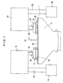
- FIG. 1 is a front elevational view of a polishing apparatus having a dressing apparatus according to the present invention.
- the polishing apparatus comprises a polishing table 5 having a polishing pad (or fixed abrasive) 1 attached to the upper surface thereof, a top ring 10 for holding a semiconductor wafer W as a substrate and pressing the semiconductor wafer W against a polishing surface 1a comprising an upper surface of the polishing pad 1, and a dressing apparatus 20 for dressing an upper surface (polishing surface 1a) of the polishing pad (or fixed abrasive).
- a slurry-like polishing liquid containing abrasive particles is supplied from a polishing liquid supply nozzle 27 onto the polishing surface 1a of the polishing pad 1.
- a guide ring 11 is provided on an outer circumferential portion of the top ring 10 to prevent the semiconductor wafer W from being disengaged from the top ring 10.
- the top ring 10 is supported from a top ring arm 12 by a top ring drive shaft 15.
- the top ring arm 12 is supported by a support shaft 13 which can be angularly positioned, and the top ring 10 can access the polishing table 5 and a pusher (not shown) by rotating the support shaft 13 with a motor 14.
- the pusher serves as a transfer device for transferring the semiconductor wafer between the top ring 10 and the pusher.
- the dressing apparatus 20 comprises a dresser head 21, and a dressing member 22 fixed to the dresser head 21.
- the dresser head 21 is supported from a dresser arm 24 by a dresser drive shaft 23.
- the dresser arm 24 is supported by an angularly positionable support shaft 25, and the dresser head 21 can access the polishing table 5 and a standby position by rotating the support shaft 25 with a motor 26.
- the polishing pad 1a comprises a disk-like member which is composed of polyurethane foam, or nonwoven fabric composed of fibers bound with urethane resin.
- the fixed abrasive is composed of abrasive particles of CeO 2 or SiO 2 or Al 2 O 3 which are fixed by a binder comprising thermosetting resin such as epoxy resin or phenolic resin, or thermoplastic resin such as methylmethacrylate butadiene styrene or acrylonitrile butadiene styrene.
- the abrasive particles have an average particle diameter of 0.5 ⁇ m or less.
- the semiconductor wafer W is held by the lower surface of the top ring 10 and pressed against the polishing pad (or fixed abrasive) 1 on the polishing table 5 by the top ring 10, while the polishing table 5 and the top ring 10 are rotated. Therefore, the semiconductor wafer W is polished by a relative sliding motion between the polishing pad 1 and the semiconductor wafer W. At this time, a polishing liquid is supplied onto the polishing surface 1a of the polishing pad 1 from the polishing liquid supply nozzle 27.
- the polishing liquid comprises abrasive particles such as silica (SiO 2 ) particles, and chemical solution such as alkaline solution in which the abrasive particles are suspended.
- abrasive particles such as silica (SiO 2 ) particles
- chemical solution such as alkaline solution in which the abrasive particles are suspended.
- a dressing liquid such as pure water is supplied onto the polishing surface 1a of the polishing pad 1 on the rotating polishing table 5 from a dressing liquid supply device (not shown), and while the dresser head 21 of the dressing apparatus 20 is rotated, the dressing member 22 is pressed against the polishing surface 1a.
- the polishing surface 1a is scraped slightly in the order of ⁇ m to remove the abrasive particles in the polishing liquid and the ground-off particles, thus regenerating the polishing surface 1a and keeping the polishing surface 1a in a constant condition at all times.
- FIG. 1 The structural details of the dressing apparatus shown in FIG. 1 will be described below with reference to FIGS. 2 through 8 .
- FIG. 2 shows in cross section a dressing apparatus according to a first embodiment of the present invention.
- a dressing apparatus 20 comprises a dresser head 21 connected to a dresser drive shaft 23, and a dressing member 22 fixed to the dresser head 21.
- the dresser head 21 comprises a dresser body 31 coupled to the dresser drive shaft 23, and a disk-shaped dresser plate 32 which holds the dressing member 22.
- the dresser head 21 further comprises a gimbal mechanism 33 interconnecting the dresser body 31 and the dresser plate 32 such that the dresser plate 32 is tiltable with respect to the dresser body 31, and a rotation transmitting mechanism 40 for transmitting the rotation of the dresser drive shaft 23 to the dresser plate 32.
- the dresser body 31 and the dresser drive shaft 23 may be connected to each other through another member without direct coupling.
- the gimbal mechanism 33 is disposed in a downwardly open recess 31a formed centrally in a lower portion of the dresser body 31.
- the gimbal mechanism 33 comprises a spherical slide bearing 34, a centering shaft 35 fixed to the dresser plate 32, and a linear bearing 36 inserted between the spherical bearing 34 and the centering shaft 35.
- the spherical bearing 34 comprises a fixed member 37 fixed to the dresser body 31 and having a hemispherical concave surface, and a substantially spherical movable member 38 slidably fitted in the hemispherical concave surface of the fixed member 37.
- the linear bearing 36 is inserted and fixedly positioned in the substantially spherical movable member 38.
- the centering shaft 35 fixed to the dresser plate 32 is fitted in the linear bearing 36.
- the centering shaft 35 is vertically movable with respect to the linear bearing 36, and the linear bearing 36 and the movable member 38 are rotatable with respect to the fixed member 37. Therefore, the spherical bearing 34 allows the dresser plate 32 to be tilted and the linear bearing 36 allows the dresser plate 32 to be moved vertically without causing the dresser plate 32 to be brought out of coaxial alignment with the dresser body 31.
- the rotation transmitting mechanism 40 has a plurality of torque transmitting pins 41 mounted on the dresser plate 32 at angularly spaced intervals along a certain circumferential pattern and fixed to the dresser plate 32.
- the torque transmitting pins 41 extend vertically through respective through-holes 31b formed in an outer circumferential flange of the dresser body 31.
- FIG. 3 shows one of the torque transmitting pins 41 in detail, the view being a cross-sectional view taken along line III - III of FIG. 2 .
- the torque transmitting pins 41 are identical in structure to each other, and one of the torque transmitting pins 41 will be described below.
- two spaced pins 42 are horizontally disposed in the dresser body 31 one on each side of the torque transmitting pin 41 and extend partly through the through-hole 31b.
- a damper sleeve 43 made of rubber or the like is fitted over the torque transmitting pin 41.
- the torque transmitting pin 41 and the pins 42 engage each other through the damper sleeve 43.
- the dresser body 31 rotates in unison with the dresser drive shaft 23.
- the rotation of the dresser body 31 is transmitted to the dresser plate 32 through the engagement between the torque transmitting pin 41 and the pins 42.
- the dresser plate 32 is tilted so as to follow the inclination (or undulation) of the polishing surface 1a.
- the torque transmitting pins 41 have respective stoppers 41a, mounted on their upper ends, which are larger in size than the inner diameters of the through-holes 31b.
- the stoppers 41a engage the upper surface of the dresser body 31, thus preventing the dresser plate 32 from falling from the dresser body 31.
- the dresser plate 32 is combined with a plurality of load adjusting mechanisms 47 comprising weights 45 fixed to the dresser plate 32 by bolts 46.
- the load adjusting mechanisms 47 are disposed at angularly equally spaced intervals along a certain circumferential pattern on the dresser plate 32. The number of weights 45 of each of the load adjusting mechanisms 47 can be selected as desired.
- covers 48 and 49 are mounted on the dresser body 31 and the dresser plate 32, respectively.
- the dressing member 22 fixed to the dresser head 21 may be of an annular shape as shown FIG. 2 or a disk shape. Diamond particles are electrodeposited on the lower surface of the dressing member 22.
- the dressing member 22 may be made of ceramics such as SiC or may be made of any of various other materials.
- An air cylinder (not shown) housed in the dresser arm 24 (see FIG. 1 ) is actuated to lower the dresser drive shaft 23 together with the dresser head 21.
- the stoppers 41a are held in engagement with the upper surface of the dresser body 31.
- the dresser drive shaft 23 is lowered by a predetermined distance to bring the dressing member 22 into contact with the polishing surface 1a of the polishing table 5.
- the centering shaft 35 slides in the linear bearing 36, and the dressing apparatus 20 becomes in such a state shown in FIG. 2 .
- the dresser drive shaft 23 is rotated about its own axis, and the dressing member 22 is brought in sliding contact with the polishing surface 1a, thereby dressing the polishing surface 1a.
- the dressing load applied to the polishing surface 1a by the dressing member 22 is imposed only by the dresser plate 32 and the parts fixed to the dresser plate 32, and hence such dressing load is relatively small.
- the dressing load is imposed by the dresser plate 32, the dressing member 22, the torque transmitting pins 41, the centering shaft 35, the load adjusting mechanisms 47, and the cover 49, i.e., the weight of the movable assembly of the dresser head 21, and hence such dressing load is a light load.
- the movable assembly of the dresser head 21 is movable with respect to the dresser body 31. Since the dressing load is small, an amount of material removed from the polishing surface 1a when the polishing surface 1a is dressed can be minimized.
- the dressing load can be adjusted to an optimum small load by adjusting the load applied by the load adjusting mechanisms 47.
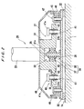
- FIG. 4 shows in cross section a dressing apparatus according to a second embodiment of the present invention.
- a dressing apparatus 20 comprises a dresser head 21 connected to a dresser drive shaft 23, and a dressing member 22 fixed to the dresser head 21.
- the dresser head 21 comprises a dresser body 31 coupled to the dresser drive shaft 23, a disk-shaped dresser plate 32 which holds the dressing member 22, a gimbal mechanism 33 interconnecting the dresser body 31 and the dresser plate 32 such that the dresser plate 32 is tiltable with respect to the dresser body 31, and an annular resilient membrane 50 which couples the dresser plate 32 and the dresser body 31 to each other.
- the dresser plate 32 and the dresser body 31 are coupled to each other by the annular resilient membrane 50 which has an outer circumferential edge portion sandwiched between a cylindrical projection 51 fixed to the dresser plate 32 and a substantially cylindrical stopper ring 52 and an inner circumferential edge portion sandwiched between the lower surface of the peripheral edge portion of the dresser body 31 and an annular holder ring 53.
- the resilient membrane 50 is made of EPDM (ethylene propylene diene monomer), polyurethane rubber, silicone rubber, or the like, and should preferably be resistant to corrosion.
- the dresser body 31, the resilient membrane 50, and the dresser plate 32 jointly define a hermetically sealed space 54 surrounded thereby.
- the hermetically sealed space 54 is connected to a fluid passage 55 which extends through a through-hole (not shown) formed in the dresser drive shaft 23 and is connected to a pressurized fluid source and/or a vacuum source via a rotary joint, a regulator, a directional control valve, etc.
- the pressure in the hermetically sealed space 54 can be adjusted to any desired pressure ranging from a positive pressure to a negative pressure.
- the stopper ring 52 has a stopper 52a extending radially inwardly from the upper end thereof. When the dresser head 21 is lifted, the stopper 52a engages the upper surface of the dresser body 31, thus preventing the dresser plate 32 from falling from the dresser body 31.
- the gimbal mechanism 33, the dressing member 22, the covers 48 and 49, and other components of the dressing apparatus according to the second embodiment are identical to those of the dressing apparatus 20 according to the first embodiment.
- FIG. 4 Operation of the dressing apparatus constructed as shown in FIG. 4 will be described below.
- An air cylinder (not shown) housed in the dresser arm 24 (see FIG. 1 ) is actuated to lower the dresser drive shaft 23 together with the dresser head 21.
- the stopper 52a is held in engagement with the upper surface of the dresser body 31.
- the dresser drive shaft 23 is lowered by a predetermined distance to bring the dressing member 22 into contact with the polishing surface 1a of the polishing table 5.
- the dressing member 22 contacts the polishing surface 1a of the polishing table 5
- only the dresser shaft 23 and the dresser body 31 are lowered, with the result that the stopper 52a is disengaged from the dresser body 31.
- the centering shaft 35 slides in the linear bearing 36, and the dressing apparatus 20 becomes in such a state shown in FIG. 4 .
- the dresser drive shaft 23 is rotated about its own axis, and the dressing member 22 is brought in sliding contact with the polishing surface 1a, thereby dressing the polishing surface 1a.
- the dressing load applied to the polishing surface 1a by the dressing member 22 is imposed only by the dresser plate 32 and the parts fixed to the dresser plate 32, and hence such dressing load is relatively small.
- the dressing load is imposed by the dresser plate 32, the dressing member 22, the projection 51, the stopper ring 52, the centering shaft 35, and the cover 49, i.e., the weight of the movable assembly of the dresser head 21, and hence such dressing load is a light load. Since the dressing load is small, an amount of material removed from the polishing surface 1a when the polishing surface 1a is dressed can be minimized.
- the hermetically sealed space 54 is connected to the vacuum source and the negative pressure in the hermetically sealed space 54 is regulated by the regulator to provide a balance between the weight of the movable assembly of the dresser head 21 and the negative pressure in the hermetically sealed space 54. In this manner, a smaller dressing load is achieved.
- the hermetically sealed space 54 is connected to a pressurized fluid source and supplied with a pressurized fluid such as compressed air from the pressurized fluid source, and the positive pressure in the hermetically sealed space 54 is regulated by the regulator, then the pressing force applied by the pressurized fluid is added to the weight of the movable assembly of the dresser head 21, thus applying a dressing load greater than the weight of the movable assembly of the dresser head 21 to the polishing surface 1a.
- the dressing apparatus 20 should preferably be operated as follows:
- FIGS. 5 and 6 show in cross section a dressing apparatus according to a third embodiment of the present invention.
- FIG. 5 shows the state in which the dressing apparatus is lifted from the polishing table
- FIG. 6 shows the state in which the dressing apparatus performs dressing of the polishing surface.
- a dressing apparatus 20 comprises a dresser head 21 connected to a dresser drive shaft 23, and a dressing member 22 fixed to the dresser head 21.
- the dresser head 21 comprises a dresser body 31 coupled to the dresser drive shaft 23, a disk-shaped dresser plate 32 which holds the dressing member 22, a gimbal mechanism 33 interconnecting the dresser body 31 and the dresser plate 32 such that the dresser plate 32 is tiltable with respect to the dresser body 31, and a rotation transmitting mechanism 40 for transmitting the rotation of the dresser drive shaft 23 to the dresser plate 32.
- the gimbal mechanism 33 is disposed in an upwardly open recess 32a defined centrally in an upper portion of the dresser plate 32.
- the gimbal mechanism 33 comprises a spherical slide bearing 34, a centering shaft 35 fixed to the dresser body 31, and a linear bearing 36 inserted between the spherical bearing 34 and the centering shaft 35.
- the spherical bearing 34 comprises a fixed member 37 fixed to the dresser plate 32 and having a hemispherical concave surface, and a substantially spherical movable member 38 slidably fitted in the hemispherical concave surface of the fixed member 37.
- the linear bearing 36 is inserted and fixedly positioned in the substantially spherical movable member 38.
- the centering shaft 35 fixed to the dresser plate 32 is fitted in the linear bearing 36.
- the centering shaft 35 is vertically movable with respect to the linear bearing 36, and the linear bearing 36 and the movable member 38 are rotatable with respect to the fixed member 37. Therefore, the spherical bearing 34 allows the dresser plate 32 to be tilted and the linear bearing 36 allows the dresser plate 32 to be moved vertically without causing the dresser plate 32 to be brought out of coaxial alignment with the dresser body 31.
- the rotation transmitting mechanism 40 has a plurality of torque transmitting pins 41 mounted on the dresser plate 32 at angularly spaced intervals along a certain circumferential pattern and fixed to the dresser plate 32.
- the torque transmitting pins 41 extend vertically through respective through-holes 31b formed in an outer circumferential flange of the dresser body 31.
- two spaced pins 42 are horizontally disposed in the dresser body 31 one on each side of each of the torque transmitting pin 41 and extend partly through each of the through-hole 31b.
- a damper sleeve 43 made of rubber or the like is fitted over the torque transmitting pin 41.
- the torque transmitting pin 41 and the pins 42 engage each other through the damper sleeve 43.
- the dresser plate 32 is tilted so as to follow the inclination of the polishing surface 1a.
- the torque transmitting pin 41 on the dresser plate 32 and the pins 42 on the dresser body 31 engage each other through point-to-point contact, the torque transmitting pin 41 and the pins 42 are held in reliable engagement while varying points of contact, thus allowing the rotational forces of the dresser drive shaft 23 to be transmitted reliably to the dresser plate 32.
- the torque transmitting pins 41 have respective stoppers 41a, mounted on their upper ends, which are larger in size than the inner diameters of the through-holes 31b.
- the stoppers 41a engage the upper surface of the dresser body 31, thus preventing the dresser plate 32 from being dislodged from the dresser body 31.
- the dressing member 22, the covers 48 and 49, and other components are identical to those of the first embodiment of the present invention.
- An L-shaped arm 60 is fixedly mounted on the dresser plate 32, and has an upper portion projecting upwardly of the dresser body 31.
- the L-shaped arm 60 has a radially inward projection 60a supporting a tubular bellows-shaped resilient membrane 61 on its lower surface and a disk-shaped pressure plate 62 mounted on the lower end of the tubular bellows-shaped resilient membrane 61.
- the resilient membrane 61 and the pressure plate 62 jointly constitutes an air bag 63. Further, the air bag 63 constitutes a hermetically sealed space.
- the resilient membrane 61 is made of EPDM (ethylene propylene diene monomer), polyurethane rubber, silicone rubber, or the like, and should preferably be resistant to corrosion.
- the air bag 63 and the L-shaped arm 60 should preferably be provided in a plurality of sets spaced at angularly equally spaced intervals along a certain circumferential pattern on the dresser plate 32.
- the air bag 63 and the L-shaped arm 60 are provided in three sets at angularly equally spaced intervals of 120°.
- the L-shaped arm 60 may be of an annular shape.
- the pressure plate 62 is not fixed to the upper surface of the dresser body 31, but is held in slidable engagement therewith.
- a fluid passage 55 is connected to the air bag 63 and extends through a through-hole (not shown) formed in the dresser drive shaft 23, and is connected to a pressurized fluid source and/or a vacuum source via a rotary joint, a regulator, a directional control valve, etc.
- the pressure in the air bag 63 can be adjusted to any desired pressure ranging from a positive pressure to a negative pressure.
- a pressurized fluid such as compressed air is supplied through the fluid passage 55 to the air bag 63, the air bag 63 is inflated, thus applying upward forces to the dresser plate 32.
- the pressure of the pressurized fluid can be regulated by the regulator to control the dressing load based on a balance between the pressure of the pressurized fluid and the weight of the movable assembly of the dresser head 21.
- the movable assembly of the dresser head 21, which includes the dresser plate 32, the dressing member 22, the torque transmitting pins 41, the cover 49, the L-shaped member 60, the spherical bearing 34, and the linear bearing 36, has a total weight of about 12 kg.
- the dressing load can be controlled in a range of from about 0 N to about 120 N by a balance between the weight of the movable assembly of the dresser head 21 and the positive pressure in the air bags 63. Because positive pressures can generally be controlled in a wider range and with greater ease than negative pressures, it is preferable to equalize the weight of the movable assembly of the dresser head 21 and a maximum dressing load that is required, and control the dressing load based on the positive pressure in the air bags 63.
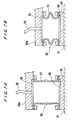
- FIGS. 7A and 7B show the manner in which the air bag 63 shown in FIGS. 5 and 6 operate.
- FIG. 7A shows the state in which the air bag 63 is inflated
- FIG. 7B shows the state in which the air bag 63 is deflated, i.e., no pressure is applied to the air bag 63.
- the pressurized fluid is introduced into the air bag 63 to inflate the air bag 63, thus expanding the resilient membrane 61 to cause the pressure plate 62 to press the dresser body 31.
- an upward force is applied to the dresser plate 32.
- FIG. 7B no pressure is applied to the air bag 63 to deflate the air bag 63, thus contracting the resilient membrane 61. Therefore, the pressure plate 62 does not press the dresser body 31, and no upward force is applied to the dresser plate 32.
- recesses 65 and 66 may be formed respectively in a lower surface of the projection 60a of the L-shaped arm 60 and an upper surface of the pressure plate 62 for keeping the areas of upper and lower surfaces in the air bag 63 constant even when the resilient membrane 61 is somewhat flexed.
- An air cylinder (not shown) housed in the dresser arm 24 (see FIG. 1 ) is actuated to lower the dresser drive shaft 23 together with the dresser head 21 from the position shown in FIG. 5 .
- the stoppers 41a are held in engagement with the upper surface of the dresser body 31.
- the dresser drive shaft 23 is lowered by a predetermined distance to bring the dressing member 22 into contact with the polishing surface 1a of the polishing table 5. After the dressing member 22 contacts the polishing surface 1a of the polishing table 5, only the dresser shaft 23 and the dresser body 31 are lowered, with the result that the stoppers 41a are disengaged from the dresser body 31.
- the centering shaft 35 slides in the linear bearing 36, and the dressing apparatus 20 becomes in such a state shown in FIG. 6 . Because the dresser drive shaft 23 is lowered until any flexing of the resilient membrane 61 is removed, the areas of the upper and lower surfaces in the air bag 63 are kept constant by the recesses 65 and 66, regardless of slight wear of the polishing surface 1a when the polishing surface 1a is dressed.
- the dresser drive shaft 23 is rotated about its own axis, and the dressing member 22 is brought in sliding contact with the polishing surface 1a, thereby dressing the polishing surface 1a.
- the dressing load applied to the polishing surface 1a by the dressing member 22 is imposed only by the dresser plate 32 and the parts fixed to the dresser plate 32, and hence such dressing load is relatively small.
- the dressing load is imposed by the dresser plate 32, the dressing member 22, the torque transmitting pins 41, the spherical bearing 34, the linear bearing 36, the L-shaped member 60, and the cover 49, i.e., the weight of the movable assembly of the dresser head 21, and hence such dressing load is small. Since the dressing load is small, an amount of material removed from the polishing surface 1a when the polishing surface 1a is dressed can be minimized.
- the air bags 63 are connected to the pressurized fluid source and the fluid pressure in the air bags 63 is regulated by the regulator to provide a balance between the weight of the movable assembly of the dresser head 21 and the fluid pressure in the air bags 63 for thereby achieving a desired light dressing load.
- the dressing apparatus 20 should preferably be operated as follows:
- FIG. 8 shows in cross section a modification of the dressing apparatus according to the third embodiment of the present invention shown in FIGS. 5 and 6 .
- the air bags 63 are disposed between the upper surface of the dresser body 31 and the L-shaped members 60 fixed to the dresser plate 32.
- the air bags 63 constituting a hermetically sealed space are disposed between the lower surface of the dresser body 31 and the upper surface of the dresser plate 32.
- the air bags 63 are disposed to connect the lower surface of the dresser body 31 and the upper surface of the dresser plate 32 to each other with the resilient members 61. Operation of the dressing apparatus according to the embodiment shown in FIG.
- the dressing load is imposed by the dresser plate 32, the dressing member 22, the spherical bearing 34, the linear bearing 36, the torque transmitting pins 41, and the cover 49, i.e., the weight of the movable assembly of the dresser head 21, and hence such dressing load is a light load.
- the air bags 63 are connected to the vacuum source, and the negative pressure in the air bags 63 is regulated by the regulator to provide a balance between the weight of the movable assembly of the dresser head 21 and the negative pressure in the air bags 63 for thereby achieving a desired small dressing load.
- the air bags 63 are connected to the pressurized fluid source and supplied with a pressurized fluid such as compressed air from the pressurized fluid source, and the positive pressure in the air bags 63 is regulated by the regulator, thus adding the pressing force imposed by the pressurized fluid to the weight of the movable assembly of the dresser head 21. Therefore, a large dressing load can be applied to the polishing surface 1a.
- Recesses 65 and 66 formed in upper and lower surfaces in the air bags 63 provide constant pressure-bearing areas in the air bags 63, thus achieving accurate load control.
- the polishing pad or fixed abrasive When the polishing pad or fixed abrasive is replaced with a new one, it is dressed to initialize the polishing surface 1a.
- the amount of material removed from the polishing pad or fixed abrasive by dressing of the polishing surface 1a for initialization is much greater than the amount of material removed from the polishing pad or fixed abrasive by dressing of the polishing surface 1a during polishing of the workpiece or between polishing of the workpieces. Accordingly, if the dressing load is too small in the initial dressing process, then it is time-consuming to initialize the polishing surface 1a, and the serviceability ratio of the polishing apparatus is lowered.
- the dressing load can be changed only by the control of the regulator. Specifically, when the polishing surface 1a is initialized, it is dressed under a relatively large dressing load of about 100 N to perform the initializing process at an accelerated rate. After the polishing surface 1a is thus quickly initialized, the polishing surface 1a is readily available to polish desired workpieces. If the polishing surface 1a is dressed at the same time that it polishes the workpiece, then the polishing surface 1a is dressed under a small dressing load ranging from 1 N to 5 N. If the polishing surface 1a is dressed between polishing cycles, i.e.
- the polishing surface 1a is dressed under a small dressing load ranging from 5 N to 20 N. Further, if necessary, the polishing surface 1a is dressed under a dressing load ranging from 0 N to 100 N or a higher dressing load.
- the dressing load to be applied to dress the polishing surface of the polishing table can be reduced, the amount of material removed from the polishing surface when it is dressed can be minimized, and the service life of the polishing pad or fixed abrasive can be increased. Consequently, the running cost of the polishing apparatus can be lowered.
- the present invention relates to a dressing apparatus and a polishing apparatus for polishing a workpiece such as a semiconductor wafer to a planar finish, and is preferably utilized in manufacturing semiconductor devices.
Landscapes
- Engineering & Computer Science (AREA)
- Mechanical Engineering (AREA)
- Physics & Mathematics (AREA)
- Condensed Matter Physics & Semiconductors (AREA)
- General Physics & Mathematics (AREA)
- Manufacturing & Machinery (AREA)
- Computer Hardware Design (AREA)
- Microelectronics & Electronic Packaging (AREA)
- Power Engineering (AREA)
- Finish Polishing, Edge Sharpening, And Grinding By Specific Grinding Devices (AREA)
- Mechanical Treatment Of Semiconductor (AREA)
- Grinding-Machine Dressing And Accessory Apparatuses (AREA)
Applications Claiming Priority (3)
| Application Number | Priority Date | Filing Date | Title |
|---|---|---|---|
| JP2001011730A JP4072810B2 (ja) | 2001-01-19 | 2001-01-19 | ドレッシング装置および該ドレッシング装置を備えたポリッシング装置 |
| JP2001011730 | 2001-01-19 | ||
| PCT/JP2002/000274 WO2002057051A1 (en) | 2001-01-19 | 2002-01-17 | Dressing apparatus and polishing apparatus |
Publications (2)
| Publication Number | Publication Date |
|---|---|
| EP1261454A1 EP1261454A1 (en) | 2002-12-04 |
| EP1261454B1 true EP1261454B1 (en) | 2012-08-01 |
Family
ID=18878832
Family Applications (1)
| Application Number | Title | Priority Date | Filing Date |
|---|---|---|---|
| EP02715775A Expired - Lifetime EP1261454B1 (en) | 2001-01-19 | 2002-01-17 | Dressing apparatus and polishing apparatus |
Country Status (6)
| Country | Link |
|---|---|
| US (1) | US6899604B2 (enExample) |
| EP (1) | EP1261454B1 (enExample) |
| JP (1) | JP4072810B2 (enExample) |
| KR (1) | KR100798438B1 (enExample) |
| TW (1) | TWI236949B (enExample) |
| WO (1) | WO2002057051A1 (enExample) |
Families Citing this family (17)
| Publication number | Priority date | Publication date | Assignee | Title |
|---|---|---|---|---|
| JP3922887B2 (ja) * | 2001-03-16 | 2007-05-30 | 株式会社荏原製作所 | ドレッサ及びポリッシング装置 |
| US7288165B2 (en) * | 2003-10-24 | 2007-10-30 | Applied Materials, Inc. | Pad conditioning head for CMP process |
| WO2007082556A1 (en) * | 2006-01-23 | 2007-07-26 | Freescale Semiconductor, Inc. | Method and apparatus for conditioning a cmp pad |
| CN100441377C (zh) * | 2006-12-05 | 2008-12-10 | 中国科学院上海光学精密机械研究所 | 用于环行抛光机的校正板 |
| US8042240B2 (en) | 2007-01-26 | 2011-10-25 | Honda Motor Co., Ltd. | Machine tool |
| JP4382099B2 (ja) * | 2007-01-26 | 2009-12-09 | 本田技研工業株式会社 | 工作機械 |
| JP5236515B2 (ja) * | 2009-01-28 | 2013-07-17 | 株式会社荏原製作所 | ドレッシング装置、化学的機械的研磨装置及び方法 |
| CN105122428B (zh) * | 2013-04-19 | 2017-11-28 | 应用材料公司 | 多盘化学机械抛光衬垫调节器与方法 |
| JP6592355B2 (ja) * | 2015-01-30 | 2019-10-16 | 株式会社荏原製作所 | 連結機構および基板研磨装置 |
| US10814457B2 (en) * | 2018-03-19 | 2020-10-27 | Globalfoundries Inc. | Gimbal for CMP tool conditioning disk having flexible metal diaphragm |
| KR102128780B1 (ko) * | 2018-12-03 | 2020-07-01 | 한국생산기술연구원 | Cmp설비용 컨디셔닝장치의 디스크결합체 |
| KR102705647B1 (ko) | 2019-05-02 | 2024-09-11 | 삼성전자주식회사 | 컨디셔너, 이를 포함하는 화학 기계적 연마 장치 및 이 장치를 이용한 반도체 장치의 제조 방법 |
| CN110125745A (zh) * | 2019-05-27 | 2019-08-16 | 广东技术师范大学 | 一种工业抛光打磨机器人 |
| CN113183031A (zh) * | 2021-05-20 | 2021-07-30 | 杭州众硅电子科技有限公司 | 一种修整头旋转部件、抛光垫修整头和修整器 |
| CN114193326A (zh) * | 2021-12-22 | 2022-03-18 | 莱玛特·沃尔特斯(沈阳)精密机械有限公司 | 一种抛光机的抛光盘修整装置 |
| CN115771086A (zh) * | 2022-11-15 | 2023-03-10 | 重庆大学 | 一种万向浮动打磨机构 |
| CN116021427B (zh) * | 2023-02-01 | 2025-06-24 | 江西联洲研磨科技有限公司 | 一种树脂砂轮加工用表面修整装置 |
Family Cites Families (9)
| Publication number | Priority date | Publication date | Assignee | Title |
|---|---|---|---|---|
| JPS5981056A (ja) | 1982-10-29 | 1984-05-10 | Tohoku Metal Ind Ltd | 定盤修正装置 |
| US5885137A (en) * | 1997-06-27 | 1999-03-23 | Siemens Aktiengesellschaft | Chemical mechanical polishing pad conditioner |
| US6200199B1 (en) | 1998-03-31 | 2001-03-13 | Applied Materials, Inc. | Chemical mechanical polishing conditioner |
| US6263605B1 (en) * | 1998-12-21 | 2001-07-24 | Motorola, Inc. | Pad conditioner coupling and end effector for a chemical mechanical planarization system and method therefor |
| JP3045236B1 (ja) | 1999-01-18 | 2000-05-29 | 株式会社東京精密 | 研磨布コンディショナを備えたウェハ研磨装置 |
| JP3945940B2 (ja) | 1999-06-02 | 2007-07-18 | 東京エレクトロン株式会社 | 試料研磨方法及び試料研磨装置 |
| US6217429B1 (en) * | 1999-07-09 | 2001-04-17 | Applied Materials, Inc. | Polishing pad conditioner |
| JP2001246550A (ja) | 2000-03-02 | 2001-09-11 | Ebara Corp | 研磨装置 |
| US6572446B1 (en) * | 2000-09-18 | 2003-06-03 | Applied Materials Inc. | Chemical mechanical polishing pad conditioning element with discrete points and compliant membrane |
-
2001
- 2001-01-19 JP JP2001011730A patent/JP4072810B2/ja not_active Expired - Lifetime
-
2002
- 2002-01-17 EP EP02715775A patent/EP1261454B1/en not_active Expired - Lifetime
- 2002-01-17 US US10/204,600 patent/US6899604B2/en not_active Expired - Lifetime
- 2002-01-17 WO PCT/JP2002/000274 patent/WO2002057051A1/en not_active Ceased
- 2002-01-17 KR KR1020027012337A patent/KR100798438B1/ko not_active Expired - Lifetime
- 2002-01-18 TW TW091100738A patent/TWI236949B/zh not_active IP Right Cessation
Also Published As
| Publication number | Publication date |
|---|---|
| JP4072810B2 (ja) | 2008-04-09 |
| JP2002210650A (ja) | 2002-07-30 |
| EP1261454A1 (en) | 2002-12-04 |
| TWI236949B (en) | 2005-08-01 |
| US6899604B2 (en) | 2005-05-31 |
| US20030148707A1 (en) | 2003-08-07 |
| WO2002057051A1 (en) | 2002-07-25 |
| KR20020092993A (ko) | 2002-12-12 |
| KR100798438B1 (ko) | 2008-01-28 |
Similar Documents
| Publication | Publication Date | Title |
|---|---|---|
| EP1261454B1 (en) | Dressing apparatus and polishing apparatus | |
| EP1240977B1 (en) | Polishing apparatus | |
| US7357699B2 (en) | Substrate holding apparatus and polishing apparatus | |
| EP1197292B1 (en) | Substrate holding apparatus | |
| US7108592B2 (en) | Substrate holding apparatus and polishing apparatus | |
| US6143127A (en) | Carrier head with a retaining ring for a chemical mechanical polishing system | |
| US20070212988A1 (en) | Polishing apparatus | |
| JP2003173995A (ja) | 基板保持装置及びポリッシング装置 | |
| CN100468643C (zh) | 衬底保持装置以及抛光装置 | |
| EP1495837B1 (en) | Polishing method |
Legal Events
| Date | Code | Title | Description |
|---|---|---|---|
| PUAI | Public reference made under article 153(3) epc to a published international application that has entered the european phase |
Free format text: ORIGINAL CODE: 0009012 |
|
| 17P | Request for examination filed |
Effective date: 20020826 |
|
| AK | Designated contracting states |
Kind code of ref document: A1 Designated state(s): AT BE CH CY DE DK ES FI FR GB GR IE IT LI LU MC NL PT SE TR |
|
| AX | Request for extension of the european patent |
Free format text: AL;LT;LV;MK;RO;SI |
|
| 17Q | First examination report despatched |
Effective date: 20100917 |
|
| GRAP | Despatch of communication of intention to grant a patent |
Free format text: ORIGINAL CODE: EPIDOSNIGR1 |
|
| GRAS | Grant fee paid |
Free format text: ORIGINAL CODE: EPIDOSNIGR3 |
|
| GRAA | (expected) grant |
Free format text: ORIGINAL CODE: 0009210 |
|
| AK | Designated contracting states |
Kind code of ref document: B1 Designated state(s): DE FR |
|
| REG | Reference to a national code |
Ref country code: DE Ref legal event code: R096 Ref document number: 60243420 Country of ref document: DE Effective date: 20120927 |
|
| PLBE | No opposition filed within time limit |
Free format text: ORIGINAL CODE: 0009261 |
|
| STAA | Information on the status of an ep patent application or granted ep patent |
Free format text: STATUS: NO OPPOSITION FILED WITHIN TIME LIMIT |
|
| 26N | No opposition filed |
Effective date: 20130503 |
|
| REG | Reference to a national code |
Ref country code: DE Ref legal event code: R097 Ref document number: 60243420 Country of ref document: DE Effective date: 20130503 |
|
| REG | Reference to a national code |
Ref country code: FR Ref legal event code: ST Effective date: 20130930 |
|
| PG25 | Lapsed in a contracting state [announced via postgrant information from national office to epo] |
Ref country code: FR Free format text: LAPSE BECAUSE OF NON-PAYMENT OF DUE FEES Effective date: 20130131 |
|
| PGFP | Annual fee paid to national office [announced via postgrant information from national office to epo] |
Ref country code: DE Payment date: 20210105 Year of fee payment: 20 |
|
| REG | Reference to a national code |
Ref country code: DE Ref legal event code: R071 Ref document number: 60243420 Country of ref document: DE |