EP1258685A1 - Haushaltsgerät, insbesondere Backofen - Google Patents
Haushaltsgerät, insbesondere Backofen Download PDFInfo
- Publication number
- EP1258685A1 EP1258685A1 EP02006952A EP02006952A EP1258685A1 EP 1258685 A1 EP1258685 A1 EP 1258685A1 EP 02006952 A EP02006952 A EP 02006952A EP 02006952 A EP02006952 A EP 02006952A EP 1258685 A1 EP1258685 A1 EP 1258685A1
- Authority
- EP
- European Patent Office
- Prior art keywords
- spring
- carriage
- household appliance
- appliance according
- door
- Prior art date
- Legal status (The legal status is an assumption and is not a legal conclusion. Google has not performed a legal analysis and makes no representation as to the accuracy of the status listed.)
- Granted
Links
- 238000010411 cooking Methods 0.000 title 1
- 230000007246 mechanism Effects 0.000 claims description 9
- 230000006835 compression Effects 0.000 description 10
- 238000007906 compression Methods 0.000 description 10
- 239000002184 metal Substances 0.000 description 9
- 238000005553 drilling Methods 0.000 description 2
- 230000001154 acute effect Effects 0.000 description 1
- 238000004140 cleaning Methods 0.000 description 1
- 230000000295 complement effect Effects 0.000 description 1
- 238000010276 construction Methods 0.000 description 1
- 230000003247 decreasing effect Effects 0.000 description 1
- 230000001419 dependent effect Effects 0.000 description 1
- 238000011161 development Methods 0.000 description 1
- 230000018109 developmental process Effects 0.000 description 1
- 230000000694 effects Effects 0.000 description 1
- 230000009467 reduction Effects 0.000 description 1
- 238000007789 sealing Methods 0.000 description 1
- 230000007704 transition Effects 0.000 description 1
Images


Classifications
-
- F—MECHANICAL ENGINEERING; LIGHTING; HEATING; WEAPONS; BLASTING
- F24—HEATING; RANGES; VENTILATING
- F24C—DOMESTIC STOVES OR RANGES ; DETAILS OF DOMESTIC STOVES OR RANGES, OF GENERAL APPLICATION
- F24C15/00—Details
- F24C15/16—Shelves, racks or trays inside ovens; Supports therefor
- F24C15/162—Co-operating with a door, e.g. operated by the door
Definitions
- the invention relates to a household appliance according to the preamble of the claim 1.
- DE 40 23 949 A1 is a generic household appliance, in particular a Oven, known.
- the oven has an oven muffle, the loading opening attached to sliding trains or to a baking cart by an angularly rigid Oven door that can be moved like a drawer is lockable.
- the push cables are in Slideways guided below the oven muffle.
- the oven has one in the sliding path of at least one push train arranged spring locking device pressing the oven door against a muffle flange.
- the spring catch device has a link guide along the sliding path in opposite directions inclined, spring-loaded guide sections with support rollers attached to the push cables interact.
- the object of the invention is a generic household appliance with increased To provide comfort with little design effort.
- the object is achieved by the features of claim 1, while advantageous refinements and developments of the invention, the dependent claims can be removed.
- the invention relates to a household appliance, in particular an oven a carriage and a door and a spring device.
- the carriage be driven by a force of the spring device is extendable, and with the spring device in the retracted state of the car a smaller force in the direction of extension acts on the car than at least one partially extended condition of the car.
- the force can be limited to the retracted condition of the car, or with the movement of the car in its direction of entry decreasing, whereby the car can be retracted particularly comfortably. Furthermore, by at least reduced force in the retracted state in the opening direction, in particular with a small closing force caused by the weight of the car, a locking mechanism and / or a closing spring can be generated, a secure closing of the door is achieved become.
- the force acting in the extension direction can be sensible with different ones to the expert appearing devices are gradually or continuously reduced, for example via a device that a 'spring support with the retraction of the car a spring that generates the force in the extension direction moves or the spring relaxes or with a spring with a corresponding spring characteristic, etc.
- a lever gearbox one can be special structurally simple and inexpensive mechanism can be achieved.
- the lever gear has articulated levers which are essentially a square, advantageous form a rhombus, with a first diagonal of the square parallel to the direction of extension runs and in a second diagonal perpendicular to the direction of extension of the square is inserted a tension spring tensioning the lever. It can be constructive simply with a few components, a relative movement at an articulation point between the lever gear and the carriage and at a pivot point between the lever gear and a housing part of the household appliance can be avoided. in principle
- lever gears that appear useful to the person skilled in the art conceivable, for example, the lever gear from a single pivotable lever be educated, etc.
- the door in its closed position via the spring device is loaded with a closing force, which makes it particularly safe with a high Sealing effect can be closed.
- the spring device has at least one bistable spring unit, a spring unit, especially with a spring, both a force in the closing direction of the door a force in the direction of extension of the carriage can also be achieved. Additional components and Space can be saved.
- the spring device comprises at least a first one acting in the closing direction of the door and a second spring unit acting in the direction of extension of the carriage the differently acting forces can be achieved in a particularly constructive manner and possibly can also be dimensioned differently.
- Closing force of the first spring unit advantageously via an actuating unit for opening the door can be made reducible, so that the car after a reduction in Closing force, automatically driven by the second spring unit.
- a bistable spring unit with a corresponding one can also be used Actuating unit are executed. It is also conceivable to have a bistable spring unit to combine a second spring unit, whereby in one position or over a Distance of the car, the spring units complement each other on the car and / or can act on the door.
- the door is advantageously attached to the carriage and slidably mounted with it.
- the baking trays can be hung directly in the door, one side, the baking trays supporting frame can be saved and there can be advantageous accessibility be achieved.
- the closing force can advantageously be transmitted to the door via the carriage become.
- the door can also be designed to be pivotable.
- the car can be via the door or an additional unit, for example a spring unit and / or a latching unit, etc., kept in its retracted state become.
- the spring device only acts from the retracted state of the car in a first part, advantageously up to half of the total distance with the force in the direction of extension onto the trolley, there can simply be a harmonious movement of the trolley achieved and in particular can automatically in the extension direction at the end of the route a reduced speed of the carriage can be reached before an end position.
- the harmonious movement of the car with a braking unit can be further improved be the car in the direction of extension before its end position over a Braking distance. It can be a particularly smooth transition from the car to his End position can be reached.
- the braking unit can be an undesirable Closing or retracting the car can be avoided.
- the car has at least one Position in the extension direction is decoupled from the spring device, which makes it simple, can be removed completely without great effort, for example Cleaning the car etc.
- the solution according to the invention can be used in various solutions which appear suitable to the person skilled in the art Household appliances are used, such as in dishwashers etc., but especially in the case of ovens, the oven door of which is advantageous by a corresponding Spring device closed particularly securely and together with one The baking cart can be opened comfortably.
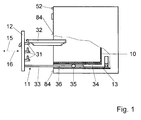
- Fig. 1 shows a schematically illustrated oven in a side view with a Partial section.
- the oven has an oven muffle 10 that faces the front of the oven open and is limited by a muffle flange 84.
- the oven also has a baking cart 11 to which an oven door 12 is attached and connected to the baking cart 11 is slidable. Hook-shaped holding elements 31 are on the oven door 12 attached to which food support 32 can be hung.
- the baking cart 11 has two horizontally extending push cables 33, 85 (FIGS. 1 and 3) which are rigid with the oven door 12 are connected.
- Each push train 33, 85 dips into one below the oven muffle 10 arranged, housing-fixed sliding track 34 and is therein by means of a roller guide horizontally movable.
- each push train 33, 85 has a roller 35, while a support roller 36 is arranged in a stationary manner on each sliding track 34.
- the oven door 12 is in its closed position via a first spring unit 18 of a spring device 13 loaded with a closing force (Fig. 3).
- the spring unit 18 has rear, lower area of the oven a horizontal, transverse to the direction of movement of the baking cart 11 extending guide channel 37, in which a linkage 38 is displaceable is performed (Fig. 1, 2 and 3).
- a roller 45, 46 is rotatably mounted, which is in the closed position the oven door 12 or in the retracted state of the oven 11 with one on the push train 33, 85 integrally formed cam track 47, 48 cooperates and the baking cart 11 thereby loaded in its drive-in direction 16 or onto the oven door 12 acting closing force generated.
- the linkage 38 is between the slides 43, 44 in a recess 49 of the guide channel 37 via pivotable levers 50, 51 with an electromagnetic actuator 21 connected to an actuating unit 20 (Fig. 2, 3 and 5).
- the actuator 21 is in the assembled state via a holding plate 79 on a not shown Oven casing wall attached.
- the baking cart 11 is in the retracted state via a second spring unit 19
- Spring device 13 loaded in its extension direction 15 with a force.
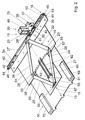
- the spring unit 19 is arranged in the rear, lower area of the oven and has a lever mechanism 22 with hinged levers 23, 24, 25, 26, which essentially form a rhombus, a first diagonal 27 of the rhombus parallel to the Extension direction 15 extends and in a second, perpendicular to the extension direction 15 Diagonals 28 of the rhombus a tension spring bracing the levers 23, 24, 25, 26 29 is attached.
- the rear levers 23, 26 are on the side facing away from the baking cart 11 Floor plate 53 articulated, which also forms a rear wall 54 on which the guide channel 37 of the spring unit 18 is attached.
- On the baking cart 11 facing The rear levers 23, 26 are each articulated via a T-shaped sheet metal part 55, 56 connected to the front levers 24, 25.
- In the T-shaped sheet metal parts 55, 56 is the Tension spring 29 hooked into bores 57, 58.
- the front levers 24, 25 are on hers the side facing the baking cart 11 is articulated on a carriage 59 which is about two guide bolts formed by screws 60, 61 in two guide grooves 62, 63 along of the first diagonals 27 is guided.
- the carriage 59 is formed by a sheet metal part and is guided on a T-shaped plastic base plate 64, which is on a sheet metal base 65 is attached.
- the slide could also be made of plastic instead of sheet metal and run directly on a sheet metal base plate.
- Carriage 59 has an angled area 66, which has a bearing surface 67 for the baking cart 11 forms.
- an operator actuates an actuation button 52 of the actuation unit 20 (FIG. 1).
- the Actuator 21 is activated and a plunger 86 of actuator 21 is retracted electromagnetically (Fig. 6).
- the levers 50, 51 are pivoted and the spring supports 39, 40 are shifted in the guide channel 37 in the direction of the actuator 21, whereby the Helical compression springs 41, 42 are relaxed, and by the first spring unit 18th generated closing force is reduced so that the baking cart 11, driven by the Spring unit 19 can extend.
- the actuator 21 is energy-saving with a short pulse controlled and goes after the baking car 11 with its curved tracks 47, 48th or after a vertex of an inward curve of the cam track 47, 48 has passed the rollers 45, 46 back to its starting position.
- the actuating unit 20 relaxed the helical compression springs 41, 42 Holds position until the baking cart 11 after entering the apex the curved tracks 47, 48 has passed the rollers 45, 46.
- the baking cart 11 can also be extended without actuating the operating button 52 become.
- the slides 43, 44 are on the cam tracks 47, 48, against the Spring force of the helical compression springs 41, 42 deflected.
- the spring unit 19 acts, starting from the retracted state of the baking cart 11 only in a first part of the total distance in the extension direction 15 to the Baking carriage 11, namely on a cross member connected to the sliding trains 33, 85 68 of the baking cart 11 (Fig. 3). After the baking car 11 about half of its has overcome the entire distance in the extending direction 15, the carriage 59 comes Spring unit 19 with the screws 60, 61 at the end of the guide grooves 62, 63 to the system (Fig. 2), and the baking cart 11 is in the extension direction 15 of the spring unit 19 and the entire spring device 13 decouples and moves through its kinetic energy continue in the direction of extension 15.
- the baking cart 11 runs with its cross member 68 on spring-loaded Brake shoes 69, 70 of a brake unit 30 and is defined via a Distance gently braked (Fig. 3).
- the brake shoes 69, 70 are made of plastic shells formed at a front end with a molded hook 71 in one Projection 72 of a lower plastic shell 73 fastened to the sheet metal base 65 is suspended are (Fig. 4).
- the brake shoes 69, 70 are at a rear end via a latching connection 74, 75 snapped onto the lower plastic shells 73 and are over the Snap connection 74, 75 pivotally mounted.
- a helical compression spring 76 Between the brake shoes 69, 70 and lower plastic shell 73 is a helical compression spring 76, via which the Brake shoes 69, 70 are spring-loaded upwards in the direction of the baking carriage 11.
- the baking cart 11 can be inserted comfortably, and the oven muffle 10 can safely with the oven door 12 via the spring unit 18 with a small closing force getting closed.
- the baking cart 11 comes at the end of its path in the direction of entry 16 with its curved tracks 47, 48 with the rollers 45, 46 of the spring unit 18 in System, and the carriage 43, 44 of the spring unit 18 are in the guide channel 37th inserted against the spring force of the helical compression springs 41, 42 until viewed from the rollers 45, 46, an incline 80, 81 of the curved tracks 47, 48 is overcome is, the rollers 45, 46 on a slope 82, 83 of the cam tracks 47, 48 to Lie and the helical compression springs 41, 42 on the carriage 43, 44, the rollers 45, 46 and on the slope 82, 83 of the cam tracks 47, 48 generate a closing force.
- the spring device 13 or the spring units 18, 19 and the brake unit 30 are as executed an assembly that can be assembled and disassembled as a unit in the oven can.
- FIGS. 7 and 8 schematically show an alternative spring device 14 with a bistable Spring unit 17 shown.
- Components that remain essentially the same are fundamental numbered with the same reference numerals.
- FIGS. 1 to 6 are referred. The following description is essentially limited to the differences from the exemplary embodiment in FIGS. 1 to 6.
- the spring unit 17 has a lever mechanism 22 with an articulated connection Levers 23, 24, 25, 26, which essentially form a rhombus, with a first diagonal 27 of the rhombus runs parallel to the extension direction 15 and in a second, The diagonals 28 of the rhombus running perpendicular to the extension direction 15 have the levers 23, 24, 25, 26 tensioning tension spring 29 is attached.
- the spring unit 17 In contrast to the spring unit 19, the spring unit 17 generates a force in the extension direction 15 on a baking cart 11 also a closing force.
- the spring unit 17 is with a front bearing point 77 fixed in the extended state of the baking cart 11 connected to the baking cart 11, the in the retracted state of the baking cart 11 Bearing point 77 is moved behind a bearing point 78, via which the lever mechanism 22nd is attached to a housing part of the oven, so that the tension spring 29 via the lever mechanism 22 acts in the retraction direction 16 on the baking cart 11 and a closing force generated.
Landscapes
- Engineering & Computer Science (AREA)
- Chemical & Material Sciences (AREA)
- Combustion & Propulsion (AREA)
- Mechanical Engineering (AREA)
- General Engineering & Computer Science (AREA)
- Drawers Of Furniture (AREA)
- Baking, Grill, Roasting (AREA)
Abstract
Description
- Fig. 1
- einen schematisch dargestellten Backofen in einer Seitenansicht mit einem Teilschnitt,
- Fig. 2
- eine Federvorrichtung des Backofens aus Fig. 1 schräg von oben in einer einem ausgefahrenen Backwagen zugeordneten Stellung,
- Fig. 3
- die Federvorrichtung aus Fig. 2 in einer Draufsicht in einer dem eingefahrenen Backwagen zugeordneten Stellung,
- Fig. 4
- einen Schnitt entlang der Linie IV-IV in Fig. 3,
- Fig. 5
- einen Ausschnitt V aus Fig. 2 von vorn mit einem Aktuator in einer Verriegelungsstellung,
- Fig. 6
- den Ausschnitt V mit dem Aktuator in einer Entriegelungsstellung,
- Fig. 7
- eine schematische Darstellung einer zu Fig. 2 alternativen Federvorrichtung kurz vor einer einem eingefahrenen Backwagen zugeordneten Stellung,
- Fig. 8
- die Federvorrichtung aus Fig. 7 in einer dem eingefahrenen Backwagen zugeordneten Stellung.
- 10
- Backofenmuffel
- 11
- Backwagen
- 12
- Backofentür
- 13
- Federvorrichtung
- 14
- Federvorrichtung
- 15
- Ausfahrrichtung
- 16
- Einfahrrichtung/Schließrichtung
- 17
- Federeinheit
- 18
- Federeinheit
- 19
- Federeinheit
- 20
- Betätigungseinheit
- 21
- Aktuator
- 22
- Hebelgetriebe
- 23
- Hebel
- 24
- Hebel
- 25
- Hebel
- 26
- Hebel
- 27
- Diagonale
- 28
- Diagonale
- 29
- Zugfeder
- 30
- Bremseinheit
- 31
- Halteelement
- 32
- Gargutträger
- 33
- Schiebezug
- 34
- Verschiebebahn
- 35
- Laufrolle
- 36
- Stützrolle
- 37
- Führungskanal
- 38
- Gestänge
- 39
- Federauflage
- 40
- Federauflage
- 41
- Schraubendruckfeder
- 42
- Schraubendruckfeder
- 43
- Schlitten
- 44
- Schlitten
- 45
- Rolle
- 46
- Rolle
- 47
- Kurvenbahn
- 48
- Kurvenbahn
- 49
- Aussparung
- 50
- Hebel
- 51
- Hebel
- 52
- Betätigungsknopf
- 53
- Bodenblech
- 54
- Rückwand
- 55
- Blechteil
- 56
- Blechteil
- 57
- Bohrung
- 58
- Bohrung
- 59
- Schlitten
- 60
- Schraube
- 61
- Schraube
- 62
- Führungsnut
- 63
- Führungsnut
- 64
- Kunststoff-Bodenplatte
- 65
- Blechboden
- 66
- Bereich
- 67
- Anlagefläche
- 68
- Querträger
- 69
- Bremsbacke
- 70
- Bremsbacke
- 71
- Haken
- 72
- Vorsprung
- 73
- Kunststoffschale
- 74
- Rastverbindung
- 75
- Rastverbindung
- 76
- Schraubendruckfeder
- 77
- Lagerstelle
- 78
- Lagerstelle
- 79
- Halteblech
- 80
- Steigung
- 81
- Steigung
- 82
- Gefälle
- 83
- Gefälle
- 84
- Muffelflansch
- 85
- Schiebezug
- 86
- Stößel
Claims (12)
- Haushaltsgerät, insbesondere Backofen, mit einem Wagen (11) und einer Tür (12) sowie einer Federvorrichtung (13, 14), dadurch gekennzeichnet, daß der Wagen (11) angetrieben durch eine Kraft der Federvorrichtung (13, 14) ausfahrbar ist, und daß die Federvorrichtung (13, 14) im eingefahrenen Zustand des Wagens (11) mit einer kleineren Kraft in Ausfahrrichtung (15) auf den Wagen (11) wirkt als bei einem zumindest teilweise ausgefahrenen Zustand des Wagens (11).
- Haushaltsgerät nach Anspruch 1, dadurch gekennzeichnet, daß die in Ausfahrrichtung (15) wirkende Kraft im eingefahrenen Zustand des Wagens (11) durch ein Hebelgetriebe (22) reduziert ist.
- Haushaltsgerät nach Anspruch 2, dadurch gekennzeichnet, daß das Hebelgetriebe (22) gelenkig miteinander verbundene Hebel (23, 24, 25, 26) aufweist, die im wesentlichen ein Viereck bilden, wobei eine erste Diagonale (27) des Vierecks parallel zur Ausfahrrichtung (15) verläuft und in einer zweiten, senkrecht zur Ausfahrrichtung (15) verlaufenden Diagonalen (28) des Vierecks eine die Hebel (23, 24, 25, 26) verspannende Zugfeder (29) eingebracht ist.
- Haushaltsgerät nach einem der vorhergehenden Ansprüche, dadurch gekennzeichnet, daß die Tür (12) in ihrer Schließstellung über die Federvorrichtung (13, 14) mit einer Schließkraft belastet ist.
- Haushaltsgerät nach Anspruch 4, dadurch gekennzeichnet, daß die Federvorrichtung (14) zumindest eine bistabile Federeinheit (17) aufweist.
- Haushaltsgerät nach Anspruch 4 oder 5, dadurch gekennzeichnet, daß die Federvorrichtung (13) zumindest eine erste, in Schließrichtung (16) der Tür (12) wirkende Federeinheit (18) und eine zweite, in Ausfahrrichtung (15) des Wagens (11) wirkende Federeinheit (19) aufweist.
- Haushaltsgerät nach Anspruch 6, dadurch gekennzeichnet, daß die Schließkraft der ersten Federeinheit (18) über eine Betätigungseinheit (20) zum Öffnen der Tür (12) zumindest reduzierbar ist.
- Bockofen nach Anspruch 7, dadurch gekennzeichnet, daß die Betätigungseinheit (20) einen Aktuator (21) aufweist.
- Haushaltsgerät nach einem der vorhergehenden Ansprüche, dadurch gekennzeichnet, daß die Tür (12) am Wagen (11) befestigt und mit diesem verschiebbar gelagert ist.
- Haushaltsgerät nach einem der vorhergehenden Ansprüche, dadurch gekennzeichnet, daß die Federvorrichtung (13), ausgehend vom eingefahrenen Zustand des Wagens (11) lediglich in einem ersten Teil der gesamten Wegstrecke mit der Kraft in Ausfahrrichtung (15) auf den Wagen (11) wirkt.
- Haushaltsgerät nach einem der vorhergehenden Ansprüche, dadurch gekennzeichnet, daß der Wagen (11) in Ausfahrrichtung (15) vor seiner Endstellung mit einer Bremseinheit (30) über eine Wegstrecke gebremst ist.
- Haushaltsgerät nach einem der vorhergehenden Ansprüche, dadurch gekennzeichnet, daß der Wagen (11) ab zumindest einer Stellung in Ausfahrrichtung (15) von der Federvorrichtung (13, 14) entkoppelt ist.
Applications Claiming Priority (2)
| Application Number | Priority Date | Filing Date | Title |
|---|---|---|---|
| DE10124458 | 2001-05-18 | ||
| DE2001124458 DE10124458A1 (de) | 2001-05-18 | 2001-05-18 | Haushaltsgerät, insbesondere Backofen |
Publications (2)
| Publication Number | Publication Date |
|---|---|
| EP1258685A1 true EP1258685A1 (de) | 2002-11-20 |
| EP1258685B1 EP1258685B1 (de) | 2006-12-27 |
Family
ID=7685408
Family Applications (1)
| Application Number | Title | Priority Date | Filing Date |
|---|---|---|---|
| EP20020006952 Expired - Lifetime EP1258685B1 (de) | 2001-05-18 | 2002-03-26 | Haushaltsgerät, insbesondere Backofen |
Country Status (3)
| Country | Link |
|---|---|
| EP (1) | EP1258685B1 (de) |
| DE (2) | DE10124458A1 (de) |
| ES (1) | ES2278826T3 (de) |
Cited By (3)
| Publication number | Priority date | Publication date | Assignee | Title |
|---|---|---|---|---|
| EP1544549A1 (de) * | 2003-12-17 | 2005-06-22 | Seb S.A. | Elektroherd mit schiebbarem Lebensmittelhalter |
| FR2864207A1 (fr) * | 2003-12-17 | 2005-06-24 | Seb Sa | Four electromenager avec support coulissant pour les aliments |
| EP2026013A1 (de) | 2007-08-17 | 2009-02-18 | Electrolux Home Products Corporation N.V. | Haushaltsgerät mit ausziehbarem Backwagen und zugunterstützendem Mechanismus |
Families Citing this family (2)
| Publication number | Priority date | Publication date | Assignee | Title |
|---|---|---|---|---|
| DE10203957A1 (de) * | 2002-02-01 | 2003-08-14 | Bsh Bosch Siemens Hausgeraete | Haushaltsgerät, insbesondere Backofen |
| DE202017100609U1 (de) | 2017-02-06 | 2018-05-16 | Grass Gmbh | Vorrichtung zur Anbringung eines Trägerelements für Gegenstände in einem Korpus |
Citations (3)
| Publication number | Priority date | Publication date | Assignee | Title |
|---|---|---|---|---|
| JPS62119629A (ja) * | 1985-11-20 | 1987-05-30 | Fujitsu Ltd | コ−ド変換方式 |
| DE4023949A1 (de) | 1990-02-21 | 1991-08-22 | Bosch Siemens Hausgeraete | Backofen |
| JPH10141674A (ja) * | 1996-11-13 | 1998-05-29 | Paloma Ind Ltd | 加熱調理器のグリル |
Family Cites Families (2)
| Publication number | Priority date | Publication date | Assignee | Title |
|---|---|---|---|---|
| US2268481A (en) * | 1941-06-25 | 1941-12-30 | Christopher L Hardwick | Broiler rack operating mechanism |
| DE2036827A1 (de) * | 1970-07-24 | 1972-01-27 | Siemens Elektrogeraete Gmbh | Back- und Bratrohr |
-
2001
- 2001-05-18 DE DE2001124458 patent/DE10124458A1/de not_active Withdrawn
-
2002
- 2002-03-26 DE DE50209047T patent/DE50209047D1/de not_active Expired - Fee Related
- 2002-03-26 ES ES02006952T patent/ES2278826T3/es not_active Expired - Lifetime
- 2002-03-26 EP EP20020006952 patent/EP1258685B1/de not_active Expired - Lifetime
Patent Citations (4)
| Publication number | Priority date | Publication date | Assignee | Title |
|---|---|---|---|---|
| JPS62119629A (ja) * | 1985-11-20 | 1987-05-30 | Fujitsu Ltd | コ−ド変換方式 |
| DE4023949A1 (de) | 1990-02-21 | 1991-08-22 | Bosch Siemens Hausgeraete | Backofen |
| EP0443329A2 (de) * | 1990-02-21 | 1991-08-28 | BOSCH-SIEMENS HAUSGERÄTE GmbH | Backofen |
| JPH10141674A (ja) * | 1996-11-13 | 1998-05-29 | Paloma Ind Ltd | 加熱調理器のグリル |
Non-Patent Citations (2)
| Title |
|---|
| PATENT ABSTRACTS OF JAPAN vol. 011, no. 335 (P - 632) 4 November 1987 (1987-11-04) * |
| PATENT ABSTRACTS OF JAPAN vol. 1998, no. 10 31 August 1998 (1998-08-31) * |
Cited By (4)
| Publication number | Priority date | Publication date | Assignee | Title |
|---|---|---|---|---|
| EP1544549A1 (de) * | 2003-12-17 | 2005-06-22 | Seb S.A. | Elektroherd mit schiebbarem Lebensmittelhalter |
| FR2864207A1 (fr) * | 2003-12-17 | 2005-06-24 | Seb Sa | Four electromenager avec support coulissant pour les aliments |
| WO2005066548A1 (fr) * | 2003-12-17 | 2005-07-21 | Seb S.A. | Four electromenager avec support coulissant pour les aliments |
| EP2026013A1 (de) | 2007-08-17 | 2009-02-18 | Electrolux Home Products Corporation N.V. | Haushaltsgerät mit ausziehbarem Backwagen und zugunterstützendem Mechanismus |
Also Published As
| Publication number | Publication date |
|---|---|
| EP1258685B1 (de) | 2006-12-27 |
| ES2278826T3 (es) | 2007-08-16 |
| DE50209047D1 (de) | 2007-02-08 |
| DE10124458A1 (de) | 2002-11-21 |
Similar Documents
| Publication | Publication Date | Title |
|---|---|---|
| EP1979684B1 (de) | Haushaltsgerät | |
| AT507656B1 (de) | Anordnung zum verriegeln und ausstossen eines möbelteils | |
| EP2925548B1 (de) | Dachsystem für ein kraftfahrzeug | |
| EP1524152B1 (de) | Laderaumabdeckung | |
| EP3694375B1 (de) | Einzugsvorrichtung und verfahren zum öffnen und schliessen eines bewegbaren möbelteils | |
| EP1356238B1 (de) | Vorrichtung mit einer tür, insbesondere einer gargerätetür | |
| EP1161164A1 (de) | Ausziehführungsgarnitur für schubladen | |
| DE102011105035A1 (de) | Ablagefach-Vorrichtung | |
| DE102011086970A1 (de) | Haushaltsgerät mit einer versenkbaren Gerätetür | |
| DE102013112706A1 (de) | System aus einem Türgriff und einer Betätigungseinrichtung für den Türgriff | |
| EP3261489A1 (de) | Schiebe-schwenkmechanik einer ablage eines möbels oder haushaltsgerätes, möbel und haushaltsgerät | |
| DE102019213486A1 (de) | Gargerät mit spezifischer Türöffnungsvorrichtung zum automatischen Schwenken einer versenkbaren Tür des Gargeräts, sowie Verfahren | |
| DE102016123693A1 (de) | Anordnung für einen Deckel für ein Fahrzeugdach | |
| AT508140A4 (de) | Ein- oder auszugsvorrichtung zum bewegen eines bewegbaren möbelteiles | |
| EP1258685B1 (de) | Haushaltsgerät, insbesondere Backofen | |
| DE10040593A1 (de) | Verriegelungseinrichtung für längsverstellbare Sitze, insbesondere Kraftfahrzeugsitze | |
| EP1258686B1 (de) | Haushaltsgerät, insbesondere Backhofen | |
| EP1902901B1 (de) | Kraftfahrzeuginnenraum mit einem Raumausschnitt | |
| DE102011107248B4 (de) | Verstellvorrichtung für ein verstellbares Komfortelement eines Kraftfahrzeugs | |
| EP1378410B1 (de) | Betätigungsvorrichtung für eine Feststellbremse | |
| WO2015096890A1 (de) | Vorrichtung zum öffnen eines bewegbaren möbelteils | |
| DE102013225402A1 (de) | Haushaltsgerät mit einer in einem Stauraum versenkbaren Tür und verschiebbarer Drehachse einer Lagereinheit sowie Verfahren zum öffnen und Schließen einer derartigen Tür | |
| DE102018118721A1 (de) | Auszug und Verfahren zum Bewegen einer Auszugsführung mit einem Schubelement | |
| DE102015120277B4 (de) | Bewegbares Möbelteil, Möbel, Haushaltsgerät, Verfahren zum Öffnen eines bewegbaren Möbelteils und Verfahren zum Schließen eines bewegbaren Möbelteils | |
| DE10203957A1 (de) | Haushaltsgerät, insbesondere Backofen |
Legal Events
| Date | Code | Title | Description |
|---|---|---|---|
| PUAI | Public reference made under article 153(3) epc to a published international application that has entered the european phase |
Free format text: ORIGINAL CODE: 0009012 |
|
| AK | Designated contracting states |
Kind code of ref document: A1 Designated state(s): AT BE CH CY DE DK ES FI FR GB GR IE IT LI LU MC NL PT SE TR |
|
| AX | Request for extension of the european patent |
Free format text: AL;LT;LV;MK;RO;SI |
|
| 17P | Request for examination filed |
Effective date: 20030520 |
|
| AKX | Designation fees paid |
Designated state(s): AT BE CH CY DE DK ES FI FR GB GR IE IT LI LU MC NL PT SE TR |
|
| RBV | Designated contracting states (corrected) |
Designated state(s): DE ES FR GB IT SE |
|
| RAX | Requested extension states of the european patent have changed |
Extension state: SI Payment date: 20030520 |
|
| RAP1 | Party data changed (applicant data changed or rights of an application transferred) |
Owner name: BSH BOSCH UND SIEMENS HAUSGERAETE GMBH |
|
| RAX | Requested extension states of the european patent have changed |
Extension state: RO Payment date: 20030520 Extension state: AL Payment date: 20030520 Extension state: LT Payment date: 20030520 Extension state: LV Payment date: 20030520 Extension state: MK Payment date: 20030520 Extension state: SI Payment date: 20030520 |
|
| GRAP | Despatch of communication of intention to grant a patent |
Free format text: ORIGINAL CODE: EPIDOSNIGR1 |
|
| GRAS | Grant fee paid |
Free format text: ORIGINAL CODE: EPIDOSNIGR3 |
|
| GRAA | (expected) grant |
Free format text: ORIGINAL CODE: 0009210 |
|
| AK | Designated contracting states |
Kind code of ref document: B1 Designated state(s): DE ES FR GB IT SE |
|
| AX | Request for extension of the european patent |
Extension state: SI |
|
| PG25 | Lapsed in a contracting state [announced via postgrant information from national office to epo] |
Ref country code: IT Free format text: LAPSE BECAUSE OF FAILURE TO SUBMIT A TRANSLATION OF THE DESCRIPTION OR TO PAY THE FEE WITHIN THE PRESCRIBED TIME-LIMIT;WARNING: LAPSES OF ITALIAN PATENTS WITH EFFECTIVE DATE BEFORE 2007 MAY HAVE OCCURRED AT ANY TIME BEFORE 2007. THE CORRECT EFFECTIVE DATE MAY BE DIFFERENT FROM THE ONE RECORDED. Effective date: 20061227 |
|
| REG | Reference to a national code |
Ref country code: GB Ref legal event code: FG4D Free format text: NOT ENGLISH |
|
| REF | Corresponds to: |
Ref document number: 50209047 Country of ref document: DE Date of ref document: 20070208 Kind code of ref document: P |
|
| PGFP | Annual fee paid to national office [announced via postgrant information from national office to epo] |
Ref country code: ES Payment date: 20070323 Year of fee payment: 6 |
|
| PG25 | Lapsed in a contracting state [announced via postgrant information from national office to epo] |
Ref country code: SE Free format text: LAPSE BECAUSE OF FAILURE TO SUBMIT A TRANSLATION OF THE DESCRIPTION OR TO PAY THE FEE WITHIN THE PRESCRIBED TIME-LIMIT Effective date: 20070327 |
|
| PGFP | Annual fee paid to national office [announced via postgrant information from national office to epo] |
Ref country code: DE Payment date: 20070331 Year of fee payment: 6 |
|
| GBV | Gb: ep patent (uk) treated as always having been void in accordance with gb section 77(7)/1977 [no translation filed] |
Effective date: 20061227 |
|
| REG | Reference to a national code |
Ref country code: ES Ref legal event code: FG2A Ref document number: 2278826 Country of ref document: ES Kind code of ref document: T3 |
|
| EN | Fr: translation not filed | ||
| PLBE | No opposition filed within time limit |
Free format text: ORIGINAL CODE: 0009261 |
|
| STAA | Information on the status of an ep patent application or granted ep patent |
Free format text: STATUS: NO OPPOSITION FILED WITHIN TIME LIMIT |
|
| PG25 | Lapsed in a contracting state [announced via postgrant information from national office to epo] |
Ref country code: GB Free format text: LAPSE BECAUSE OF FAILURE TO SUBMIT A TRANSLATION OF THE DESCRIPTION OR TO PAY THE FEE WITHIN THE PRESCRIBED TIME-LIMIT Effective date: 20061227 |
|
| 26N | No opposition filed |
Effective date: 20070928 |
|
| PG25 | Lapsed in a contracting state [announced via postgrant information from national office to epo] |
Ref country code: FR Free format text: LAPSE BECAUSE OF FAILURE TO SUBMIT A TRANSLATION OF THE DESCRIPTION OR TO PAY THE FEE WITHIN THE PRESCRIBED TIME-LIMIT Effective date: 20070817 |
|
| PG25 | Lapsed in a contracting state [announced via postgrant information from national office to epo] |
Ref country code: FR Free format text: LAPSE BECAUSE OF FAILURE TO SUBMIT A TRANSLATION OF THE DESCRIPTION OR TO PAY THE FEE WITHIN THE PRESCRIBED TIME-LIMIT Effective date: 20061227 |
|
| PG25 | Lapsed in a contracting state [announced via postgrant information from national office to epo] |
Ref country code: DE Free format text: LAPSE BECAUSE OF NON-PAYMENT OF DUE FEES Effective date: 20081001 |
|
| REG | Reference to a national code |
Ref country code: ES Ref legal event code: FD2A Effective date: 20080327 |
|
| PG25 | Lapsed in a contracting state [announced via postgrant information from national office to epo] |
Ref country code: ES Free format text: LAPSE BECAUSE OF NON-PAYMENT OF DUE FEES Effective date: 20080327 |