EP1524152B1 - Laderaumabdeckung - Google Patents
Laderaumabdeckung Download PDFInfo
- Publication number
- EP1524152B1 EP1524152B1 EP04024443A EP04024443A EP1524152B1 EP 1524152 B1 EP1524152 B1 EP 1524152B1 EP 04024443 A EP04024443 A EP 04024443A EP 04024443 A EP04024443 A EP 04024443A EP 1524152 B1 EP1524152 B1 EP 1524152B1
- Authority
- EP
- European Patent Office
- Prior art keywords
- functional
- load compartment
- locking
- compartment device
- blocking
- Prior art date
- Legal status (The legal status is an assumption and is not a legal conclusion. Google has not performed a legal analysis and makes no representation as to the accuracy of the status listed.)
- Expired - Lifetime
Links
- 238000013016 damping Methods 0.000 claims description 2
- 230000000903 blocking effect Effects 0.000 abstract description 88
- 239000004744 fabric Substances 0.000 description 8
- 230000006835 compression Effects 0.000 description 7
- 238000007906 compression Methods 0.000 description 7
- 238000004804 winding Methods 0.000 description 4
- 239000000463 material Substances 0.000 description 2
- 210000002105 tongue Anatomy 0.000 description 2
- 230000007704 transition Effects 0.000 description 2
- 238000010276 construction Methods 0.000 description 1
- 238000000034 method Methods 0.000 description 1
- 238000005192 partition Methods 0.000 description 1
- 230000001360 synchronised effect Effects 0.000 description 1
Images


Classifications
-
- B—PERFORMING OPERATIONS; TRANSPORTING
- B60—VEHICLES IN GENERAL
- B60R—VEHICLES, VEHICLE FITTINGS, OR VEHICLE PARTS, NOT OTHERWISE PROVIDED FOR
- B60R5/00—Compartments within vehicle body primarily intended or sufficiently spacious for trunks, suit-cases, or the like
- B60R5/04—Compartments within vehicle body primarily intended or sufficiently spacious for trunks, suit-cases, or the like arranged at rear of vehicle
- B60R5/044—Compartments within vehicle body primarily intended or sufficiently spacious for trunks, suit-cases, or the like arranged at rear of vehicle luggage covering means, e.g. parcel shelves
- B60R5/045—Compartments within vehicle body primarily intended or sufficiently spacious for trunks, suit-cases, or the like arranged at rear of vehicle luggage covering means, e.g. parcel shelves collapsible or transformable
- B60R5/047—Compartments within vehicle body primarily intended or sufficiently spacious for trunks, suit-cases, or the like arranged at rear of vehicle luggage covering means, e.g. parcel shelves collapsible or transformable collapsible by rolling-up
Definitions
- the invention relates to a loading space functional device having at least one functional track, in which at least one functional element is longitudinally movably limited by at least two functional positions.
- a luggage compartment function device for a motor vehicle is generally known in the form of a horizontally extendable load compartment cover.
- the cargo space cover has a flexible sheet, which is arranged on a winding shaft and unrolled.
- the fabric has a pull-out strip, which is held with its opposite front ends longitudinally displaceable in each case in a guide rail.
- No. 6,402,217 B1 shows a cargo compartment partition with a flexible roller blind which is fastened in a first end region to a spring-loaded winding shaft and is provided at a second free end region with a pull-out rod running transversely to a vehicle longitudinal direction.
- a leadership of the pull-out rod in a cargo hold of a motor vehicle are on both sides in LaderrersInstitutn the cargo space each provided substantially horizontally extending guide rail sections, which are provided for a guide of end portions of the extension rod in the horizontal direction.
- On the horizontally extending guide rail sections in each case close on both sides substantially vertically extending guide rail sections, which extend along a roof pillar of the motor vehicle.
- a locking device is provided in each case, which allows a locking of the pull-out rail of a horizontal functional position.
- the locking device which is in each case an integral part of the guide rail sections, made possible by a lever device, which is controllable by a trunk lid of the motor vehicle, a deflection of the extension rod from the horizontal guide rail section in the vertical guide rail section.
- DE 200 13 722 U1 discloses a load compartment cover in which a flexible material web is provided with an end panel attached to a free end region.
- the end board has a grip part which is coupled to a shaft which extends across the width of the cargo space is.
- At the end of each guide body are mounted on the shaft, which are mounted displaceably in vehicle-mounted guide rails and which are provided with pivotable and spring-loaded locking tabs.
- the gripping part associated with the shaft is rotatably mounted in the guide bodies and is rotatably connected to the locking tongues.
- the locking tongues are provided for a positive engagement in recesses, which are arranged in the guide rails and the locking of the end board and thus connected flexible material web in different functional positions possible.
- EP 0 565 220 A1 describes a load compartment cover with a flexible privacy screen, which can be rolled up on a spring-loaded winding shaft and which is provided with a pull-out rod at a free end.
- the extension rod is provided for engagement in laterally provided on cargo space walls guide rails, which are designed for a determination of the screen in predetermined positions.
- the guide rails are provided with differently shaped recesses or bulges, in which the pull-out rod can be hung in order to assume different, but firmly predetermined locking position.
- the object of the invention is to provide a load compartment function device of the type mentioned, which allows a variable use.
- At least one functional position of the functional track a receiving area for releasably securing a blocking module is arranged which has at least one blocking element which is movably arranged between a blocking position fixing the functional element and a rest position releasing the functional element for a longitudinal movement.
- this functional position can thus be designed as a blocking position or as a non-lockable functional position.
- a plurality of receiving areas are arranged, on each of which a blocking module can be fastened. This makes it possible, depending on the function and purpose either one or more, designed as an intermediate or end positions functional positions equipped with a corresponding blocking function.
- each receiving area is ta Subscribe- or trough-like design.
- the blocking module is designed in a correspondingly block-shaped or frame-shaped manner so that it can be inserted in a flush and / or form-fitting manner into the receiving area.
- two functional tracks are provided as guide rails on opposite side walls of a loading space.
- the receiving areas are preferably open to the center of the load, so that the corresponding blocking module can be inserted from the loading space in the respective receiving area.
- releasable locking means are provided to fix the blocking module in the receiving area. This is a particularly simple and reliable mechanical design.
- the blocking module is designed mirror-symmetrically to its highly oriented central longitudinal plane. This makes it possible to associate the blocking module function tracks on opposite sides of the vehicle without the need for different blocking modules for the left or right side - on a loading space cover.
- the blocking modules for both sides can thus be designed identical.
- the highly oriented central longitudinal plane of the blocking module is preferably vertically aligned in a functional position of the blocking module and in particular corresponds to the plane in which the blocking element is movably mounted.
- the blocking element is subjected to a force in the direction of its blocking position with a spring means.
- the blocking element is automatically in its blocking position, as long as a counter force is exerted on the blocking element.
- the blocking element is designed as a pivotally mounted pawl.
- the blocking element is arranged axially movable in the direction of movement of the functional element.
- the blocking element is associated with a damaging the axial mobility damper element, in particular a spring element.
- the blocking element is held under pretension, so that a secure contact of the blocking element is achieved on the functional element even in the case of tolerance-related functional position of the functional element.
- a control for transferring the blocking element from its blocking position is provided in the rest position.
- a manually operable control is provided. If the functional element is part of a pull-out strip of its load compartment cover, then it is possible to provide a manually operable actuating element in the region of the pull-out strip of the load compartment cover, which moves the control in a corresponding manner. Alternatively, it is possible to store the functional element itself with limited mobility in order to be able to control the blocking element directly via the functional element and to be able to transfer it to its rest position.
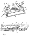
- a loading space of a motor vehicle in the present case a station wagon or a passenger car, has a loading space functional device, which in the illustrated embodiment is designed as a load compartment cover 1, 5.
- the load compartment cover has a cassette housing 5, shown only schematically, in which a flexible sheet 1 is compact, preferably rolled up on a winding shaft.
- the cassette housing 5 is - seen in the normal direction of travel of the motor vehicle - positioned in a front area of the loading space immediately behind a backrest assembly of a rear bench seat.
- the sheet 1 is from the compact rest position within the cassette housing 5 to a vehicle rear just below a vehicle's edge, it can be extended approximately horizontally to the rear.
- the fabric 1 has a pull-out strip 2, which is arranged to be longitudinally displaceable in the region of its opposite sides in each case in a guide rail 4 serving as a functional track.
- the pull-out strip 2 is associated with a dimensionally stable contours 3, which is firmly connected to the Auszugsang 2 and the sheet 1.
- the contour part 3 serves to compensate for the correspondingly curved inner contour of the tailgate in the region of a tailgate and to cover this rear end region of the cargo space in the extended state of the cargo area cover.
- a handle opening is provided, which also - as in Fig. 3 can be seen - is associated with an actuating element described in more detail below.
- Each guide rail 4 is fastened in the region of opposite side walls of the loading space.
- Each guide rail 4 has an approximately C-shaped cross-sectional profile which is open towards the middle of the load compartment.
- the respective front end of the extension strip 2 is used, which is slidably movable within the respective guide rail 4.
- a pair of receiving pockets 6 are arranged approximately in a middle extension position of the fabric 1 and the other pair of receiving pockets 6 in a rear-side extended end position of the fabric 1 in each pair of guide rails at the same level opposite each other in pairs serving as receiving areas receiving pockets 6 is.
- the on-receiving pockets 6 are arranged below the respective guide rail 4, wherein the receiving pockets 6 are open towards the center of the load and rest against the respective side wall of the cargo space.
- Each receiving pocket 6 has a passage opening 7 in the guide rail 4 in the region of its upper side. Through this passage 7 protrudes serving as a blocking element pawl 9 of an insertable into the respective receiving pocket 6 blocking module 8, as long as the pawl 9 is in its blocking position.
- the receiving pocket could be integrally formed on the respective guide rail 4 or attached as separate components to this.
- Each receiving pocket 6 has an approximately rectangular free cross section into which a cuboid block module 8 can be inserted horizontally from the middle of the load compartment.
- the blocking module 8 is matched in its cuboid shape to the receiving space within each receiving pocket 6 such that the respective blocking module 8 can be inserted flush into the receiving pocket 6 and can be detachably fastened in the receiving pocket 6.
- a parallelepiped housing 10 of the blocking module 8 has two groove-like angular recesses 12, which can be plugged onto non-illustrated angle webs within the receiving pockets 6 when inserting the blocking module 8.
- latching means or otherwise designed fastening means are provided which fix the blocking module in its inserted state in the respective receiving pocket.
- the latching means or the differently shaped fastening means are designed to be detachable, in order to enable a renewed disassembly of the blocking module.
- the blocking modules 8 occur - like the receiving pockets 6 - in pairs in function. For the two guide rails 4 thus at least two mutually opposite blocking modules are provided.
- the housing 10 is designed like a frame.
- the housing 10 as well as all other parts of the blocking module 8 are mirror-symmetrical to a - based on the functional state of the blocking module - vertical central longitudinal plane of the blocking module 8 executed. This makes it possible to use each blocking module as a common part both left and right in the opposite guide rails 4. All blocking modules 8 are thus made identical and can be used either left or right side.
- the side walls of the blocking module 8 are formed by releasable cover 11, as can be seen with reference to FIG.
- the pawl 9 protrudes through a recess 13 in the region of an upper side of the housing 10 and is mounted in the interior of the housing 10 on a transverse bushing 14, which additionally serves to fasten the lid 11, pivotally mounted about an aligned in the operating position in the vehicle transverse direction axis ,
- a bearing receptacle by means of which the pawl 9 is held on the transverse bushing 14, designed as a slot 15, in addition to a limited longitudinal movement of the pawl 9 in the vehicle longitudinal direction, i. parallel to the respective guide rail 4, to allow the recess 13 is greater in length than the corresponding longitudinal extent of the pawl 9 executed in order not to restrict the predetermined by the slot 15 limited longitudinal movement of the pawl 9.
- the pawl 9 is also provided with a stop web 18 which rests in a lower edge region of the recess 13 on an inner housing wall of the housing 10.
- the stop web 18 is stretched so far that even with a pawl 9 located in a rear end position relative to the housing 10, a bearing in the region of the underside of the recess 13 results.
- the pawl 9 is also acted upon obliquely from below by serving as a spring means compression spring 16 in the direction of its blocking position.
- the compression spring 16 serves to hold the pawl 9 in its blocking position. Since the compression spring 16 is oriented both obliquely downward and obliquely forward, it serves for securing and supporting the pawl 9 in its upwardly pivoted blocking position. On the other hand, the compression spring 16 pushes the pawl 9 in the unloaded state also in the fitting at a rear edge region of the recess 13 rear end position.
- the pawl 9 is provided in its blocking position shown in Fig. 2 with an approximately vertically upwardly directed stop surface, which projects into the guide rail 4.
- the top of the pawl 9 drops obliquely in the vehicle longitudinal direction forward, so that there is a run-on slope according to FIG. 2, as soon as a side region of the pull-out strip 2 passes over the pawl 9 from the front.
- the compression spring 16 presses the pawl 9 back into the blocking position.
- the pawl 9 is designed slightly different.
- the blocking module 8a according to FIG. 3 of the embodiment according to FIGS. 1 and 2 corresponds to its basic construction and its basic function.
- a control element as well as an actuating element can therefore likewise be used to release the pawl 9 according to FIGS be used as in the embodiment of FIG. 3. The following description therefore applies to both embodiments.
- Each control element 20 is formed by a control lever, which is arranged non-rotatably on a running through the length of the extension rail 2a control shaft 19.
- the control shaft 19 is pivotally mounted within the pull-out strip 2a about an axis of rotation extending in the vehicle transverse direction.
- the actuating element B lever-like In a central region engages on the control shaft 19, the actuating element B lever-like, so that a force exerted by the actuator B on the control shaft 19 pivotal movement leads to a corresponding pivoting or tilting movement of both controls 20 at the opposite ends of the extension rail 2a.
- the control shaft 19 and / or the lever-like actuator B is assigned in a manner not shown a return spring which holds the control lever 20 in the unloaded position of the actuating element B in an upper, aligned with the contour of the drawer strip 2a rest position.
- the control levers 20 are arranged relative to the pull-out strip 2, 2a or relative to the pawl 9, 9a (not visible in FIG. 3), that the respective control lever 20 acts on the run-on slope of the respective pawl 9 as soon as it is pressed down becomes. As a result, the pawl 9 is pressed down and releases the respective front end of the extension strip 2, 2 a for longitudinal movement and thus a return movement of the fabric 1 free.
- a pawl 9b within a blocking module 8b serves to block or release a frontal end of a pull-out strip 2b in a guide rail 4.
- the pawl 9b is merely pivotally mounted within the blocking module 8b, without the pawl 9b additionally having an axial mobility.
- the entire blocking module 8b is limited longitudinally movable parallel below the guide rail 4.
- an unspecified Receiving pocket provided with a longitudinal extent which is greater than a longitudinal extent of the housing of the blocking module 8b.
- a spring means 26 is provided within the receiving pocket, which performs a damping and tolerance compensation function according to the previously described embodiment of the compression spring 16 of FIG. 2.
- the pawl 9b is associated with a return spring 27, which is aligned without axial component only in the vehicle vertical direction.
- a return spring 27 is provided within the pull bar 2b, provided at the opposite ends each have a control lever 21 is.
- a vertically movable slide 22 is mounted, which acts on a stop pin 28 of a release latch 24.
- the release latch 24 is pivotally mounted about a pivot axis 23 which is aligned parallel to the pivot axis of the pawl 9b.
- the pivoting sense of the trigger pawl 24 is opposite to the pivoting sense of the pawl 9b.
- the pawl 9b has a control extension 25 which cooperates with a control lug of the trigger pawl 24 as soon as the trigger pawl 24 is actuated by means of the control lever 21.
- the release latch 24 is assigned in a manner not shown a return spring, which returns the trigger pawl 24 and thus also the slider 22 in the unloaded state to the starting position shown in FIG.
- the release pawl 24 as well as the pawl 9b are returned to their upper initial position (FIG. 6) by the corresponding return springs. If now the pull-out strip 2b is pulled out again and the pawl 9b passes over, the functional position according to FIG. 6 is reached again, so that the release or release process can be repeated.
- FIGS. 7 to 9 The embodiment of a load compartment function device according to FIGS. 7 to 9 is likewise part of a load compartment cover, as has already been described in detail with reference to the preceding embodiments.
- the disclosure of the cargo compartment function device according to FIGS. 7 to 9 reference is made to the disclosure of the embodiments described with reference to FIGS. 1 to 6.
- Functionally identical components are provided with the same reference numerals with the addition of the letter c.
- guide rails 4c are provided on opposite side walls of the loading space, to which receiving pockets for releasably receiving blocking modules 8c are assigned.
- a pull-out strip 2c of the luggage compartment cover is formed by a dimensionally stable contour plate which extends across the width of the load compartment cover and at the opposite end face areas as a guide element in each case integrally formed on the contour plate, designed as ledge or flat profile guide extension.
- the height of the guide rail 4c is designed so that the respective guide extension of the contour plate axially slidably displaceable in a corresponding groove of the guide rail 4c.
- each blocking module has a support nose 30, which is designed as an undercut with respect to a wedge-shaped inclined contact surface 36 of the respective guide extension of the extension strip 2c. It can be clearly seen from FIGS. 8 and 9 that the support lug 30 supports the wedge-shaped abutment surface 36 both axially and provides additional support radially above the wedge surface in order to prevent upward sliding of the guide extension of the extension ledge 2c.
- the design of the undercut and the wedge-shaped contact surface 36 of FIG. 9 can be easily removed.
- the pull-out strip In order to unlock the pawl 9c and release the guide extensions of the pull-out strip 2c for longitudinal movement within the guide rails 4c, the pull-out strip, ie the contour plate, is slightly tilted or tilted about its longitudinal axis extending in the vehicle transverse direction, thereby inevitably also the guide extension into the Guide rail 4c is pressed obliquely upwards.
- the necessary space for a tilting or pivoting movement of the extension strip and the guide extensions upward is formed by recesses 37 at the level of each blocking module, which are arranged in the guide rail 4c of FIG. 9 or 7.
- the support lug 30 serves to ensure that the guide extensions and thus the extension strip or the contour plate are not already pivoted upward by the weight of the contour plate and thus come free.
- the support nose 30 in conjunction with the wedge-shaped contact surface 36 forms radially to the longitudinal axis of movement of the drawer up a support that is overcome only by larger loads, such as in particular a manual pressure from above the contour plate.
- the pawl 9c is held by spring force in its blocking position and is mounted axially movable according to the embodiments described above.
- a stop 35 is provided in extension of the pawl 9c, which is supported on the inside of the blocking module.
- the blocking module has attachment lugs 31, 32 which can be inserted into corresponding recesses in the region of the guide rail from the side and thus ensure the releasable attachment of the blocking module in the region of the guide rail 4c.
- the guide rails 4c each have at the height of the recesses 37 only recesses in the region of a bottom surface of the guide rail of the respective guide rail 4c, in which the respective blocking module 8c with its fastening lugs 31, 32 from the side can be inserted.
- the blocking module 8c has a lid 11 c, which is fastened by means of locking lugs 33 on corresponding latching recesses 34 of a housing of the blocking module 8c.
- the cover 11c is integrally hinged to the blocking module 8c by means of a film hinge in the region of a lower side of the housing and is thus held captive on the blocking module 8c.
Landscapes
- Engineering & Computer Science (AREA)
- Mechanical Engineering (AREA)
- Vehicle Step Arrangements And Article Storage (AREA)
Description
- Die Erfindung betrifft eine Laderaumfunktionseinrichtung mit wenigstens einer Funktionsspur, in der wenigstens ein Funktionselement durch wenigstens zwei Funktionspositionen begrenzt längsbeweglich angeordnet ist.
- Eine Laderaumfunktionseinrichtung für ein Kraftfahrzeug ist in Form einer horizontal ausziehbaren Laderaumabdeckung allgemein bekannt. Die Laderaumabdeckung weist ein flexibles Flächengebilde auf, das auf einer Wickelwelle auf- und abrollbar angeordnet ist. An seinem in Auszugrichtung vorderen Endbereich weist das Flächengebilde eine Auszugleiste auf, die mit ihren gegenüberliegenden Stirnenden in jeweils einer Führungsschiene längsverschiebbar gehalten ist.
- Die US 6,402,217 B1 zeigt eine Laderaumabtrennung mit einem flexiblen Rollo, das in einem ersten Endbereich an einer federvorbelasteten Wickelwelle befestigt ist und an einem zweiten freien Endbereich mit einer quer zu einer Fahrzeuglängsrichtung verlaufenden Auszugstange versehen ist. Für eine Führung der Auszugstange in einem Laderaum eines Kraftfahrzeugs sind beidseitig in Laderaurnwänden des Laderaums jeweils im wesentlichen horizontal verlaufende Führungsschienenabschnitte vorgesehen, die für eine Führung von Endbereichen der Auszugstange in horizontaler Richtung vorgesehen sind. An die horizontal verlaufenden Führungsschienenabschnitte schließen jeweils beidseitig im Wesentlichen vertikal verlaufende Führungsschienenabschnitte an, die sich längs einer Dachsäule des Kraftfahrzeugs erstrecken. An einem Übergang zwischen dem horizontalen Führungsschienenabschnitt und dem vertikalen Führungsschienenabschnitt ist jeweils eine Riegeleinrichtung vorgesehen, die eine Arretierung der Auszugschiene einer horizontalen Funktionsposition ermöglicht. Die Riegeleinrichtung, die jeweils ein integraler Bestandteil der Führungsschienenabschnitte ist, ermöglicht durch eine Hebeleinrichtung, die von einer Kofferraumklappe des Kraftfahrzeugs ansteuerbar ist, eine Umlenkung der Auszugstange von dem horizontalen Führungsschienenabschnitt in den vertikalen Führungsschienenabschnitt. Damit kann eine Kornfortfunktion erzielt werden, bei der das Rollo automatisch bei Öffnen der Kofferraumklappe aus der horizontalen Funktionsposition in eine Komfortposition längs der vertikalen Führungsschienenabschnitte bewegt wird und somit einen komfortablen Zugang zum Laderaum ermöglicht
- Aus der DE 200 13 722 U1 geht eine Laderaumabdeckung hervor, bei der eine flexible Werkstoffbahn mit einem endseitig an einem freien Endbereich angebrachten Endbord versehen ist Das Endbord weist ein Griffteil auf, das mit einer Welle, die sich über die Breite des Laderaums erstreckt, gekoppelt ist. Endseitig sind an der Welle jeweils Führungskörper angebracht, die in fahrzeugfesten Führungsschienen verschiebbar angebracht sind und die mit schwenkbeweglichen und federvorbelasteten Sperrzungen versehen sind. Die dem Griffteil zugeordnete Welle ist drehbar in den Führungskörpern gelagert und ist drehfest mit den Sperrzungen verbunden. Die Sperrzungen sind für einen formschlüssigen Eingriff in Aussparungen vorgesehen, die in den Führungsschienen angeordnet sind und die eine Arretierung des Endbords und der damit verbundenen flexiblen Werkstoffbahn in unterschiedlichen Funktionsstellungen ermöglicht.
- Die EP 0 565 220 A1 beschreibt eine Laderaumabdeckung mit einem flexiblen Sichtschutz, der auf einer federvorgespannten Wickelwelle aufrollbar ist und der an einem freien Ende mit einer Auszugstange versehen ist. Die Auszugstange ist für einen Eingriff in seitlich an Laderaumwänden vorgesehene Führungsschienen vorgesehen, die für eine Festlegung des Sichtschutzes in vorgegebenen Stellungen gestaltet sind. Dazu sind die Führungsschienen mit verschieden gestalteten Ausnehmungen oder Ausbuchtungen versehen, in die die Auszugstange eingehängt werden kann, um unterschiedliche, aber fest vorgegebene Arretierungsposition einzunehmen.
- Aus der DE 199 44 948 C2 ist es bekannt, die Stirnenden der Auszugleisten mit jeweils einem Mitnehmer in der jeweiligen Führungsschiene in Verbindung zu bringen, wobei der Mitnehmer in jeder Führungsschiene durch einen Antrieb längsverschiebbar geführt ist Ein solcher Mitnehmer stellt ein Funktionselement im Sinne der Erfindung dar. Die Blockierung der Ausziehleiste und damit des Flächengebildes in unterschiedlichen Positionen längs der Führungsschienen erfolgt durch entsprechendes Stillsetzen der Antriebseinrichtung für die Mitnehmer.
- Aufgabe der Erfindung ist es, eine Laderaumfunktionseinrichtung der eingangs genannten Art zu schaffen, die einen variablen Einsatz ermöglicht.
- Diese Aufgabe wird durch die Merkmale des Anspruchs 1 gelöst. An wenigstens einer Funktionsposition der Funktionsspur ist ein Aufnahmebereich zum lösbaren Befestigen eines Blockiermoduls angeordnet das wenigstens ein Blockierelement aufweist, das zwischen einer das Funktionselement fixierenden Blockierposition und einer das Funktionselement für eine Längsbewegung freigebenden Ruheposition beweglich angeordnet ist. Dadurch ist es möglich, der wenigstens einen Funktionsposition wahlweise ein Blockiermodul zuzuordnen oder nicht. Je nach Einsatzzweck kann somit diese Funktionsposition als Blockierposition oder auch als nicht arretierbare Funktionsposition gestaltet werden.
- In Ausgestaltung der Erfindung sind über die Länge der Funktionsspur verteilt mehrere Aufnahmebereiche angeordnet, an denen jeweils ein Blockiermodul befestigbar ist. Dadurch ist es möglich, je nach Funktionsund Einsatzzweck wahlweise eine oder mehrere, als Zwischen- oder als Endpositionen gestaltete Funktionspositionen mit einer entsprechenden Blockierfunktion auszurüsten.
- In weiterer Ausgestaltung der Erfindung ist jeder Aufnahmebereich tasehen- oder wannenartig ausgebildet. Gemäß der erfindung ist das Blockiemodul derart korrespondierend block- oder rahmenförmig gestaltet, dass es bündig und/oder formschlüssig in den Aufnahmebereich einsetzbar ist. Vorzugsweise sind zwei Funktionsspuren als Führungsschienen an gegenüberliegenden Seitenwandungen eines Laderaumes vorgesehen. Bei einer derartigen Ausführung sind die Aufnahmebereiche vorzugsweise zur Laderaummitte hin offen, so dass das entsprechende Blockiermodul vom Laderaum her in den jeweiligen Aufnahmebereich einsetzbar ist.
- In weiterer Ausgestaltung der Erfindung sind lösbare Rastmittel vorgesehen, um das Blockiermodul in dem Aufnahmebereich zu fixieren. Dies ist eine besonders einfache und funktionssichere mechanische Ausführung.
- In weiterer Ausgestaltung der Erfindung ist das Blockiermodul spiegelsymmetrisch zu seiner hochgerichteten Mittellängsebene ausgebildet. Dadurch ist es möglich, das Blockiermodul Funktionsspuren auf gegenüberliegenden Fahrzeugseiten zuzuordnen, ohne für die linke bzw. rechte Seite - auf eine Laderaumabdeckung bezogen - unterschiedliche Blockiermodule zu benötigen. Die Blockiermodule für beide Seiten können somit baugleich ausgeführt sein. Die hochgerichtete Mittellängsebene des Blockiermoduls ist in einer Funktionsstellung des Blockiermoduls vorzugsweise vertikal ausgerichtet und entspricht insbesondere der Ebene, in der das Blockierelement beweglich gelagert ist.
- In weiterer Ausgestaltung der Erfindung ist das Blockierelement in Richtung seiner Blockierposition mit einem Federmittel kraftbeaufschlagt. Dadurch befindet sich das Blockierelement automatisch in seiner Blockierposition, solange eine Gegenkraft auf das Blockierelement ausgeübt wird. Vorzugsweise ist das Blockierelement als schwenkbeweglich gelagerte Sperrklinke ausgeführt.
- In weiterer Ausgestaltung der Erfindung ist das Blockierelement in Bewegungsrichtung des Funktionselementes begrenzt axial beweglich angeordnet. Dadurch ist ein Toleranzausgleich möglich, um eine Blockierung des Funktionselementes auch dann sicher erzielen zu können, wenn das Funktionselement sich nicht exakt in der entsprechend definierten Funktionsposition befindet.
- In weiterer Ausgestaltung der Erfindung ist dem Blockierelement ein die axiale Beweglichkeit bremsendes Dämpferelement, insbesondere ein Federelement, zugeordnet. Dadurch wird das Blockierelement unter Vorspannung gehalten, so dass auch bei toleranzbehafteter Funktionsposition des Funktionselementes eine sichere Anlage des Blockierelementes an dem Funktionselement erzielt wird.
- In weiterer Ausgestaltung der Erfindung ist ein Steuerelement zum Überführen des Blockierelementes aus seiner Blockierposition in die Ruheposition vorgesehen. Vorzugsweise ist ein manuell betätigbares Steuerelement vorgesehen. Falls das Funktionselement Teil einer Auszugleiste seiner Laderaumabdeckung ist, so ist es möglich, im Bereich der Auszugleiste der Laderaumabdeckung ein manuell bedienbares Betätigungselement vorzusehen, das das Steuerelement in entsprechender Weise bewegt. Alternativ ist es möglich, das Funktionselement selbst begrenzt beweglich zu lagern, um so direkt über das Funktionselement das Blockierelement ansteuern und in seine Ruheposition überführen zu können.
- Weitere Vorteile und Merkmale der Erfindung ergeben sich aus den Ansprüchen sowie aus der nachfolgenden Beschreibung bevorzugter Ausführungsbeispiele der Erfindung, die anhand der Zeichnungen dargestellt sind.
- Fig. 1
- zeigt in perspektivischer Darstellung eine Ausführungsform einer erfindungsgemäßen Laderaumfunktionseinrichtung,
- Fig. 2
- in vergrößerter, perspektivischer Darstellung ein Blockiermodul für die Laderaumfunktionseinrichtung nach Fig. 1,
- Fig. 3
- in vergrößerter, perspektivischer und teilweise aufgebrochener Darstellung einen Ausschnitt einer weiteren Laderaumfunktionseinrichtung im Bereich eines Blockiermoduls,
- Fig. 4
- in schematischer Darstellung einen Ausschnitt einer weiteren Laderaumfunktionseinrichtung, ähnlich Fig. 1 im Bereich eines Blockiermoduls,
- Fig. 5 und 6
- das Blockiermodul nach Fig. 4 in unterschiedlichen Funktionsstellungen,
- Fig. 7
- in perspektivischer, schematischer Darstellung eine Ausführungsform einer erfindungsgemäßen Laderaumfunktionseinrichtung als Ausschnitt ähnlich Fig. 3,
- Fig. 8
- in vergrößerter, perspektivischer Darstellung eine weitere Ausführungsform eines Blockiermoduls und
- Fig. 9
- in vergrößerter Längsschnittdarstellung die Blockierung eines Funktionselementes mittels einer Sperrklinke des Blockiermoduls.
- Ein Laderaum eines Kraftfahrzeugs, vorliegend eines Kombi-Personenkraftwagens oder einer Großraumlimousine, weist eine Laderaumfunktionseinrichtung auf, die beim dargestellten Ausführungsbeispiel als Laderaumabdeckung 1, 5 ausgeführt ist. Die Laderaumabdeckung weist ein lediglich schematisch dargestelltes Kassettengehäuse 5 auf, in dem ein flexibles Flächengebilde 1 kompakt, vorzugsweise auf einer Wickelwelle aufgerollt, abgelegt ist. Das Kassettengehäuse 5 ist - in normaler Fahrtrichtung des Kraftfahrzeugs gesehen - in einem vorderen Bereich des Laderaumes unmittelbar hinter einer Rückenlehnenanordnung einer Fondsitzbank positioniert. Das Flächengebilde 1 ist aus der kompakten Ruheposition innerhalb des Kassettengehäuses 5 zu einem Fahrzeugheck knapp unterhalb einer Fahrzeugbordkante etwa horizontal nach hinten ausziehbar. An einem in Ausziehrichtung vorderen Stirnende weist das Flächengebilde 1 eine Auszugleiste 2 auf, die im Bereich ihrer gegenüberliegenden Seiten in jeweils einer als Funktionsspur dienenden Führungsschiene 4 längsverschiebbar angeordnet ist. Der Auszugleiste 2 ist ein formstabiles Konturteil 3 zugeordnet, das fest mit der Auszugsleiste 2 und dem Flächengebilde 1 verbunden ist. Das Konturteil 3 dient dazu, im Bereich einer Heckklappe die entsprechend gewölbte Innenkontur der Heckklappe auszugleichen und im ausgezogenen Zustand der Laderaumabdeckung diesen heckseitigen Endbereich des Laderaumes abzudecken. In einem mittleren Bereich des Konturteiles 3 ist eine Grifföffnung vorgesehen, der zudem - wie in Fig. 3 erkennbar ist - ein nachfolgend näher beschriebenes Betätigungselement zugeordnet ist.
- Die beiden Führungsschienen 4 sind im Bereich gegenüberliegender Seitenwandungen des Laderaumes befestigt. Jede Führungsschiene 4 weist ein etwa C-förmiges Querschnittsprofil auf, das jeweils zur Laderaummitte hin offen ist. In die offene Seite jeder Führungsschiene 4 ist das jeweilige Stirnende der Auszugleiste 2 eingesetzt, das gleitbeweglich innerhalb der jeweiligen Führungsschiene 4 verschiebbar ist.
- In beiden Führungsschienen sind einander auf gleicher Höhe gegenüberliegend jeweils paarweise insgesamt vier als Aufnahmebereiche dienende Aufnahmetaschen 6 zugeordnet, wobei ein Paar von Aufnahmetaschen 6 etwa in einer mittleren Ausziehposition des Flächengebildes 1 und das andere Paar von Aufnahmetaschen 6 in einer heckseitig ausgezogenen Endposition des Flächengebildes 1 angeordnet ist. Die Auf-nahmetaschen 6 sind unterhalb der jeweiligen Führungsschiene 4 angeordnet, wobei die Aufnahmetaschen 6 zur Laderaummitte hin offen sind und an der jeweiligen Seitenwandung des Laderaumes anliegen. Jede Aufnahmetasche 6 weist im Bereich ihrer Oberseite eine Durchtrittsöffnung 7 in die Führungsschiene 4 hinein auf. Durch diese Durchtrittsöffnung 7 ragt eine als Blockierelement dienende Sperrklinke 9 eines in die jeweilige Aufnahmetasche 6 einsetzbaren Blockiermoduls 8 hindurch, solange die Sperrklinke 9 sich in ihrer Blockierposition befindet. Die Aufnahmetasche könnte einstückig an der jeweiligen Führungsschiene 4 angeformt oder auch als separate Bauteile an dieser befestigt sein.
- Jede Aufnahmetasche 6 weist einen etwa rechteckigen freien Querschnitt auf, in den ein quaderartiges Blockiermodul 8 von der Laderaummitte her horizontal einsetzbar ist. Das Blockiermodul 8 ist in seiner Quaderform derart auf den Aufnahmeraum innerhalb jeder Aufnahmetasche 6 abgestimmt, dass das jeweilige Blockiermodul 8 bündig in die Aufnahmetasche 6 einsetzbar und in dieser lösbar befestigbar ist.
- Beim dargestellten Ausführungsbeispiel weist ein quaderartiges Gehäuse 10 des Blockiermoduls 8 zwei nutartige Winkelaussparungen 12 auf, die auf nicht näher dargestellte Winkelstege innerhalb der Aufnahmetaschen 6 beim Einsetzen des Blockiermoduls 8 aufsteckbar sind. In nicht näher dargestellter Weise sind Rastmittel oder anders gestaltete Befestigungsmittel vorgesehen, die das Blockiermodul in seinem eingesetzten Zustand in der jeweiligen Aufnahmetasche fixieren. Die Rastmittel bzw. die anders gestalteten Befestigungsmittel sind lösbar ausgeführt, um eine erneute Demontage des Blockiermoduls zu ermöglichen. Auch die Blockiermodule 8 treten - wie die Aufnahmetaschen 6 - jeweils paarweise in Funktion. Für die beiden Führungsschienen 4 sind somit wenigstens zwei einander gegenüberliegende Blockiermodule vorgesehen.
- Das Gehäuse 10 ist rahmenartig gestaltet. Das Gehäuse 10 wie auch alle weitere Teile des Blockiermoduls 8 sind spiegelsymmetrisch zu einer - auf den Funktionszustand des Blockiermoduls bezogen - vertikalen Mittellängsebene des Blockiermoduls 8 ausgeführt. Dadurch ist es möglich, jedes Blockiermodul als Gleichteil sowohl links- als auch rechtsseitig in den gegenüberliegenden Führungsschienen 4 einzusetzen. Alle Blockiermodule 8 sind somit identisch ausgeführt und können wahlweise links- oder rechtsseitig eingesetzt werden. Die Seitenwandungen des Blockiermoduls 8 werden durch lösbare Deckel 11 gebildet, wie anhand der Fig. 2 erkennbar ist.
- Die Sperrklinke 9 ragt durch eine Aussparung 13 im Bereich einer Oberseite des Gehäuses 10 hindurch und ist im Inneren des Gehäuses 10 auf einer Querbuchse 14, die zusätzlich zur Befestigung des Deckels 11 dient, um eine in der Funktionsposition in Fahrzeugquerrichtung ausgerichtete Achse zum einen schwenkbeweglich gelagert. Zum anderen ist eine Lageraufnahme, mittels der die Sperrklinke 9 auf der Querbuchse 14 gehalten ist, als Langloch 15 ausgeführt, um zusätzlich eine begrenzte Längsbeweglichkeit der Sperrklinke 9 in Fahrzeuglängsrichtung, d.h. parallel zu der jeweiligen Führungsschiene 4, zu ermöglichen Die Aussparung 13 ist in ihrer Länge größer als die korrespondierende Längserstreckung der Sperrklinke 9 ausgeführt, um die durch das Langloch 15 vorgegebene begrenzte Längsbeweglichkeit der Sperrklinke 9 nicht einzuschränken. Die Sperrklinke 9 ist zudem mit einem Anschlagsteg 18 versehen, der in einem unteren Randbereich der Aussparung 13 an einer inneren Gehäusewandung des Gehäuses 10 anliegt. Der Anschlagsteg 18 ist so weit längserstreckt, dass sich auch bei einer sich in einer hinteren Endposition befindenden Sperrklinke 9 relativ zu dem Gehäuse 10 eine Anlage im Bereich der Unterseite der Aussparung 13 ergibt.
- Die Sperrklinke 9 ist zudem schräg von unten her durch eine als Federmittel dienende Druckfeder 16 in Richtung ihrer Blockierposition kraftbeaufschlagt. Die Druckfeder 16 dient dazu, die Sperrklinke 9 in ihrer Blockierposition zu halten. Da die Druckfeder 16 sowohl schräg nach unten als auch schräg nach vorne ausgerichtet ist, dient sie zum einen zur Sicherung und Stützung der Sperrklinke 9 in ihrer nach oben verschwenkten Blockierposition. Zum anderen drückt die Druckfeder 16 die Sperrklinke 9 im unbelasteten Zustand auch in die an einem hinteren Randbereich der Aussparung 13 anliegende rückseitige Endposition.
- Die Sperrklinke 9 ist in ihrer in Fig. 2 dargestellten Blockierposition mit einer etwa vertikal nach oben ausgerichteten Anschlagfläche versehen, die in die Führungsschiene 4 hineinragt. Zudem fällt die Oberseite der Sperrklinke 9 in Fahrzeuglängsrichtung nach vorne schräg ab, so dass sich eine Anlaufschräge gemäß Fig. 2 ergibt, sobald von vorne her ein Seitenbereich der Auszugleiste 2 die Sperrklinke 9 überfährt. Bei einem Ausziehen der Auszugleiste 2 und des Flächengebildes 1 bewirkt das Überfahren der Sperrklinke 9 zwangsläufig ein Nachuntendrücken der Sperrklinke 9 in eine Freigabeposition. Sobald die Auszugleiste 2 die Sperrklinke 9 überfahren hat, drückt die Druckfeder 16 die Sperrklinke 9 zurück in die Blockierposition. Wenn nun eine Rückholfederanordnung innerhalb des Kassettengehäuses 5 das Flächengebilde 1 wieder zurückziehen will, sobald die manuelle Zugkraft auf die Auszugleiste 2 weggenommen ist, schlägt die Auszugleiste 2 mit ihren Stirnendbereichen zwangsläufig an der jeweiligen Anlauffläche der Sperrklinke 9 an und wird in dieser Funktionsposition blockiert.
- Um die jeweilige Sperrklinke 9 jedes Blockiermoduls 8 in den gegenüberliegenden Führungsschienen 4 bei Bedarf wieder lösen zu können, um einen Rückzug des Flächengebildes 1 in seine kompakte Ruheposition innerhalb des Kassettengehäuses 5 zu ermöglichen, ist gemäß Fig. 3 jeder Sperrklinke ein Steuerelement zugeordnet, das durch ein manuell bedienbares Betätigungselement B beweglich ist. Bei der Ausführungsform nach Fig. 3 ist die Sperrklinke 9 geringfügig anders gestaltet. Von ihrem grundsätzlichen Aufbau und ihrer grundsätzlichen Funktion her entspricht jedoch das Blockiermodul 8a gemäß Fig. 3 der Ausführungsform nach den Fig. 1 und 2. Ein Steuerelement wie auch ein Betätigungselement können daher in gleicher Weise zum Lösen der Sperrklinke 9 nach Fig. 1 und 2 eingesetzt werden wie bei der Ausführungsform nach Fig. 3. Die nachfolgende Beschreibung gilt daher für beide Ausführungsformen.
- Jedes Steuerelement 20 wird durch einen Steuerhebel gebildet, der an einer durch die Länge der Auszugleiste 2a verlaufenden Steuerwelle 19 drehfest angeordnet ist. Die Steuerwelle 19 ist innerhalb der Auszugleiste 2a um eine in Fahrzeugquerrichtung verlaufende Drehachse schwenkbeweglich gelagert. In einem mittleren Bereich greift an der Steuerwelle 19 das Betätigungselement B hebelartig an, so dass eine durch das Betätigungselement B auf die Steuerwelle 19 ausgeübte Schwenkbewegung zu einer korrespondierenden Schwenk- oder Kippbewegung beider Steuerelemente 20 an den gegenüberliegenden Stirnenden der Auszugleiste 2a führt. Dadurch, dass beide Steuerelemente 20, d.h. die Steuerhebel, an einer gemeinsamen Steuerwelle 19 befestigt sind, wird zwangsläufig eine synchrone Bewegung der gegenüberliegenden Steuerhebel 20 bewirkt. Der Steuerwelle 19 und/oder dem hebelartigen Betätigungselement B ist in nicht näher dargestellter Weise eine Rückstellfeder zugeordnet, die die Steuerhebel 20 in der nicht belasteten Position des Betätigungselementes B in einer oberen, mit der Kontur der Auszugleiste 2a fluchtenden Ruhelage hält. Die Steuerhebel 20 sind so relativ zu der Auszugleiste 2, 2a bzw. relativ zu der Sperrklinke 9, 9a angeordnet (in Fig. 3 nicht erkennbar), dass der jeweilige Steuerhebel 20 auf die Anlaufschräge der jeweiligen Sperrklinke 9 einwirkt, sobald er nach unten gedrückt wird. Hierdurch wird die Sperrklinke 9 nach unten gedrückt und gibt das jeweilige Stirnende der Auszugleiste 2, 2a für eine Längsbewegung und damit eine Rückholbewegung des Flächengebildes 1 frei.
- Bei der Ausführungsform nach den Fig. 4 bis 6 dient eine Sperrklinke 9b innerhalb eines Blockiermoduls 8b dazu, ein stirnseitiges Ende einer Auszugleiste 2b in einer Führungsschiene 4 zu blockieren bzw. freizugeben. Bei dieser Ausführungsform ist die Sperrklinke 9b innerhalb des Blockiermoduls 8b lediglich schwenkbeweglich gelagert, ohne dass die Sperrklinke 9b zusätzlich eine Axialbeweglichkeit aufweist. Allerdings ist das gesamte Blockiermodul 8b parallel unterhalb der Führungsschiene 4 begrenzt längsbeweglich. Hierzu ist eine nicht näher bezeichnete Aufnahmetasche mit einer Längserstreckung versehen, die größer ist als eine Längserstreckung des Gehäuses des Blockiermoduls 8b. Zudem ist innerhalb der Aufnahmetasche ein Federmittel 26 vorgesehen, das eine Dämpfungs- und Toleranzausgleichsfunktion durchführt entsprechend der zuvor beschriebenen Ausführung der Druckfeder 16 gemäß Fig. 2. Der Sperrklinke 9b ist eine Rückstellfeder 27 zugeordnet, die ohne Axialkomponente lediglich in Fahrzeughochrichtung ausgerichtet ist. Um auch die Sperrklinke 9b aus ihrer die Auszugleiste 2b fixierenden Blockierposition gemäß Fig. 6 in eine Freigabeposition zu überführen, ist analog der Ausführungsform nach Fig. 3 eine nicht näher bezeichnete Steuerwelle innerhalb der Auszugleiste 2b vorgesehen, an deren gegenüberliegenden Stirnenden jeweils ein Steuerhebel 21 vorgesehen ist. Innerhalb des Blockiermoduls 8b ist ein vertikal beweglicher Schieber 22 gelagert, der auf einen Anschlagzapfen 28 einer Auslöseklinke 24 wirkt. Die Auslöseklinke 24 ist um eine Schwenkachse 23, die parallel zur Schwenkachse der Sperrklinke 9b ausgerichtet ist, schwenkbeweglich gelagert. Allerdings ist der Schwenksinn der Auslöseklinke 24 entgegengesetzt zum Schwenksinn der Sperrklinke 9b. Die Sperrklinke 9b weist einen Steuerfortsatz 25 auf, der mit einer Steuernase der Auslöseklinke 24 zusammenwirkt, sobald die Auslöseklinke 24 mittels des Steuerhebeis 21 betätigt wird. Der Auslöseklinke 24 ist in nicht näher dargestellter Weise eine Rückstellfeder zugeordnet, die die Auslöseklinke 24 und damit auch den Schieber 22 in unbelastetem Zustand in die Ausgangslage gemäß Fig. 4 zurückführt.
- Sobald nun in der arretierten Blockierposition der Auszugleiste 2b gemäß Fig. 6 für ein Zurückziehen des Flächengebildes in seine kompakte Ruheposition eine Freigabe der Auszugleiste 2b erforderlich wird, wird manuell mittels der Kraftbeaufschlagung eines Betätigungselementes B analog Fig. 3 die Steuerwelle verdreht, wodurch die Steuerhebel 21 (Fig. 6) die Schieber 22 nach unten drücken (Fig. 5). Dadurch wird die Auslöseklinke 24 zwangsläufig nach unten verschwenkt. Gleichzeitig drückt die Auslöseklinke 24 über den Steuerfortsatz 25 auch die Sperrklinke 9b nach unten, so dass die Sperrklinke 9b sich aus der Führungsschiene 4 nach unten zurückzieht. Wie anhand der Fig. 4 und 5 erkennbar ist, ist die Auszugleiste 2b nun frei und kann längs der Führungsschiene 4 in Fahrzeuglängsrichtung nach vorne verschoben werden. Sobald die Auszugleiste 2b sich von dem Blockiermodul 8b entfernt hat, werden die Auslöseklinke 24 wie auch die Sperrklinke 9b durch die entsprechenden Rückstellfedern in ihre obere Ausgangslage (Fig. 6) zurückgestellt. Falls nun die Auszugleiste 2b wieder ausgezogen wird und die Sperrklinke 9b überfährt, wird wieder die Funktionsposition gemäß Fig. 6 erreicht, so dass der Löse- oder Freigabevorgang wiederholt werden kann.
- Die Ausführungsform einer Laderaumfunktionseinrichtung gemäß den Fig. 7 bis 9 ist ebenfalls Teil einer Laderaumabdeckung, wie sie anhand der vorangegangenen Ausführungsformen bereits ausführlich beschrieben wurde. Bezüglich der Offenbarung der Laderaumfunktionseinrichtung nach den Fig. 7 bis 9 wird auf die Offenbarung der anhand der Fig. 1 bis 6 beschriebenen Ausführungsformen verwiesen. Funktionsgleiche Bauteile sind mit den gleichen Bezugszeichen unter Hinzufügung des Buchstabens c versehen. Nachfolgend wird lediglich auf die erfindungswesentlichen Unterschiede der Ausführungsformen nach den Fig. 7 bis 9 gegenüber den zuvor beschriebenen Ausführungsformen eingegangen. Auch bei der Ausführungsform nach den Fig. 7 bis 9 sind an gegenüberliegenden Seitenwandungen des Laderaumes Führungsschienen 4c vorgesehen, denen Aufnahmetaschen für die lösbare Aufnahme von Blockiermodulen 8c zugeordnet sind. Eine Auszugleiste 2c der Laderaumabdeckung ist durch eine formstabile Konturplatte gebildet, die sich über die Breite der Laderaumabdeckung erstreckt und an den gegenüberliegenden Stirnendbereichen als Führungselement jeweils einen einstückig an der Konturplatte angeformten, als Leisten- oder Flachprofil ausgeführten Führungsfortsatz aufweisen. Die Höhe der Führungsschiene 4c ist so gestaltet, dass der jeweilige Führungsfortsatz der Konturplatte axial gleitbeweglich in einer entsprechenden Nut der Führungsschiene 4c verschiebbar ist.
- Die Sperrklinke 9c jedes Blockiermoduls weist eine Stütznase 30 auf, die als Hinterschnitt gegenüber einer keilförmig schräggestellten Anlagefläche 36 des jeweiligen Führungsfortsatzes der Auszugleiste 2c gestaltet ist. Anhand der Fig. 8 und 9 ist gut erkennbar, dass die Stütznase 30 die keilförmige Anlagefläche 36 sowohl axial abstützt als auch radial oberhalb der Keilfläche eine zusätzliche Stützung bietet, um ein einfaches Abgleiten des Führungsfortsatzes der Auszugleiste 2c nach oben zu verhindern. Die Gestaltung des Hinterschnittes und der keilförmigen Anlagefläche 36 ist der Fig. 9 gut entnehmbar.
- Um die Sperrklinke 9c zu entriegeln und die Führungsfortsätze der Auszugleiste 2c für eine Längsbewegung innerhalb der Führungsschienen 4c freizugeben, wird in einfacher Weise die Auszugleiste, d.h. die Konturplatte, um ihre in Fahrzeugquerrichtung verlaufende Längsachse geringfügig gekippt oder schräggestellt, wodurch zwangsläufig auch der Führungsfortsatz in die Führungsschiene 4c schräg nach oben gedrückt wird. Der nötige Freiraum für eine Kipp- oder Schwenkbewegung der Auszugleiste und der Führungsfortsätze nach oben wird durch Aussparungen 37 auf Höhe jedes Blockiermoduls gebildet, die in der Führungsschiene 4c gemäß Fig. 9 oder 7 angeordnet sind. Eine Schwenkbewegung der Führungsfortsätze und der Auszugleiste um ihre in Fahrzeugquerrichtung erstreckte Längsachse führt dazu, dass die keilförmige Anlagefläche 36 gewaltsam an der Stütznase 30 der Sperrklinke 9c nach oben vorbeigedrückt wird, wobei gleichzeitig die sowohl axiale Beweglichkeit als auch die Schwenkbeweglichkeit der Sperrklinke 9c zu einem gewissen Ausweichen der Sperrklinke 9c führt. Durch die Rückholkraft der Rückholfeder, die auf die Laderaumabdeckung wirkt, wird die Auszugleiste nach oben über die Stütznase 30 gezogen und gleitet an dem Übergang der Aussparung 37 in den nutförmigen Führungsabschnitt der Führungsschiene 4c entlang wieder nach unten. Dabei wird die Sperrklinke 9c in ihrer Freigabeposition nach unten gedrückt. Das Vorsehen eines zusätzlichen Steuerelementes, wie es anhand der Fig. 4 bis 6 vorgesehen war, entfällt bei dieser Ausführung. Die Stütznase 30 dient dazu, dass die Führungsfortsätze und damit die Auszugleiste bzw. die Konturplatte nicht bereits durch das Eigengewicht der Konturplatte nach oben geschwenkt werden und somit frei kommen. Die Stütznase 30 in Verbindung mit der keilförmigen Anlagefläche 36 bildet radial zu der Längsbewegungsachse der Auszugleiste nach oben einen Rückhalt, der erst durch größere Belastungen, wie insbesondere einen manuellen Druck von oben auf die Konturplatte, überwunden wird.
- Die Sperrklinke 9c wird durch Federkraft in ihrer Blockierposition gehalten und ist entsprechend den zuvor beschriebenen Ausführungsformen axial begrenzt beweglich gelagert. Zur Begrenzung der Schwenkbeweglichkeit der Sperrklinke 9c nach oben und damit für eine definierte Ausrichtung der Blockierposition ist in Verlängerung der Sperrklinke 9c ein Anschlag 35 vorgesehen, der sich innenseitig an dem Blockiermodul abstützt. Das Blockiermodul weist Befestigungsnasen 31, 32 auf, die in entsprechende Aussparungen im Bereich der Führungsschiene von der Seite her einschiebbar sind und so die lösbare Befestigung des Blockiermoduls im Bereich der Führungsschiene 4c gewährleisten. Durch diese Befestigungsmöglichkeit kann auf das Vorsehen von Aufnahmeteilen im Bereich der Führungsschienen verzichtet werden. Vielmehr müssen die Führungsschienen 4c jeweils auf Höhe der Ausnehmungen 37 lediglich Aussparungen im Bereich einer Bodenfläche der Führungsbahn der jeweiligen Führungsschiene 4c aufweisen, in die das jeweilige Blockiermodul 8c mit seinen Befestigungsnasen 31, 32 von der Seite her einsteckbar ist.
- Um eine Montage und Demontage der Sperrklinke 9c und der zugehörigen Druckfeder zu ermöglichen, weist das Blockiermodul 8c einen Deckel 11 c auf, der mit Hilfe von Rastnasen 33 an korrespondierenden Rastaussparungen 34 eines Gehäuses des Blockiermoduls 8c befestigbar ist. Der Deckel 11c ist mittels eines Filmscharniers im Bereich einer Unterseite des Gehäuses an dem Blockiermodul 8c einstückig angelenkt und somit unverlierbar an dem Blockiermodul 8c gehalten.
Claims (14)
- Laderaumfunktionseinrichtung mit wenigstens einer Funktionsspur, in der wenigstens ein Funktionselement durch wenigstens zwei Funktionspositionen begrenzt längsbeweglich angeordnet ist,
dadurch gekennzeichnet , dass
an wenigstens einer Funktionsposition der Funktionsspur (4) ein Aufnahmebereich (6) zum lösbaren Befestigen eines Blockiermoduls (8, 8a, 8b) angeordnet ist, das wenigstens ein Blockierelement (9, 9a, 9b) aufweist, das in dem im Aufnahmebereich (6) befestigten Zustand des Blockiermoduls (8, 8a, 8b) zwischen einer das Funktionselement (2, 2a, 2b) fixierenden Blockierposition und einer das Funktionselement für eine Längsbewegung freigebenden Ruheposition beweglich angeordnet ist
und dass das Blockiermodul (8, 8a, 8b) derart korrespondierend block- oder rahmenförmig gestaltet ist, dass es bündig und/oder formschlüssig in den Aufnahmebereich (6) einsetzbar ist. - Laderaumfunktionseinrichtung nach Anspruch 1, dadurch gekennzeichnet, dass über die Länge der Funktionsspur (4) verteilt mehrere Aufnahmebereiche (6) angeordnet sind, an denen jeweils ein Blockiermodul (8) befestigbar ist.
- Laderaumfunktionseinrichtung nach Anspruch 1 oder 2, dadurch gekennzeichnet, dass jeder Aufnahmebereich (6) taschen- oder wannenartig ausgebildet ist.
- Laderaumfunktionseinrichtung nach Anspruch 1, dadurch gekennzeichnet, dass die Funktionsspur als Führungsschiene (4) für eine ein Funktionselement (2, 2a, 2b) aufweisende Laderaumabdeckung ausgebildet ist, wobei zwei Funktionsspuren (4) auf gegenüberliegenden Seiten der Laderaumabdeckung vorgesehen sind.
- Laderaumfunktionseinrichtung nach Anspruch 1, dadurch gekennzeichnet, dass lösbare Rastmittel vorgesehen sind, um das Blockiermodul (8) in dem Aufnahmebereich (6) zu fixieren.
- Laderaumfunktionseinrichtung nach Anspruch 1, dadurch gekennzeichnet, dass das Blockiermodul (8) spiegelsymmetrisch zu seiner hochgerichteten Mittellängsebene ausgebildet ist.
- Laderaumfunktionseinrichtung nach Anspruch 1, dadurch gekennzeichnet, dass das Blockierelement (9, 9a, 9b) in Richtung seiner Blockierposition mit einem Federmittel (16, 27) kraftbeaufschlagt ist.
- Laderaumfunktionseinrichtung nach Anspruch 7, dadurch gekennzeichnet, dass das Blockierelement (9, 9a, 9b) als schwenkbeweglich gelagerte Sperrklinke ausgeführt ist.
- Laderaumfunktionseinrichtung nach Anspruch 8, dadurch gekennzeichnet, dass das Blockierelement (9, 9a, 9b) in Bewegungsrichtung des Funktionselementes (2, 2a, 2b) begrenzt axial beweglich angeordnet ist.
- Laderaumfunktionseinrichtung nach Anspruch 9, dadurch gekennzeichnet, dass dem Blockierelement (9, 9a, 9b) ein die axiale Beweglichkeit bremsendes Dämpferelement (16, 26), insbesondere ein Federelement, zugeordnet ist.
- Laderaumfunktionseinrichtung nach Anspruch 1, dadurch gekennzeichnet, dass ein Steuerelement (20, 21) zum Überführen des Blockierelementes (9a, 9b) aus seiner Blockierposition in die Ruheposition vorgesehen ist.
- Laderaumfunktionseinrichtung nach Anspruch 11, dadurch gekennzeichnet, dass das Steuerelement (20, 21) dem Funktionselement (2a, 2b) zugeordnet ist.
- Laderaumfunktionseinrichtung nach Anspruch 8, dadurch gekennzeichnet, dass die Sperrklinke (9c) eine einen Hinterschnitt für das Funktionselement (2c) bildende Stütznase (30) aufweist.
- Laderaumfunktionseinrichtung nach Anspruch 1, dadurch gekennzeichnet, dass das Funktionselement (2c) begrenzt beweglich gelagert ist, um relativ zu dem Blockierelement (9c) aus einer Blockierstellung in eine Freigabestellung überführt zu werden.
Applications Claiming Priority (2)
| Application Number | Priority Date | Filing Date | Title |
|---|---|---|---|
| DE10348890 | 2003-10-15 | ||
| DE10348890A DE10348890A1 (de) | 2003-10-15 | 2003-10-15 | Laderaumfunktionseinrichtung |
Publications (2)
| Publication Number | Publication Date |
|---|---|
| EP1524152A1 EP1524152A1 (de) | 2005-04-20 |
| EP1524152B1 true EP1524152B1 (de) | 2006-08-30 |
Family
ID=34353479
Family Applications (1)
| Application Number | Title | Priority Date | Filing Date |
|---|---|---|---|
| EP04024443A Expired - Lifetime EP1524152B1 (de) | 2003-10-15 | 2004-10-14 | Laderaumabdeckung |
Country Status (3)
| Country | Link |
|---|---|
| EP (1) | EP1524152B1 (de) |
| AT (1) | ATE337942T1 (de) |
| DE (2) | DE10348890A1 (de) |
Families Citing this family (23)
| Publication number | Priority date | Publication date | Assignee | Title |
|---|---|---|---|---|
| DE102005055625C5 (de) * | 2005-11-22 | 2010-05-20 | Bayerische Motoren Werke Aktiengesellschaft | Laderaumabdeckung für ein Fahrzeug |
| FR2895712B1 (fr) * | 2006-01-04 | 2008-03-21 | Cera | Element de recouvrement d'un compartiment a bagages comprenant un volet presentant une position stable et une pluralite de positions instables de part et d'autre |
| DE102006010114A1 (de) * | 2006-02-28 | 2007-08-30 | Bos Gmbh & Co. Kg | Kraftfahrzeuginnenraum mit einem Raumausschnitt |
| EP1852309A1 (de) * | 2006-05-02 | 2007-11-07 | Wagon Sas | Gepäckabdeckungsvorrichtung für Kraftfahrzeuge mit automatischer Teilöffnung und entsprechendes Kraftfahrzeug |
| ITTO20060819A1 (it) * | 2006-11-16 | 2008-05-17 | Fibro S P A | Sistema di sgancio automatico per un elemento di separazione o schermatura per l'abitacolo di un veicolo, ad esempio una tendina parasole o un separatore tra l'abitacolo e il comparto bagagli del veicolo |
| US7931177B2 (en) | 2007-08-14 | 2011-04-26 | Bos Gmbh & Co. Kg | Storage container for use in a boot |
| DE102007045037A1 (de) | 2007-09-13 | 2009-04-02 | Bos Gmbh & Co. Kg | Vorrichtung zum Verstauen von Gegenständen in einem Kraftfahrzeug |
| DE102007049111A1 (de) * | 2007-10-12 | 2009-04-16 | Volkswagen Ag | Abdeckvorrichtung für den Laderaum eines Kraftfahrzeugs |
| DE102007058255B3 (de) | 2007-11-26 | 2009-07-02 | Bos Gmbh & Co. Kg | Staufach mit Tragrahmen und Aufnahmevorrichtung für einen Tragrahmen |
| FR2989334B1 (fr) * | 2012-04-11 | 2014-05-16 | Cera | Systeme de montage d'un cache-bagages de vehicule automobile sur deux ebenisteries laterales de coffre dudit vehicule |
| FR2992603B1 (fr) * | 2012-06-29 | 2014-07-25 | Peugeot Citroen Automobiles Sa | Dispositif d'occultation d'un receptacle avec arret intermediaire a butee et vehicule automobile correspondant |
| FR2992601B1 (fr) * | 2012-06-29 | 2014-07-25 | Peugeot Citroen Automobiles Sa | Dispositif d'occultation d'un receptacle avec arret intermediaire a aiguillage et vehicule automobile correspondant |
| FR2992602B1 (fr) * | 2012-06-29 | 2014-07-25 | Peugeot Citroen Automobiles Sa | Dispositif d'occultation d'un receptacle avec arret intermediaire a butee de guidage et vehicule automobile correspondant |
| FR2992600B1 (fr) * | 2012-06-29 | 2014-07-25 | Peugeot Citroen Automobiles Sa | Dispositif d'occultation d'un receptacle avec arret intermediaire a butee escamotable et vehicule automobile correspondant |
| ES2461041B1 (es) * | 2012-11-15 | 2014-12-23 | Seat, S.A. | Bandeja enrollable para maletero de vehículo automóvil |
| DE102012221585B4 (de) * | 2012-11-26 | 2016-11-24 | Bos Gmbh & Co. Kg | Rückhaltevorrichtung für einen Fahrzeuginnenraum |
| FR3002502B1 (fr) * | 2013-02-26 | 2015-04-10 | Centre Detude Et De Rech Pour Lautomobile Cera | Systeme de recouvrement des bagages pour un vehicule automobile |
| DE102013015858B4 (de) * | 2013-09-24 | 2018-04-26 | Audi Ag | Laderaumabdeckung für einen Kofferraum eines Kraftfahrzeugs |
| FR3017349B1 (fr) * | 2014-02-12 | 2016-03-04 | Cera | Systeme de recouvrement d'un compartiment a bagages de vehicule automobile |
| FR3020607B1 (fr) * | 2014-04-30 | 2016-06-03 | Centre D'etude Et De Rech Pour L'automobile (Cera) | Systeme de recouvrement d’un compartiment a bagages de vehicule automobile |
| DE102015201778B4 (de) * | 2015-02-02 | 2025-12-31 | Bos Gmbh & Co. Kg | Rollosystem zur Abdeckung eines Laderaums und Kraftfahrzeug mit einem solchen Rollosystem |
| DE102017223239A1 (de) | 2017-12-19 | 2019-06-19 | Volkswagen Aktiengesellschaft | Innenmodul für einen Laderaum eines Fahrzeuges, Laderaumverkleidung sowie Herstellverfahren zum Herstellen eines Innenmoduls |
| CZ310338B6 (cs) * | 2021-06-14 | 2025-03-12 | ŠKODA AUTO a.s. | Sestava pro zakrývání zavazadlového prostoru |
Family Cites Families (3)
| Publication number | Priority date | Publication date | Assignee | Title |
|---|---|---|---|---|
| US5224748A (en) * | 1992-04-07 | 1993-07-06 | Takata, Inc. | Motor vehicle security shade with guide track |
| DE19650775C2 (de) * | 1996-12-06 | 1999-03-11 | Baumeister & Ostler Gmbh Co | Abdeckrollo mit vereinfachter Bedienung |
| DE20013722U1 (de) * | 2000-08-04 | 2001-12-13 | Peter Butz Gmbh & Co Verwaltungs-Kg, 40764 Langenfeld | Laderaumabdeckung für Kraftwagen, insbesondere für Kombinations-Personenkraftwagen |
-
2003
- 2003-10-15 DE DE10348890A patent/DE10348890A1/de not_active Withdrawn
-
2004
- 2004-10-14 DE DE502004001326T patent/DE502004001326D1/de not_active Expired - Lifetime
- 2004-10-14 AT AT04024443T patent/ATE337942T1/de not_active IP Right Cessation
- 2004-10-14 EP EP04024443A patent/EP1524152B1/de not_active Expired - Lifetime
Also Published As
| Publication number | Publication date |
|---|---|
| ATE337942T1 (de) | 2006-09-15 |
| DE10348890A1 (de) | 2005-05-19 |
| DE502004001326D1 (de) | 2006-10-12 |
| EP1524152A1 (de) | 2005-04-20 |
Similar Documents
| Publication | Publication Date | Title |
|---|---|---|
| EP1524152B1 (de) | Laderaumabdeckung | |
| DE10356911B3 (de) | Laderaumschutzvorrichtung für ein Kraftfahrzeug | |
| EP0668187B1 (de) | Abdeckrollo für Kombi-Personenkraftfahrzeuge | |
| EP1574394B1 (de) | Funktionseinheit für einen Fahrzeuginnenraum | |
| EP1736364B1 (de) | Laderaumfunktionsvorrichtung für ein Kraftfahrzeug | |
| EP2329991B1 (de) | Schutzvorrichtung für einen Fahrzeuginnenraum | |
| WO1998024657A2 (de) | Abdeckrollo mit vereinfachter bedienung | |
| DE19513520C1 (de) | Kraftfahrzeug mit einer Heckklappe, insbesondere für Mehrzweck- oder Kombiwagen | |
| EP1447275B1 (de) | Kraftfahrzeug mit einer Schutzvorrichtung für einen Laderaum des Kraftfahrzeuges | |
| DE102011105035A1 (de) | Ablagefach-Vorrichtung | |
| DE102007005185B3 (de) | Laderaumabdeckung | |
| EP0754594B1 (de) | Abdeckeinrichtung mit hoher Crashsicherheit | |
| WO2006005572A1 (de) | Schiebetürsystem | |
| DE10256348B4 (de) | Laderaumabdeckung für ein Kraftfahrzeug | |
| EP1053125B1 (de) | Hutablage mit beweglichen eckstücken | |
| DE10027020B4 (de) | Mittelkonsole für Fahrzeuge | |
| DE102011123070B3 (de) | Befestigungselement für eine Vorrichtung zum Sichern von Ladegut in einem Laderaum eines Kraftfahrzeugs | |
| EP1775165B1 (de) | Abdeckvorrichtung für einen Laderaum eines Kraftfahrzeugs | |
| EP1902901B1 (de) | Kraftfahrzeuginnenraum mit einem Raumausschnitt | |
| DE102005031722B4 (de) | Abdeckvorrichtung für einen Laderaum eines Fahrzeugs | |
| DE102011079924B4 (de) | Schutzvorrichtung für einen Fahrzeuginnenraum | |
| EP1878614B1 (de) | Laderaumfunktionsvorrichtung für ein Kraftfahrzeug | |
| DE102005026671A1 (de) | Stauvorrichtung für einen Fahrzeugkofferraum | |
| DE19818583C1 (de) | Kraftfahrzeug mit mindestens einem zwischen Fahrgastraum und Laderaum anbringbaren Rollo | |
| DE102007015075B4 (de) | Befestigungseinrichtung für Funktionseinrichtungen in Fahrzeugen |
Legal Events
| Date | Code | Title | Description |
|---|---|---|---|
| PUAI | Public reference made under article 153(3) epc to a published international application that has entered the european phase |
Free format text: ORIGINAL CODE: 0009012 |
|
| AK | Designated contracting states |
Kind code of ref document: A1 Designated state(s): AT BE BG CH CY CZ DE DK EE ES FI FR GB GR HU IE IT LI LU MC NL PL PT RO SE SI SK TR |
|
| AX | Request for extension of the european patent |
Extension state: AL HR LT LV MK |
|
| 17P | Request for examination filed |
Effective date: 20050324 |
|
| AKX | Designation fees paid |
Designated state(s): AT BE BG CH CY CZ DE DK EE ES FI FR GB GR HU IE IT LI LU MC NL PL PT RO SE SI SK TR |
|
| GRAP | Despatch of communication of intention to grant a patent |
Free format text: ORIGINAL CODE: EPIDOSNIGR1 |
|
| GRAS | Grant fee paid |
Free format text: ORIGINAL CODE: EPIDOSNIGR3 |
|
| GRAA | (expected) grant |
Free format text: ORIGINAL CODE: 0009210 |
|
| AK | Designated contracting states |
Kind code of ref document: B1 Designated state(s): AT BE BG CH CY CZ DE DK EE ES FI FR GB GR HU IE IT LI LU MC NL PL PT RO SE SI SK TR |
|
| PG25 | Lapsed in a contracting state [announced via postgrant information from national office to epo] |
Ref country code: IT Free format text: LAPSE BECAUSE OF FAILURE TO SUBMIT A TRANSLATION OF THE DESCRIPTION OR TO PAY THE FEE WITHIN THE PRESCRIBED TIME-LIMIT;WARNING: LAPSES OF ITALIAN PATENTS WITH EFFECTIVE DATE BEFORE 2007 MAY HAVE OCCURRED AT ANY TIME BEFORE 2007. THE CORRECT EFFECTIVE DATE MAY BE DIFFERENT FROM THE ONE RECORDED. Effective date: 20060830 Ref country code: RO Free format text: LAPSE BECAUSE OF FAILURE TO SUBMIT A TRANSLATION OF THE DESCRIPTION OR TO PAY THE FEE WITHIN THE PRESCRIBED TIME-LIMIT Effective date: 20060830 Ref country code: SI Free format text: LAPSE BECAUSE OF FAILURE TO SUBMIT A TRANSLATION OF THE DESCRIPTION OR TO PAY THE FEE WITHIN THE PRESCRIBED TIME-LIMIT Effective date: 20060830 Ref country code: NL Free format text: LAPSE BECAUSE OF FAILURE TO SUBMIT A TRANSLATION OF THE DESCRIPTION OR TO PAY THE FEE WITHIN THE PRESCRIBED TIME-LIMIT Effective date: 20060830 Ref country code: FI Free format text: LAPSE BECAUSE OF FAILURE TO SUBMIT A TRANSLATION OF THE DESCRIPTION OR TO PAY THE FEE WITHIN THE PRESCRIBED TIME-LIMIT Effective date: 20060830 Ref country code: PL Free format text: LAPSE BECAUSE OF FAILURE TO SUBMIT A TRANSLATION OF THE DESCRIPTION OR TO PAY THE FEE WITHIN THE PRESCRIBED TIME-LIMIT Effective date: 20060830 Ref country code: CZ Free format text: LAPSE BECAUSE OF FAILURE TO SUBMIT A TRANSLATION OF THE DESCRIPTION OR TO PAY THE FEE WITHIN THE PRESCRIBED TIME-LIMIT Effective date: 20060830 Ref country code: IE Free format text: LAPSE BECAUSE OF FAILURE TO SUBMIT A TRANSLATION OF THE DESCRIPTION OR TO PAY THE FEE WITHIN THE PRESCRIBED TIME-LIMIT Effective date: 20060830 Ref country code: SK Free format text: LAPSE BECAUSE OF FAILURE TO SUBMIT A TRANSLATION OF THE DESCRIPTION OR TO PAY THE FEE WITHIN THE PRESCRIBED TIME-LIMIT Effective date: 20060830 |
|
| REG | Reference to a national code |
Ref country code: GB Ref legal event code: FG4D Free format text: NOT ENGLISH |
|
| REG | Reference to a national code |
Ref country code: CH Ref legal event code: EP |
|
| REG | Reference to a national code |
Ref country code: IE Ref legal event code: FG4D Free format text: LANGUAGE OF EP DOCUMENT: GERMAN |
|
| REF | Corresponds to: |
Ref document number: 502004001326 Country of ref document: DE Date of ref document: 20061012 Kind code of ref document: P |
|
| PG25 | Lapsed in a contracting state [announced via postgrant information from national office to epo] |
Ref country code: MC Free format text: LAPSE BECAUSE OF NON-PAYMENT OF DUE FEES Effective date: 20061031 |
|
| REG | Reference to a national code |
Ref country code: SE Ref legal event code: TRGR |
|
| PG25 | Lapsed in a contracting state [announced via postgrant information from national office to epo] |
Ref country code: BG Free format text: LAPSE BECAUSE OF FAILURE TO SUBMIT A TRANSLATION OF THE DESCRIPTION OR TO PAY THE FEE WITHIN THE PRESCRIBED TIME-LIMIT Effective date: 20061130 Ref country code: DK Free format text: LAPSE BECAUSE OF FAILURE TO SUBMIT A TRANSLATION OF THE DESCRIPTION OR TO PAY THE FEE WITHIN THE PRESCRIBED TIME-LIMIT Effective date: 20061130 |
|
| PG25 | Lapsed in a contracting state [announced via postgrant information from national office to epo] |
Ref country code: ES Free format text: LAPSE BECAUSE OF FAILURE TO SUBMIT A TRANSLATION OF THE DESCRIPTION OR TO PAY THE FEE WITHIN THE PRESCRIBED TIME-LIMIT Effective date: 20061211 |
|
| GBT | Gb: translation of ep patent filed (gb section 77(6)(a)/1977) |
Effective date: 20061220 |
|
| PG25 | Lapsed in a contracting state [announced via postgrant information from national office to epo] |
Ref country code: PT Free format text: LAPSE BECAUSE OF FAILURE TO SUBMIT A TRANSLATION OF THE DESCRIPTION OR TO PAY THE FEE WITHIN THE PRESCRIBED TIME-LIMIT Effective date: 20070206 |
|
| NLV1 | Nl: lapsed or annulled due to failure to fulfill the requirements of art. 29p and 29m of the patents act | ||
| ET | Fr: translation filed | ||
| REG | Reference to a national code |
Ref country code: IE Ref legal event code: FD4D |
|
| PLBE | No opposition filed within time limit |
Free format text: ORIGINAL CODE: 0009261 |
|
| STAA | Information on the status of an ep patent application or granted ep patent |
Free format text: STATUS: NO OPPOSITION FILED WITHIN TIME LIMIT |
|
| 26N | No opposition filed |
Effective date: 20070531 |
|
| BERE | Be: lapsed |
Owner name: BOS G.M.B.H. & CO. KG Effective date: 20061031 |
|
| PG25 | Lapsed in a contracting state [announced via postgrant information from national office to epo] |
Ref country code: AT Free format text: LAPSE BECAUSE OF NON-PAYMENT OF DUE FEES Effective date: 20061014 |
|
| PG25 | Lapsed in a contracting state [announced via postgrant information from national office to epo] |
Ref country code: GR Free format text: LAPSE BECAUSE OF FAILURE TO SUBMIT A TRANSLATION OF THE DESCRIPTION OR TO PAY THE FEE WITHIN THE PRESCRIBED TIME-LIMIT Effective date: 20061201 |
|
| PG25 | Lapsed in a contracting state [announced via postgrant information from national office to epo] |
Ref country code: EE Free format text: LAPSE BECAUSE OF FAILURE TO SUBMIT A TRANSLATION OF THE DESCRIPTION OR TO PAY THE FEE WITHIN THE PRESCRIBED TIME-LIMIT Effective date: 20060830 |
|
| PG25 | Lapsed in a contracting state [announced via postgrant information from national office to epo] |
Ref country code: TR Free format text: LAPSE BECAUSE OF FAILURE TO SUBMIT A TRANSLATION OF THE DESCRIPTION OR TO PAY THE FEE WITHIN THE PRESCRIBED TIME-LIMIT Effective date: 20060830 Ref country code: LU Free format text: LAPSE BECAUSE OF NON-PAYMENT OF DUE FEES Effective date: 20061014 Ref country code: HU Free format text: LAPSE BECAUSE OF FAILURE TO SUBMIT A TRANSLATION OF THE DESCRIPTION OR TO PAY THE FEE WITHIN THE PRESCRIBED TIME-LIMIT Effective date: 20070301 |
|
| PG25 | Lapsed in a contracting state [announced via postgrant information from national office to epo] |
Ref country code: CY Free format text: LAPSE BECAUSE OF FAILURE TO SUBMIT A TRANSLATION OF THE DESCRIPTION OR TO PAY THE FEE WITHIN THE PRESCRIBED TIME-LIMIT Effective date: 20060830 |
|
| REG | Reference to a national code |
Ref country code: CH Ref legal event code: PL |
|
| PG25 | Lapsed in a contracting state [announced via postgrant information from national office to epo] |
Ref country code: BE Free format text: LAPSE BECAUSE OF FAILURE TO SUBMIT A TRANSLATION OF THE DESCRIPTION OR TO PAY THE FEE WITHIN THE PRESCRIBED TIME-LIMIT Effective date: 20061031 |
|
| PG25 | Lapsed in a contracting state [announced via postgrant information from national office to epo] |
Ref country code: LI Free format text: LAPSE BECAUSE OF NON-PAYMENT OF DUE FEES Effective date: 20081031 Ref country code: CH Free format text: LAPSE BECAUSE OF NON-PAYMENT OF DUE FEES Effective date: 20081031 |
|
| REG | Reference to a national code |
Ref country code: GB Ref legal event code: 732E Free format text: REGISTERED BETWEEN 20100617 AND 20100623 |
|
| REG | Reference to a national code |
Ref country code: FR Ref legal event code: TP |
|
| REG | Reference to a national code |
Ref country code: DE Ref legal event code: R082 Ref document number: 502004001326 Country of ref document: DE Representative=s name: GRAMM, LINS & PARTNER PATENT- UND RECHTSANWAEL, DE |
|
| REG | Reference to a national code |
Ref country code: FR Ref legal event code: PLFP Year of fee payment: 12 |
|
| REG | Reference to a national code |
Ref country code: FR Ref legal event code: PLFP Year of fee payment: 13 |
|
| REG | Reference to a national code |
Ref country code: FR Ref legal event code: PLFP Year of fee payment: 14 |
|
| REG | Reference to a national code |
Ref country code: FR Ref legal event code: PLFP Year of fee payment: 15 |
|
| PGFP | Annual fee paid to national office [announced via postgrant information from national office to epo] |
Ref country code: FR Payment date: 20230628 Year of fee payment: 20 |
|
| P01 | Opt-out of the competence of the unified patent court (upc) registered |
Effective date: 20230626 |
|
| PGFP | Annual fee paid to national office [announced via postgrant information from national office to epo] |
Ref country code: SE Payment date: 20230628 Year of fee payment: 20 |
|
| PGFP | Annual fee paid to national office [announced via postgrant information from national office to epo] |
Ref country code: GB Payment date: 20230801 Year of fee payment: 20 |
|
| PGFP | Annual fee paid to national office [announced via postgrant information from national office to epo] |
Ref country code: DE Payment date: 20230630 Year of fee payment: 20 |
|
| REG | Reference to a national code |
Ref country code: DE Ref legal event code: R071 Ref document number: 502004001326 Country of ref document: DE |
|
| REG | Reference to a national code |
Ref country code: GB Ref legal event code: PE20 Expiry date: 20241013 |
|
| REG | Reference to a national code |
Ref country code: SE Ref legal event code: EUG |
|
| PG25 | Lapsed in a contracting state [announced via postgrant information from national office to epo] |
Ref country code: GB Free format text: LAPSE BECAUSE OF EXPIRATION OF PROTECTION Effective date: 20241013 |
|
| PG25 | Lapsed in a contracting state [announced via postgrant information from national office to epo] |
Ref country code: GB Free format text: LAPSE BECAUSE OF EXPIRATION OF PROTECTION Effective date: 20241013 |