EP1258444A1 - Entriegelungsvorrichtung an Schachttüren von Aufzügen - Google Patents
Entriegelungsvorrichtung an Schachttüren von Aufzügen Download PDFInfo
- Publication number
- EP1258444A1 EP1258444A1 EP02009915A EP02009915A EP1258444A1 EP 1258444 A1 EP1258444 A1 EP 1258444A1 EP 02009915 A EP02009915 A EP 02009915A EP 02009915 A EP02009915 A EP 02009915A EP 1258444 A1 EP1258444 A1 EP 1258444A1
- Authority
- EP
- European Patent Office
- Prior art keywords
- unlocking
- spindle
- unlocking device
- carrier plate
- locking
- Prior art date
- Legal status (The legal status is an assumption and is not a legal conclusion. Google has not performed a legal analysis and makes no representation as to the accuracy of the status listed.)
- Granted
Links
- 238000004873 anchoring Methods 0.000 description 1
- 230000015556 catabolic process Effects 0.000 description 1
- 238000005516 engineering process Methods 0.000 description 1
- 238000000034 method Methods 0.000 description 1
- 230000000007 visual effect Effects 0.000 description 1
Images
Classifications
-
- B—PERFORMING OPERATIONS; TRANSPORTING
- B66—HOISTING; LIFTING; HAULING
- B66B—ELEVATORS; ESCALATORS OR MOVING WALKWAYS
- B66B13/00—Doors, gates, or other apparatus controlling access to, or exit from, cages or lift well landings
- B66B13/24—Safety devices in passenger lifts, not otherwise provided for, for preventing trapping of passengers
Definitions
- the invention relates to an unlocking device Landing doors of lifts, according to the generic term of Claim 1.
- the shaft doors of an elevator are closed Condition locked with the door frame, being usually a Locking lever rotatably attached to the shaft door with a locking member attached to the door frame in Intervention is.
- the locking lever by one mounted on the elevator car Unlocking mechanism unlocked.
- a locked landing door from the floor can be opened by an authorized person, too what purpose unlocking devices are provided.
- a Device for emergency unlocking of elevator doors becomes a swivel on one with the Hanger carriage of the support plate connected to the shaft door stored hook bolt is provided.
- the hook bolt is formed as a double lever, one lever arm one Has hook and the other lever arm with a weight is provided so that the hook is always pushed upwards becomes.
- the hook engages in a recess a stationary anchoring element, so that a sideways shifting of the trolley or the shaft door not possible.
- the Trigger bar is on a rotatable rotary lever attached by means of a tension spring in the Locked position is held.
- the rotary lever is with connected to one end of a Bowden cable, the other end is attached to a pull lever of an actuating element.
- the actuator is at the bottom of a Visual fighter arranged and from the hallway of the building accessible.
- the invention has for its object one over the Simpler unlocking device described above propose.
- the locking lever protrudes here an unlocking slide with an actuator in operative connection.
- the unlocking slide exists only from one piece and is directly from one Carrier sheet held and guided.
- the actuator has an actuator rotatably mounted on the carrier plate on, which is rotatably connected to a spindle which with is provided with a non-self-locking high helix thread. On the spindle is guided on a spindle nut on which the Unlocking slide is attached.
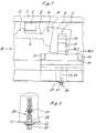
- 1 to 3 with 1 is a with the door frame Shaft door connected support plate, on which a Locking member 2 is attached.
- a locking lever 3 is not rotatable about an axis 4 on one Shown carriage of the landing door shown.
- the Locking lever 3 in the form of a double lever, instructs the one lever arm 5 a hook 6, while on the another lever arm 7 a weight 8 is attached. In locked condition is under the influence of weight 8 the one lever arm 5 raised and the hook 6 with the Locking member 2 in engagement.
- a Bolt 9 attached on the other lever arm 7 of the locking lever 3 .
- a Unlocking slide 10 is arranged, which is slidable on Carrier sheet 1 is guided and held tight.
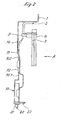
- a cutout 11 is provided in the carrier plate 1 and the carrier plate 1 at the level of the cutout 11 through twisted twice at obtuse angles so deformed that the unlocking slide 10 only on one side of the carrier plate 1 and then performed on the other side becomes.
- a lower part 10.1 of the unlocking slide 10 is wider than an upper part 10.2 of the Unlocking slide 10, being at the upper corners of the lower part 10.1 and the upper part 10.2 friction-reducing pads 12, 13, 14 are provided.
- the Unlocking slide 10 is at its lower end an actuator 20 connected.
- the actuator 20 has a triangular provided actuator 21, which in a Carrier plate 1 mounted bearing plate 22 rotatably mounted is.
- the actuator 21 is with a spindle 23 non-rotatably connected, preferably with a single or multi-course two-course - non-self-locking Steep thread, for example trapezoidal thread, is provided.
- a spindle nut 24 seated on the spindle 23 is also included the unlocking slide 10 screwed so that when Rotating the actuator 21 by means of a Triangular key of the unlocking slide 10 upwards pushed against the bolt 9, the locking lever 3 is pivoted and the shaft door is unlocked.
Landscapes
- Lock And Its Accessories (AREA)
- Elevator Door Apparatuses (AREA)
Abstract
Description
- Fig.1
- Eine Ansicht der Entriegelungsvorrichtung in Richtung A der Fig.2,
- Fig.2
- eine Ansicht der Entriegelungsvorrichtung in Richtung B der Fig.1, in grösserem Massstab und
- Fig.3
- eine Betätigungseinrichtung der Entriegelungsvorrichtung gemäss Fig.1 und 2 in grösserem Massstab.
Claims (8)
- Entriegelungsvorrichtung an Schachttüre von Aufzügen, mit einem Verriegelungshebel (3), welcher mittels eines Entriegelungselements (10) zu entriegeln ist, wobei das Entriegelungselement (10) mit einer Spindel (23) in Wirkverbindung steht, die auf einem Lager (22) drehbar abgestützt ist.
- Entriegelungsvorrichtung nach Anspruch 1,
dadurch gekennzeichnet, dass eine am Entriegelungselement (10) angebrachte Spindelmutter (24) Teil der Wirkverbindung ist - Entriegelungsvorrichtung nach Anspruch 2,
dadurch gekennzeichnet, dass der Verriegelungshebel (3), das Entriegelungselement (10) und die Spindel (23) auf einem Trägerblech (1) montiert sind, wobei das Entriegelungselement (10) als ein am Trägerblech (1) geführter Entriegelungsschieber (10) ausgeführt ist. - Entriegelungsvorrichtung nach Anspruch 1,
dadurch gekennzeichnet, dass die Spindel (23) an einem ihrer Enden ein dreikantförmiges Betätigungsglied (21) aufweist. - Entriegelungsvorrichtung nach Anspruch 3,
dadurch gekennzeichnet, dass im Trägerblech (1) ein Ausschnitt (11) vorgesehen ist, und das Trägerblech (1) auf der Höhe dieses Ausschnittes (11) durch zweimaliges Abbiegen in stumpfen Winkeln derart verformt ist, dass der Ausschnitt (11) eine Durchtrittsöffnung für den Entriegelungsschieber (10) bildet, durch die der Entriegelungsschieber (10) hindurchgeführt ist, wobei dieser erst durch die eine Seite des Trägerbleches (1) und dann durch dessen andere Seite geführt ist. - Entriegelungsvorrichtung nach Anspruch 3,
dadurch gekennzeichnet, dass er reibungsvermindernde Beläge (12,13,14) aufweist. - Entriegelungsvorrichtung nach Anspruch 1,
dadurch gekennzeichnet, dass die Spindel (23) mit einem mehrgängigen, nicht-selbsthemmenden Steilgewinde versehen ist. - Entriegelungsvorrichtung nach Anspruch 5,
dadurch gekennzeichnet, dass das nicht-selbsthemmende Steilgewinde ein Trapezgewinde ist.
Priority Applications (1)
| Application Number | Priority Date | Filing Date | Title |
|---|---|---|---|
| EP20020009915 EP1258444B1 (de) | 2001-05-14 | 2002-05-03 | Entriegelungsvorrichtung an Schachttüren von Aufzügen |
Applications Claiming Priority (3)
| Application Number | Priority Date | Filing Date | Title |
|---|---|---|---|
| EP01810471 | 2001-05-14 | ||
| EP01810471 | 2001-05-14 | ||
| EP20020009915 EP1258444B1 (de) | 2001-05-14 | 2002-05-03 | Entriegelungsvorrichtung an Schachttüren von Aufzügen |
Publications (2)
| Publication Number | Publication Date |
|---|---|
| EP1258444A1 true EP1258444A1 (de) | 2002-11-20 |
| EP1258444B1 EP1258444B1 (de) | 2005-10-05 |
Family
ID=26077374
Family Applications (1)
| Application Number | Title | Priority Date | Filing Date |
|---|---|---|---|
| EP20020009915 Expired - Lifetime EP1258444B1 (de) | 2001-05-14 | 2002-05-03 | Entriegelungsvorrichtung an Schachttüren von Aufzügen |
Country Status (1)
| Country | Link |
|---|---|
| EP (1) | EP1258444B1 (de) |
Citations (4)
| Publication number | Priority date | Publication date | Assignee | Title |
|---|---|---|---|---|
| DE254990C (de) * | ||||
| US1269927A (en) * | 1916-04-08 | 1918-06-18 | Agda E Ziegler | Elevator-door-actuating device. |
| US4454931A (en) * | 1981-09-30 | 1984-06-19 | Otis Elevator Company | Elevator door operator having a variable pitch lead screw |
| FR2670194A1 (fr) * | 1990-12-07 | 1992-06-12 | Otis Elevator Co | Mecanisme de deverrouillage manuel d'une porte d'ascenseur. |
-
2002
- 2002-05-03 EP EP20020009915 patent/EP1258444B1/de not_active Expired - Lifetime
Patent Citations (4)
| Publication number | Priority date | Publication date | Assignee | Title |
|---|---|---|---|---|
| DE254990C (de) * | ||||
| US1269927A (en) * | 1916-04-08 | 1918-06-18 | Agda E Ziegler | Elevator-door-actuating device. |
| US4454931A (en) * | 1981-09-30 | 1984-06-19 | Otis Elevator Company | Elevator door operator having a variable pitch lead screw |
| FR2670194A1 (fr) * | 1990-12-07 | 1992-06-12 | Otis Elevator Co | Mecanisme de deverrouillage manuel d'une porte d'ascenseur. |
Also Published As
| Publication number | Publication date |
|---|---|
| EP1258444B1 (de) | 2005-10-05 |
Similar Documents
| Publication | Publication Date | Title |
|---|---|---|
| EP0513509B1 (de) | Aufzug | |
| EP0332841B1 (de) | Türantriebsvorrichtung mit Verriegelungsmechanismus für Aufzüge | |
| EP1497217B1 (de) | Vorrichtung zur betätigung und verriegelung von aufzugstüren mit mitnehmerkufen | |
| EP0634353B1 (de) | Tür-Zuhalteeinrichtung | |
| DE2753445C2 (de) | ||
| EP1713712B9 (de) | Vorrichtung zur betätigung und verriegelung von aufzugstüren | |
| DE69914269T2 (de) | Vorrichtung zur Öffnung/Schliessung einer Aufzugsschalttafel | |
| DE69300308T2 (de) | Schwenkbetätigungsvorrichtung einer Trittstufenanordnung für Fahrzeuge. | |
| EP1799510A1 (de) | Kraftunterstützungsvorrichtung mit lastabhängiger kraftunterstützung | |
| DE3710237A1 (de) | Fangvorrichtung fuer nach oben oeffnende tore | |
| EP0678639B1 (de) | Verriegelung für Schiebeläden, Schiebetüren und dgl. entlang einer feststehenden Schiene verfahrbare Elemente | |
| DE202010015321U1 (de) | Rolle für Apparate, Geräte, Möbel od. dgl. | |
| EP2706032B1 (de) | Lastaufnahmevorrichtung, insbesondere Unterflasche für ein Hebezeug | |
| DE2419995C3 (de) | Verriegelungsvorrichtung für eine Stockwerkstür eines Fahrstuhlschachtes | |
| DE19907632A1 (de) | Boden für Personenbeförderungsmittel | |
| EP1258444B1 (de) | Entriegelungsvorrichtung an Schachttüren von Aufzügen | |
| DE202006010217U1 (de) | Türverschluss | |
| DE60010658T2 (de) | Sicherheitsbremse für treppenaufzüge | |
| EP0094607A2 (de) | Schrägaufzug für einen Rollstuhl oder dgl. an einem Verkehrsmittel | |
| EP0912811B1 (de) | Schiebetür | |
| DE4221493C2 (de) | Kombinierter Entriegelungs- und Sicherungsmechanismus für eine an der Stirnseite eines Nahverkehrs-Schienenfahrzeuges angeordnete Notausstiegstür | |
| DE69021827T2 (de) | Vorrichtung für die Verriegelung einer Aufzugskabinentür. | |
| EP0744310B1 (de) | Entriegelungs- und Verriegelungseinrichtung für eine Schwenkschiebetür | |
| EP3696043B1 (de) | Nottür für ein schienenfahrzeug | |
| DE102006039570B4 (de) | Nothandkettenentriegelung |
Legal Events
| Date | Code | Title | Description |
|---|---|---|---|
| PUAI | Public reference made under article 153(3) epc to a published international application that has entered the european phase |
Free format text: ORIGINAL CODE: 0009012 |
|
| AK | Designated contracting states |
Kind code of ref document: A1 Designated state(s): AT BE CH CY DE DK ES FI FR GB GR IE IT LI LU MC NL PT SE TR |
|
| AX | Request for extension of the european patent |
Free format text: AL;LT;LV;MK;RO;SI |
|
| 17P | Request for examination filed |
Effective date: 20030428 |
|
| AKX | Designation fees paid |
Designated state(s): AT CH DE FR GB LI |
|
| 17Q | First examination report despatched |
Effective date: 20040402 |
|
| GRAP | Despatch of communication of intention to grant a patent |
Free format text: ORIGINAL CODE: EPIDOSNIGR1 |
|
| GRAS | Grant fee paid |
Free format text: ORIGINAL CODE: EPIDOSNIGR3 |
|
| GRAA | (expected) grant |
Free format text: ORIGINAL CODE: 0009210 |
|
| AK | Designated contracting states |
Kind code of ref document: B1 Designated state(s): AT CH DE FR GB LI |
|
| REG | Reference to a national code |
Ref country code: GB Ref legal event code: FG4D Free format text: NOT ENGLISH |
|
| REG | Reference to a national code |
Ref country code: CH Ref legal event code: EP |
|
| REF | Corresponds to: |
Ref document number: 50204433 Country of ref document: DE Date of ref document: 20051110 Kind code of ref document: P |
|
| GBT | Gb: translation of ep patent filed (gb section 77(6)(a)/1977) |
Effective date: 20051111 |
|
| ET | Fr: translation filed | ||
| PLBE | No opposition filed within time limit |
Free format text: ORIGINAL CODE: 0009261 |
|
| STAA | Information on the status of an ep patent application or granted ep patent |
Free format text: STATUS: NO OPPOSITION FILED WITHIN TIME LIMIT |
|
| 26N | No opposition filed |
Effective date: 20060706 |
|
| PGFP | Annual fee paid to national office [announced via postgrant information from national office to epo] |
Ref country code: FR Payment date: 20110607 Year of fee payment: 10 |
|
| PGFP | Annual fee paid to national office [announced via postgrant information from national office to epo] |
Ref country code: GB Payment date: 20110520 Year of fee payment: 10 Ref country code: AT Payment date: 20110512 Year of fee payment: 10 |
|
| PGFP | Annual fee paid to national office [announced via postgrant information from national office to epo] |
Ref country code: DE Payment date: 20110520 Year of fee payment: 10 |
|
| PGFP | Annual fee paid to national office [announced via postgrant information from national office to epo] |
Ref country code: CH Payment date: 20110812 Year of fee payment: 10 |
|
| REG | Reference to a national code |
Ref country code: CH Ref legal event code: PL |
|
| REG | Reference to a national code |
Ref country code: AT Ref legal event code: MM01 Ref document number: 305897 Country of ref document: AT Kind code of ref document: T Effective date: 20120503 |
|
| GBPC | Gb: european patent ceased through non-payment of renewal fee |
Effective date: 20120503 |
|
| PG25 | Lapsed in a contracting state [announced via postgrant information from national office to epo] |
Ref country code: LI Free format text: LAPSE BECAUSE OF NON-PAYMENT OF DUE FEES Effective date: 20120531 Ref country code: CH Free format text: LAPSE BECAUSE OF NON-PAYMENT OF DUE FEES Effective date: 20120531 Ref country code: AT Free format text: LAPSE BECAUSE OF NON-PAYMENT OF DUE FEES Effective date: 20120503 |
|
| REG | Reference to a national code |
Ref country code: FR Ref legal event code: ST Effective date: 20130131 |
|
| REG | Reference to a national code |
Ref country code: DE Ref legal event code: R119 Ref document number: 50204433 Country of ref document: DE Effective date: 20121201 |
|
| PG25 | Lapsed in a contracting state [announced via postgrant information from national office to epo] |
Ref country code: GB Free format text: LAPSE BECAUSE OF NON-PAYMENT OF DUE FEES Effective date: 20120503 Ref country code: FR Free format text: LAPSE BECAUSE OF NON-PAYMENT OF DUE FEES Effective date: 20120531 |
|
| PG25 | Lapsed in a contracting state [announced via postgrant information from national office to epo] |
Ref country code: DE Free format text: LAPSE BECAUSE OF NON-PAYMENT OF DUE FEES Effective date: 20121201 |