EP1258411B1 - Induktiver Schienenkontakt - Google Patents
Induktiver Schienenkontakt Download PDFInfo
- Publication number
- EP1258411B1 EP1258411B1 EP02360132A EP02360132A EP1258411B1 EP 1258411 B1 EP1258411 B1 EP 1258411B1 EP 02360132 A EP02360132 A EP 02360132A EP 02360132 A EP02360132 A EP 02360132A EP 1258411 B1 EP1258411 B1 EP 1258411B1
- Authority
- EP
- European Patent Office
- Prior art keywords
- filter circuit
- input
- comparator
- limiter
- preliminary filter
- Prior art date
- Legal status (The legal status is an assumption and is not a legal conclusion. Google has not performed a legal analysis and makes no representation as to the accuracy of the status listed.)
- Expired - Lifetime
Links
- 230000001939 inductive effect Effects 0.000 title claims description 8
- 230000001629 suppression Effects 0.000 claims description 2
- 238000011045 prefiltration Methods 0.000 description 6
- 230000002238 attenuated effect Effects 0.000 description 1
- 238000001514 detection method Methods 0.000 description 1
- 230000000694 effects Effects 0.000 description 1
- 230000036039 immunity Effects 0.000 description 1
- 230000011664 signaling Effects 0.000 description 1
Images
Classifications
-
- B—PERFORMING OPERATIONS; TRANSPORTING
- B61—RAILWAYS
- B61L—GUIDING RAILWAY TRAFFIC; ENSURING THE SAFETY OF RAILWAY TRAFFIC
- B61L1/00—Devices along the route controlled by interaction with the vehicle or train
- B61L1/16—Devices for counting axles; Devices for counting vehicles
- B61L1/163—Detection devices
- B61L1/165—Electrical
-
- B—PERFORMING OPERATIONS; TRANSPORTING
- B61—RAILWAYS
- B61L—GUIDING RAILWAY TRAFFIC; ENSURING THE SAFETY OF RAILWAY TRAFFIC
- B61L1/00—Devices along the route controlled by interaction with the vehicle or train
- B61L1/16—Devices for counting axles; Devices for counting vehicles
- B61L1/167—Circuit details
Definitions
- the invention relates to an inductive rail contact.
- Inductive rail contacts are used in particular in railway signaling in Achsbeatenem. They are used to detect axles of a passing train. Axle counters are used for track vacancy.
- the linear eddy current brake which is to be used in the ICE3 can be used to couple strong electromagnetic interference pulses to the rail contact receiver head, which facilitates the detection of the useful signals, i. of the axes, can negatively influence.
- the narrow, pulsed disturbances excite the receiving resonant circuit of the rail contact and it oscillates to resonant frequency with sinusoidal voltage. Since the resonance frequency is equal to the useful frequency and the amplitude is considerably higher than that of the useful signal, the useful signal can no longer be evaluated.
- the DE 196 41 392 A1 describes a sensor, in particular for use in wheel sensors in railway operation, wherein in the feedback circuit of an oscillator transistor, a filter with high-pass behavior is connected. As a result, low-frequency interference voltages are attenuated, while the higher-frequency sensor voltage can pass unattenuated.
- the object of the invention is to provide a rail contact, the immunity to interference, especially from a linear eddy current brake is increased.
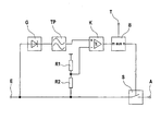
- the figure shows a prefilter circuit according to the invention of an inductive rail contact.
- the pre-filter circuit has an input E and an output A. Output A is connected to the receiving head of the rail contact.
- Input E is connected to output A via a switch S.
- the pre-filter circuit includes a rectifier G, a low-pass filter TP, a comparator K, a limiter B, and two ohmic resistors R1, R2.
- the input of the rectifier G is connected to input E.
- the output of the rectifier G is connected to the input of the low-pass filter TP.
- the output of the low-pass filter TP is connected to the positive input of the comparator K.
- the output of the comparator K is connected to the input of the limiter B.
- the output of the limiter B is connected to the control input of the switch S.
- Limiter B has a clock input T, via which the limiter B, a clock signal is supplied.
- Resistor R1 and resistor R2 are connected in series and form a voltage divider.
- the one terminal of resistor R1 is connected to a positive reference voltage, the other terminal to the negative input of comparator K and the one terminal of resistor R2.
- the other port of R2 is connected to input E.
- the AC input signal at the input E is rectified in the rectifier G, integrated in the low-pass filter TP and then fed to the comparator K.
- the AC input signal at input E is also supplied via resistor R2 with reduced amplitude comparator K.
- the switch S opens for the duration of the fault, but at most for the duration defined by limiter B.
- the permissible ratio of maximum disturbance duration is set to undisturbed duration and thus the maximum duration of an open switch position; m and n are each natural numbers greater than or equal to one.
- the pre-filter circuit described so far is used to suppress interference during the positive half cycles of the AC input signal at input E.
- the pre-filter circuit can be extended as follows:
- the pre-filter circuit is added with an additional rectifier, an additional low-pass filter, an additional comparator, two additional ohmic resistors.
- the output of the additional rectifier is connected to input E, the input of the additional rectifier to the input of the additional low-pass filter.
- the output of the additional low-pass filter is connected to the negative input of the additional comparator.
- the output of the additional comparator is connected to an additional input on the limiter B.
- the additional resistors are connected in series and form a voltage divider.
- One terminal of one resistor is connected to a negative reference voltage, the other terminal to the positive input of comparator K and one terminal of another resistor.
- the other terminal of the other resistor is connected to input E.
- Limiter B combines the outputs of both comparators with an OR operation and controls switch S for both positive and negative half-wave interference.
Landscapes
- Engineering & Computer Science (AREA)
- Automation & Control Theory (AREA)
- Mechanical Engineering (AREA)
- Train Traffic Observation, Control, And Security (AREA)
- Electric Propulsion And Braking For Vehicles (AREA)
- Electrophonic Musical Instruments (AREA)
- Measurement Of Current Or Voltage (AREA)
- Emergency Protection Circuit Devices (AREA)
Description
- Die Erfindung betrifft einen induktiven Schienenkontakt.
- Induktive Schienenkontakte werden insbesondere in der Eisenbahnsignaltechnik in Achszählem eingesetzt. Sie dienen der Detektion von Achsen eines vorüberfahrenden Zuges. Achszähler werden zur Gleisfreimeldung eingesetzt.
- Über die lineare Wirbelstrombremse, die beim ICE3 zur Anwendung kommen soll, können starke, elektromagnetische Störimpulse auf den Empfangskopf des Schienenkontaktes eingekoppelt werden, die die Detektion der Nutzsignale, d.h. der Achsen, negativ beeinflussen können.
- Die schmalen, impulsförmigen Störungen regen den Empfangsschwingkreis des Schienenkontaktes an und er schwingt auf Resonanzfrequenz mit sinusförmiger Spannung aus. Da die Resonanzfrequenz gleich der Nutzfrequenz ist und die Amplitude erheblich über der des Nutzsignals liegt, ist das Nutzsignal nicht mehr auswertbar.
- Die
DE 196 41 392 A1 beschreibt einen Sensor, insbesondere für die Anwendung bei Radsensoren im Bahnbetrieb, wobei im Rückkopplungskreis eines Oszillatortransistors ein Filter mit Hochpassverhalten geschaltet ist. Dadurch werden niederfrequente Störspannungen bedämpft, während die höherfrequente Sensorspannung ungedämpft passieren kann. - Aufgabe der Erfindung ist es, einen Schienenkontakt zu schaffen, dessen Störfestigkeit gegen Störimpulse, insbesondere von einer linearen Wirbelstrombremse, erhöht ist.
- Gelöst wird diese Aufgabe durch einen Schienenkontakt gemäß Patentanspruch 1.
- Durch Unterbrechen des Signalweges während der kurzzeitigen Störeinwirkung und dem Festhalten des Signals auf dem ungestörten Wert für eine begrenzte Dauer, kann ein ausreichender Störabstand erzielt werden.
- Im folgenden wird ein Ausführungsbeispiel der Erfindung anhand einer Figur erläutert.
- Die Figur zeigt eine erfindungsgemäße Vorfilterschaltung eines induktiven Schienenkontaktes.
- Die Vorfilterschaltung hat einen Eingang E und einen Ausgang A. Ausgang A ist mit dem Empfangskopf des Schienenkontaktes verbunden.
- Eingang E ist mit Ausgang A über einen Schalter S verbunden.
- Die Vorfilterschaltung beinhaltet einen Gleichrichter G, ein Tiefpassfilter TP, einen Komparator K, einen Begrenzer B, sowie zwei ohmsche Widerstände R1, R2.
- Der Eingang des Gleichrichters G ist mit Eingang E verbunden. Der Ausgang des Gleichrichters G ist mit dem Eingang des Tiefpassfilters TP verbunden. Der Ausgang des Tiefpassfilters TP ist mit dem positiven Eingang des Komparators K verbunden. Der Ausgang des Komparators K ist mit dem Eingang des Begrenzers B verbunden. Der Ausgang des Begrenzers B ist mit dem Steuereingang des Schalters S verbunden.
- Begrenzer B weist einen Takteingang T auf, über den dem Begrenzer B ein Taktsignal zugeführt wird.
- Widerstand R1 und Widerstand R2 sind in Reihe geschaltet und bilden ein Spannungsteiler. Der eine Anschluss des Widerstands R1 ist mit einer positiven Referenzspannung verbunden, der andere Anschluss mit dem negativen Eingang von Komparator K und dem einen Anschluss von Widerstand R2. Der andere Anschluss von R2 ist mit Eingang E verbunden.
- Das Wechselspannungseingangssignal am Eingang E wird im Gleichrichter G gleichgerichtet, Im Tiefpassfilter TP integriert und anschließend dem Komparator K zugeführt.
- Das Wechselspannungseingangssignal am Eingang E wird zudem über Widerstand R2 mit reduzierter Amplitude Komparator K zugeführt.
- Überschreitet das Eingangssignal am negativen Eingang des Komparators K das Eingangssignal am positiven Eingang des Komparators K, z.B. auf Grund einer überlagerten Störung, so öffnet der Schalter S für die Dauer der Störung, maximal jedoch für die durch Begrenzer B festgelegten Dauer.
- Durch Wahl der Widerstandswerte von R1 und R2 wird die Amplitude für das Wirksamwerden der Störungsunterdrückung festgelegt.
- Durch die Wahl von m und n Takten im Begrenzer B wird das zulässige Verhältnis von maximaler Störungsdauer zu ungestörter Dauer festgelegt und damit die maximale Dauer einer geöffneten Schalterstellung; m und n sind jeweils natürliche Zahlen größer gleich Eins.
- Auf Grund der relativ langsamen Empfangskopfschaltung wird das Nutzsignal für die Dauer der Störeinwirkung und damit für die Dauer des geöffneten Schalters S festgehalten. Dies bedeutet, dass am Ausgang A bei Öffnen des Schalters S weiterhin der Wert anliegt, der vor dem Öffnen anlag und nicht ein undefinierter Wert, d.h. Ausgang A floated nicht für die Dauer der Öffnung des Schalters S.
- Die bisher beschriebene Vorfilterschaltung dient zur Unterdrückung von Störungen während der positiven Halbwellen des Wechselspannungseingangssignal am Eingang E. Zur Unterdrückung von Störungen während der negativen Halbwellen des Wechselspannungseingangssignal am Eingang E kann die Vorfilterschaltung wie folgt erweitert werden:
- Der Vorfilterschaltung werden hinzugefügt ein zusätzlicher Gleichrichter, ein zusätzliches Tiefpassfilter, ein zusätzlicher Komparator, zwei zusätzliche ohmsche Widerstände.
- Der Ausgang des zusätzlichen Gleichrichters wird mit Eingang E verbunden, der Eingang des zusätzlichen Gleichrichters mit dem Eingang des zusätzlichen Tiefpassfilters. Der Ausgang des zusätzlichen Tiefpassfilters wird mit dem negativen Eingang des zusätzlichen Komparators verbunden. Der Ausgang des zusätzlichen Komparators wird mit einem zusätzlichen Eingang am Begrenzer B verbunden.
- Die zusätzlichen Widerstände sind in Reihe geschaltet und bilden ein Spannungsteiler. Der eine Anschluss des einen Widerstands ist mit einer negativen Referenzspannung verbunden, der andere Anschluss mit dem positiven Eingang von Komparator K und dem einen Anschluss von anderen Widerstand. Der andere Anschluss des anderen Widerstands ist mit Eingang E verbunden.
- Auf gleiche Art und Weise werden somit Störungen bei negativen Halbwellen unterdrückt wie bei positiven Halbwellen. Begrenzer B verknüpft die Ausgänge beider Komparatoren dazu mit einer ODER-Verknüpfung und steuert Schalter S sowohl für positive als auch für negative Halbwellenstörungen.
Claims (4)
- Induktiver Schienenkontakt, umfassend eine Vorfilterschaitung zur Störungsunterdrückung,
dadurch gekennzeichnet,
dass die Vorfilterschaltung dazu geeignet ist, bei Auftreten einer Störung im Wechselspannungseingangssignal ein Weiterleiten des Wechselspannungseingangssignals zu unterdrücken,
wobei zwischen einem Eingang (E) und einem Ausgang (A) der Vorfilterschaltung ein Schalter (S) vorgesehen ist,
und wobei die Vorfilterschaltung dazu ausgebildet ist, bei Auftreten einer Störung im Wechselspannungseingangssignal den Schalter (S) zu öffnen. - Induktiver Schienenkontakt gemäf3 Anspruch 1, dadurch gekennzeichnet, dass die Vorfilterschaltung eine Reihenschaltung aus einem Gleichrichter (G), einem Tiefpassfilter (TP), einem Komparator (K) und einem Begrenzer (B) beinhaltet sowie einen Spannungsteiler (R1, R2), über den das Wechselspannungseingangssignal dem negativen Eingang des Komparators mit reduzierter Amplitude zuführbar ist, und dass der Schalter (S), der zwischen Eingang (E) und Ausgang (A) der Vorfilterschaltung geschaltet ist, über den Begrenzer (B) angesteuert wird.
- Induktiver Schienenkontakt gemäß Anspruch 2, dadurch gekennzeichnet, dass der Begrenzer (B) geeignet ist, die Dauer der Öffnung des Schalters (S) für jedes Auftreten einer Störung auf eine maximale, durch den Begrenzer (B) festgelegte Dauer zu begrenzen.
- Induktiver Schienenkontakt gemäß Anspruch 2, dadurch gekennzeichnet, dass die Vofilterschaltung eine Reihenschaltung aus einem weiteren Gleichrichter, einem weiteren Tiefpassfilter, einem weiteren Komparator beinhaltet sowie einen weiteren Spannungsteiler, über den das Wechselspannungseingangssignal dem positiven Eingang des weiteren Komparators mit im Betrag reduzierter Amplitude zuführbar ist, und dass der weitere Gleichrichter mit dem Eingang der Vorfitterschaltung verbunden ist und der Ausgang des weiteren Komparators mit dem Begrenzer (B).
Applications Claiming Priority (2)
| Application Number | Priority Date | Filing Date | Title |
|---|---|---|---|
| DE10123673A DE10123673A1 (de) | 2001-05-16 | 2001-05-16 | Induktiver Schienenkontakt |
| DE10123673 | 2001-05-16 |
Publications (2)
| Publication Number | Publication Date |
|---|---|
| EP1258411A1 EP1258411A1 (de) | 2002-11-20 |
| EP1258411B1 true EP1258411B1 (de) | 2009-09-02 |
Family
ID=7684903
Family Applications (1)
| Application Number | Title | Priority Date | Filing Date |
|---|---|---|---|
| EP02360132A Expired - Lifetime EP1258411B1 (de) | 2001-05-16 | 2002-04-29 | Induktiver Schienenkontakt |
Country Status (3)
| Country | Link |
|---|---|
| EP (1) | EP1258411B1 (de) |
| AT (1) | ATE441564T1 (de) |
| DE (2) | DE10123673A1 (de) |
Families Citing this family (1)
| Publication number | Priority date | Publication date | Assignee | Title |
|---|---|---|---|---|
| DE102007023475B4 (de) * | 2007-05-15 | 2009-07-09 | Siemens Ag | Radsensor |
Family Cites Families (3)
| Publication number | Priority date | Publication date | Assignee | Title |
|---|---|---|---|---|
| DD135023A1 (de) * | 1978-03-17 | 1979-04-04 | Seifert Hans Peter | Schaltungsanordnung zur automatischen austastung von stoerungen beim am-empfang |
| DE3235674C2 (de) * | 1982-09-27 | 1984-10-31 | Siemens AG, 1000 Berlin und 8000 München | Schaltungsanordnung zum Erzeugen von Achszählimpulsen für Achszählanlagen |
| DE19641392B4 (de) | 1996-09-27 | 2008-07-31 | Siemens Ag | Sensor |
-
2001
- 2001-05-16 DE DE10123673A patent/DE10123673A1/de not_active Withdrawn
-
2002
- 2002-04-29 AT AT02360132T patent/ATE441564T1/de not_active IP Right Cessation
- 2002-04-29 EP EP02360132A patent/EP1258411B1/de not_active Expired - Lifetime
- 2002-04-29 DE DE50213807T patent/DE50213807D1/de not_active Expired - Lifetime
Also Published As
| Publication number | Publication date |
|---|---|
| ATE441564T1 (de) | 2009-09-15 |
| DE10123673A1 (de) | 2002-11-21 |
| DE50213807D1 (de) | 2009-10-15 |
| EP1258411A1 (de) | 2002-11-20 |
Similar Documents
| Publication | Publication Date | Title |
|---|---|---|
| DE3505052A1 (de) | Durchtrittssicherheitssystem | |
| DE102016113159A1 (de) | Von Störungen unbeeinflusste Stromerfassungsschaltung | |
| DE19641392B4 (de) | Sensor | |
| EP0525345B2 (de) | Vorrichtung und Verfahren zum Überwachen einer Flamme | |
| DE602005003117T2 (de) | System und verfahren zum prüfen mechanischer stücke mit drahtloser signalübertragung | |
| DE10010370A1 (de) | Auswerteschaltung für einen magnetoresistiven Sensor | |
| EP1258411A1 (de) | Induktiver Schienenkontakt | |
| WO1998008058A1 (de) | Schaltungsanordnung zur eigensicheren erfassung von binären signalen eines gebers | |
| DE4429314A1 (de) | Induktiver Näherungsschalter | |
| EP1214787B1 (de) | Verfahren zur detektion und auswertung kleiner kapazitätsänderungen zur umsetzung in ein schaltsignal und kapazitiver sensor hierzu | |
| CH674343A5 (de) | ||
| DE1078170B (de) | Zwei stabile Remanenzzustaende aufweisender ringfoermiger Magnetkern | |
| DE10137091A1 (de) | Induktiver Näherungssensor | |
| DE10216784A1 (de) | Netzteil | |
| AT412634B (de) | Fahrzeuggerät für die punktförmige induktive zugbeeinflussung | |
| EP0697769A1 (de) | Magnetischer Näherungsdetektor | |
| DE19828058B4 (de) | Schaltung zur Erkennung einer Leitungsunterbrechung für ein digitales Signal | |
| EP1187330A2 (de) | Spannungskomparatorschaltung für die Einhüllende einer Wechselspannung und Verfahren dazu | |
| DE3342710C1 (de) | Näherungsschalter mit Überwachung der Funktion und Funktionsbereitschaft | |
| DE3402349C2 (de) | ||
| DE102008033090A1 (de) | Induktiver Sensor | |
| DE3109849C2 (de) | Schaltungsanordnung zur Identifikation von empfangenen Sendern mit gleichem Modulationsinhalt | |
| DE1008357B (de) | Magnetverstaerker | |
| DE2431433C3 (de) | Spitzenspannungsdetektor | |
| EP0458044A2 (de) | Auswerteschaltung für die Signale einer Signalquelle |
Legal Events
| Date | Code | Title | Description |
|---|---|---|---|
| PUAI | Public reference made under article 153(3) epc to a published international application that has entered the european phase |
Free format text: ORIGINAL CODE: 0009012 |
|
| 17P | Request for examination filed |
Effective date: 20020903 |
|
| AK | Designated contracting states |
Kind code of ref document: A1 Designated state(s): AT BE CH CY DE DK ES FI FR GB GR IE IT LI LU MC NL PT SE TR |
|
| AX | Request for extension of the european patent |
Free format text: AL;LT;LV;MK;RO;SI |
|
| AKX | Designation fees paid |
Designated state(s): AT BE CH CY DE DK ES FI FR GB GR IE IT LI LU MC NL PT SE TR |
|
| RAP1 | Party data changed (applicant data changed or rights of an application transferred) |
Owner name: ALCATEL LUCENT |
|
| 17Q | First examination report despatched |
Effective date: 20080902 |
|
| GRAP | Despatch of communication of intention to grant a patent |
Free format text: ORIGINAL CODE: EPIDOSNIGR1 |
|
| GRAS | Grant fee paid |
Free format text: ORIGINAL CODE: EPIDOSNIGR3 |
|
| GRAA | (expected) grant |
Free format text: ORIGINAL CODE: 0009210 |
|
| AK | Designated contracting states |
Kind code of ref document: B1 Designated state(s): AT BE CH CY DE DK ES FI FR GB GR IE IT LI LU MC NL PT SE TR |
|
| REG | Reference to a national code |
Ref country code: CH Ref legal event code: EP |
|
| REG | Reference to a national code |
Ref country code: IE Ref legal event code: FG4D Free format text: LANGUAGE OF EP DOCUMENT: GERMAN |
|
| REF | Corresponds to: |
Ref document number: 50213807 Country of ref document: DE Date of ref document: 20091015 Kind code of ref document: P |
|
| PG25 | Lapsed in a contracting state [announced via postgrant information from national office to epo] |
Ref country code: SE Free format text: LAPSE BECAUSE OF FAILURE TO SUBMIT A TRANSLATION OF THE DESCRIPTION OR TO PAY THE FEE WITHIN THE PRESCRIBED TIME-LIMIT Effective date: 20090902 Ref country code: FI Free format text: LAPSE BECAUSE OF FAILURE TO SUBMIT A TRANSLATION OF THE DESCRIPTION OR TO PAY THE FEE WITHIN THE PRESCRIBED TIME-LIMIT Effective date: 20090902 |
|
| NLV1 | Nl: lapsed or annulled due to failure to fulfill the requirements of art. 29p and 29m of the patents act | ||
| PG25 | Lapsed in a contracting state [announced via postgrant information from national office to epo] |
Ref country code: NL Free format text: LAPSE BECAUSE OF FAILURE TO SUBMIT A TRANSLATION OF THE DESCRIPTION OR TO PAY THE FEE WITHIN THE PRESCRIBED TIME-LIMIT Effective date: 20090902 |
|
| PG25 | Lapsed in a contracting state [announced via postgrant information from national office to epo] |
Ref country code: CY Free format text: LAPSE BECAUSE OF FAILURE TO SUBMIT A TRANSLATION OF THE DESCRIPTION OR TO PAY THE FEE WITHIN THE PRESCRIBED TIME-LIMIT Effective date: 20090902 |
|
| REG | Reference to a national code |
Ref country code: IE Ref legal event code: FD4D |
|
| PG25 | Lapsed in a contracting state [announced via postgrant information from national office to epo] |
Ref country code: ES Free format text: LAPSE BECAUSE OF FAILURE TO SUBMIT A TRANSLATION OF THE DESCRIPTION OR TO PAY THE FEE WITHIN THE PRESCRIBED TIME-LIMIT Effective date: 20091213 Ref country code: IE Free format text: LAPSE BECAUSE OF FAILURE TO SUBMIT A TRANSLATION OF THE DESCRIPTION OR TO PAY THE FEE WITHIN THE PRESCRIBED TIME-LIMIT Effective date: 20090902 Ref country code: PT Free format text: LAPSE BECAUSE OF FAILURE TO SUBMIT A TRANSLATION OF THE DESCRIPTION OR TO PAY THE FEE WITHIN THE PRESCRIBED TIME-LIMIT Effective date: 20100104 |
|
| PLBE | No opposition filed within time limit |
Free format text: ORIGINAL CODE: 0009261 |
|
| STAA | Information on the status of an ep patent application or granted ep patent |
Free format text: STATUS: NO OPPOSITION FILED WITHIN TIME LIMIT |
|
| PG25 | Lapsed in a contracting state [announced via postgrant information from national office to epo] |
Ref country code: DK Free format text: LAPSE BECAUSE OF FAILURE TO SUBMIT A TRANSLATION OF THE DESCRIPTION OR TO PAY THE FEE WITHIN THE PRESCRIBED TIME-LIMIT Effective date: 20090902 |
|
| 26N | No opposition filed |
Effective date: 20100603 |
|
| PG25 | Lapsed in a contracting state [announced via postgrant information from national office to epo] |
Ref country code: GR Free format text: LAPSE BECAUSE OF FAILURE TO SUBMIT A TRANSLATION OF THE DESCRIPTION OR TO PAY THE FEE WITHIN THE PRESCRIBED TIME-LIMIT Effective date: 20091203 |
|
| BERE | Be: lapsed |
Owner name: ALCATEL LUCENT Effective date: 20100430 |
|
| PG25 | Lapsed in a contracting state [announced via postgrant information from national office to epo] |
Ref country code: MC Free format text: LAPSE BECAUSE OF NON-PAYMENT OF DUE FEES Effective date: 20100430 |
|
| REG | Reference to a national code |
Ref country code: CH Ref legal event code: PL |
|
| PG25 | Lapsed in a contracting state [announced via postgrant information from national office to epo] |
Ref country code: CH Free format text: LAPSE BECAUSE OF NON-PAYMENT OF DUE FEES Effective date: 20100430 Ref country code: LI Free format text: LAPSE BECAUSE OF NON-PAYMENT OF DUE FEES Effective date: 20100430 |
|
| PG25 | Lapsed in a contracting state [announced via postgrant information from national office to epo] |
Ref country code: BE Free format text: LAPSE BECAUSE OF NON-PAYMENT OF DUE FEES Effective date: 20100430 |
|
| PG25 | Lapsed in a contracting state [announced via postgrant information from national office to epo] |
Ref country code: AT Free format text: LAPSE BECAUSE OF NON-PAYMENT OF DUE FEES Effective date: 20100429 |
|
| PG25 | Lapsed in a contracting state [announced via postgrant information from national office to epo] |
Ref country code: LU Free format text: LAPSE BECAUSE OF NON-PAYMENT OF DUE FEES Effective date: 20100429 |
|
| PG25 | Lapsed in a contracting state [announced via postgrant information from national office to epo] |
Ref country code: TR Free format text: LAPSE BECAUSE OF FAILURE TO SUBMIT A TRANSLATION OF THE DESCRIPTION OR TO PAY THE FEE WITHIN THE PRESCRIBED TIME-LIMIT Effective date: 20090902 |
|
| REG | Reference to a national code |
Ref country code: FR Ref legal event code: PLFP Year of fee payment: 14 |
|
| REG | Reference to a national code |
Ref country code: FR Ref legal event code: CA Effective date: 20150521 |
|
| REG | Reference to a national code |
Ref country code: FR Ref legal event code: CA Effective date: 20150521 |
|
| PGFP | Annual fee paid to national office [announced via postgrant information from national office to epo] |
Ref country code: GB Payment date: 20150429 Year of fee payment: 14 Ref country code: DE Payment date: 20150422 Year of fee payment: 14 |
|
| PGFP | Annual fee paid to national office [announced via postgrant information from national office to epo] |
Ref country code: FR Payment date: 20150408 Year of fee payment: 14 Ref country code: IT Payment date: 20150415 Year of fee payment: 14 |
|
| REG | Reference to a national code |
Ref country code: DE Ref legal event code: R119 Ref document number: 50213807 Country of ref document: DE |
|
| GBPC | Gb: european patent ceased through non-payment of renewal fee |
Effective date: 20160429 |
|
| REG | Reference to a national code |
Ref country code: FR Ref legal event code: ST Effective date: 20161230 |
|
| PG25 | Lapsed in a contracting state [announced via postgrant information from national office to epo] |
Ref country code: FR Free format text: LAPSE BECAUSE OF NON-PAYMENT OF DUE FEES Effective date: 20160502 Ref country code: GB Free format text: LAPSE BECAUSE OF NON-PAYMENT OF DUE FEES Effective date: 20160429 Ref country code: DE Free format text: LAPSE BECAUSE OF NON-PAYMENT OF DUE FEES Effective date: 20161101 |
|
| PG25 | Lapsed in a contracting state [announced via postgrant information from national office to epo] |
Ref country code: IT Free format text: LAPSE BECAUSE OF NON-PAYMENT OF DUE FEES Effective date: 20160429 |