EP1256687A1 - Punkthalter - Google Patents
Punkthalter Download PDFInfo
- Publication number
- EP1256687A1 EP1256687A1 EP02008907A EP02008907A EP1256687A1 EP 1256687 A1 EP1256687 A1 EP 1256687A1 EP 02008907 A EP02008907 A EP 02008907A EP 02008907 A EP02008907 A EP 02008907A EP 1256687 A1 EP1256687 A1 EP 1256687A1
- Authority
- EP
- European Patent Office
- Prior art keywords
- point holder
- plate
- clamping part
- point
- holder according
- Prior art date
- Legal status (The legal status is an assumption and is not a legal conclusion. Google has not performed a legal analysis and makes no representation as to the accuracy of the status listed.)
- Granted
Links
- 239000005336 safety glass Substances 0.000 claims abstract description 12
- 229920003023 plastic Polymers 0.000 claims abstract description 6
- 239000004033 plastic Substances 0.000 claims abstract description 6
- 239000004020 conductor Substances 0.000 claims description 51
- 239000011521 glass Substances 0.000 claims description 32
- 125000006850 spacer group Chemical group 0.000 claims description 10
- 229920001971 elastomer Polymers 0.000 claims description 3
- 238000002347 injection Methods 0.000 claims 1
- 239000007924 injection Substances 0.000 claims 1
- 239000000463 material Substances 0.000 abstract description 5
- 239000005357 flat glass Substances 0.000 abstract 1
- 238000004382 potting Methods 0.000 abstract 1
- 239000000725 suspension Substances 0.000 description 5
- 238000010276 construction Methods 0.000 description 2
- 239000000806 elastomer Substances 0.000 description 2
- 230000003287 optical effect Effects 0.000 description 2
- 239000011347 resin Substances 0.000 description 2
- 229920005989 resin Polymers 0.000 description 2
- 229930040373 Paraformaldehyde Natural products 0.000 description 1
- 238000009435 building construction Methods 0.000 description 1
- 230000000295 complement effect Effects 0.000 description 1
- 239000000428 dust Substances 0.000 description 1
- 238000005286 illumination Methods 0.000 description 1
- 238000012423 maintenance Methods 0.000 description 1
- 239000002184 metal Substances 0.000 description 1
- 229910044991 metal oxide Inorganic materials 0.000 description 1
- 150000004706 metal oxides Chemical class 0.000 description 1
- 230000000149 penetrating effect Effects 0.000 description 1
- -1 polyoxymethylene Polymers 0.000 description 1
- 229920006324 polyoxymethylene Polymers 0.000 description 1
- 230000001681 protective effect Effects 0.000 description 1
- 238000006748 scratching Methods 0.000 description 1
- 230000002393 scratching effect Effects 0.000 description 1
- 238000007789 sealing Methods 0.000 description 1
- 238000000926 separation method Methods 0.000 description 1
Images



Classifications
-
- E—FIXED CONSTRUCTIONS
- E06—DOORS, WINDOWS, SHUTTERS, OR ROLLER BLINDS IN GENERAL; LADDERS
- E06B—FIXED OR MOVABLE CLOSURES FOR OPENINGS IN BUILDINGS, VEHICLES, FENCES OR LIKE ENCLOSURES IN GENERAL, e.g. DOORS, WINDOWS, BLINDS, GATES
- E06B3/00—Window sashes, door leaves, or like elements for closing wall or like openings; Layout of fixed or moving closures, e.g. windows in wall or like openings; Features of rigidly-mounted outer frames relating to the mounting of wing frames
- E06B3/54—Fixing of glass panes or like plates
- E06B3/5436—Fixing of glass panes or like plates involving holes or indentations in the pane
- E06B3/5445—Support arms engaging the holes or indentations
-
- E—FIXED CONSTRUCTIONS
- E04—BUILDING
- E04B—GENERAL BUILDING CONSTRUCTIONS; WALLS, e.g. PARTITIONS; ROOFS; FLOORS; CEILINGS; INSULATION OR OTHER PROTECTION OF BUILDINGS
- E04B7/00—Roofs; Roof construction with regard to insulation
-
- E—FIXED CONSTRUCTIONS
- E04—BUILDING
- E04F—FINISHING WORK ON BUILDINGS, e.g. STAIRS, FLOORS
- E04F11/00—Stairways, ramps, or like structures; Balustrades; Handrails
- E04F11/18—Balustrades; Handrails
- E04F11/181—Balustrades
- E04F11/1851—Filling panels, e.g. concrete, sheet metal panels
- E04F11/1853—Glass panels
-
- E—FIXED CONSTRUCTIONS
- E06—DOORS, WINDOWS, SHUTTERS, OR ROLLER BLINDS IN GENERAL; LADDERS
- E06B—FIXED OR MOVABLE CLOSURES FOR OPENINGS IN BUILDINGS, VEHICLES, FENCES OR LIKE ENCLOSURES IN GENERAL, e.g. DOORS, WINDOWS, BLINDS, GATES
- E06B3/00—Window sashes, door leaves, or like elements for closing wall or like openings; Layout of fixed or moving closures, e.g. windows in wall or like openings; Features of rigidly-mounted outer frames relating to the mounting of wing frames
- E06B3/54—Fixing of glass panes or like plates
- E06B3/5436—Fixing of glass panes or like plates involving holes or indentations in the pane
-
- E—FIXED CONSTRUCTIONS
- E04—BUILDING
- E04D—ROOF COVERINGS; SKY-LIGHTS; GUTTERS; ROOF-WORKING TOOLS
- E04D3/00—Roof covering by making use of flat or curved slabs or stiff sheets
- E04D3/02—Roof covering by making use of flat or curved slabs or stiff sheets of plane slabs, slates, or sheets, or in which the cross-section is unimportant
- E04D3/06—Roof covering by making use of flat or curved slabs or stiff sheets of plane slabs, slates, or sheets, or in which the cross-section is unimportant of glass or other translucent material; Fixing means therefor
- E04D2003/065—Corner- or point-supported glazing
-
- E—FIXED CONSTRUCTIONS
- E04—BUILDING
- E04F—FINISHING WORK ON BUILDINGS, e.g. STAIRS, FLOORS
- E04F10/00—Sunshades, e.g. Florentine blinds or jalousies; Outside screens; Awnings or baldachins
- E04F10/005—Rigidly-arranged sunshade roofs with coherent surfaces
Definitions
- the invention relates to a point holder for a perforated Laminated safety glass plate, with a plate on one side and a plate on the other side of the plate and a die Plate connecting pin penetrating the plate hole, whereby the point holder on one side is a device for its assembly on a supporting structure.
- Laminated safety glass panels are used in building construction for glass facades, Glass roofs and canopies, parapets and ceilings are used frequently. So far, they have been a pure construction part without any further function. But it would be desirable to use glass facades To use balustrades and roofs available glass surfaces, for example for lighting, illuminated advertising or for information purposes. It is known to put a very thin layer of a on a glass plate electrically conductive material, e.g. a metal or metal oxide or an electrically conductive plastic. This completely transparent glass plate material with the conductive layer is known from WO 99/03111.
- the invention has for its object a point holder for laminated safety glass (VSG) panels, which is also a Conductor layer plate can hold, so that the plate assembly thus created also fulfill the optical functions mentioned above can.
- VSG laminated safety glass
- the point holder is intended to hold the printed circuit board enable without this as well as the point-held VSG plate is pierced.
- the clamping part Since the clamping part the printed circuit board holding the edge of the board clamped is the printed circuit board slightly smaller than the point-held VSG plate of the unit.
- the clamping part is then in integrated the point holder if at least one component, in particular one of his plates is also part of the clamping part.
- the point holder is the clamping part as a separate holder on the point holder screwed and the printed circuit board between the both jaws of the clamping part clamped.
- a plate is the point holder at the same time a clamping jaw of the clamping part. This gives compared to the previously mentioned embodiment with screwed Clamping part a reduced height of the point holder.
- the point holder is the printed circuit board between a plate of the point holder and the VSG plate clamped. Both are omitted here Jaws; the clamping part is fully integrated in the point holder. This further reduces the height of the point holder.
- the clamping part contains a connection chamber through holes with the conductor channel and the space between the jaws connected is.
- the connection chamber on the one hand, the through Conductor channel led power cables and on the other hand the from the Circuit board coming cable. Both lines are connected in the chamber by plugs.
- the plug is expediently in the Chamber sealed moisture-proof against the external environment.
- the connection chamber can be moisture-tight through a cover to be introverted.
- the connection chamber can also be used with the Be connected outside of the holder by a hole through which the chamber can be sprayed with a plastic.
- the clamping part is on the assembly device arranged opposite side of the point holder.
- the conductor channel for that Power cable then runs through the point holder, in particular axially through its pin into the clamping part, in particular up to Cross holes to the connection chamber or to the space between the jaws.
- his clamping part and the mounting device are on the same Side of the point holder arranged.
- This embodiment is generally less preferred because of the printed circuit board less accessible, e.g. for maintenance and repair.
- the point holder is the clamping part via a spacer on the point holder appropriate.
- the laminated safety glass plate and the conductor layer plate generally run parallel to each other, can both when using different high spacing components be inclined.
- This can be used, for example, for a Canopy inclined VSG plate, the printed circuit board horizontally run or with an inclination opposite to the VSG board.
- the height of the spacer component can be adjusted. It can therefore with the same, but set at different heights Spacer components different angles of inclination between the VSG plate and the printed circuit board can be realized.
- This Spacer can consist of two separate cylinders with an external thread and a tubular cylinder engaged with these threads with left / right internal thread. By screwing the tube cylinder the height of the component can be changed.
- the mounting device can depend on the function the VSG plate can be designed differently. If the plate as to serve inclined canopy, the assembly device includes a Eye tab on the point holder and an articulated attached to it Threaded pipe string.
- the conductor channel through the assembly facility is formed by the holes in the pipe string.
- the conductor channel can be guided outwards, so that Cable is routed around the outside of the joint.
- the joint through two axially clamped, hollow half-shells form, in which the rod holes forming the conductor channel flow so that the power cable inside the shells through the so formed joint can run.
- the assembly device can comprise a threaded pipe rod which is articulated to the point holder.
- This version allows a limited pivoting suspension of the VSG plate, for example as a facade panel.
- the clamping part can also be used the point holder be articulated.
- the conductor layer of the conductor layer plate is expediently arranged on the side facing the laminated safety glass panel. Thereby becomes the conductor layer from rainwater, dust separation and scratching protected. If necessary, the space between the two Seal panels on the edge.
- the point holder and / or its clamping part preferably has elastomeric pads with linear contact to the glass plate.
- the plate material of the printed circuit board can be suitable as a carrier for the conductor layer Material. This plate material is preferably glass, so that the printed circuit board is as transparent as that Laminated safety glass.
- the conductor layer plate consists of two e.g. by a layer of resin connected glass panes and at least carries one of the two panes has an electrical conductor layer on the inside.
- the invention also extends to a glass plate unit from a perforated VSG board, in the holes of which point holders follow one of the designs described above are mounted, and an unperforated printed circuit board, which through the Clamping parts of the point holder is held.
- This aggregate can be preassembled using the required assembly equipment on a supporting structure, e.g. a building wall or -cover.
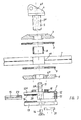
- the embodiment of the point holder 1 shown in FIG. 1 comprises a screw forming the pin 5 with a flat head with eye flap 4, onto which an upper plate 3 and a lower plate 6 with the interposition of the VSG plate 7 are screwed.
- the pin 5 and the tab 4 have longitudinal bores 5 a and 4 a .
- the pin 5 penetrates the hole 7 a of the VSG plate with the interposition of a glass protective sleeve 8, which consists for example of polyoxymethylene.
- the plate 6 contains holes 6 a , which can be used to inject a plastic into the space between the wall of the hole 7 a and the pin 5 before the clamping part 2 is mounted.
- 6 elastomeric rings 9 are arranged in a known manner for elastically damped mounting, but not for clamping the plate 7.
- the clamping part 2 is screwed to the pin 5 with the interposition of an elastomeric ring 10 by means of a hexagon screw 11 with an axial through hole 11 a .
- the clamping part 2 consists of a base part 12 and a cover part 13 which is screwed to the base part 12 by two screws 14 which are laterally offset to the axis.
- a conductor layer glass plate 15 is held between the clamping jaw 12 a of the base part 12 and the cover part 13 with the interposition of elastomeric layer body 16 without constraint.
- the base part 12 contains a connection chamber 17 which is closed in a moisture-tight manner by the cover part 13.
- the chamber 17 is connected via the opening 18 between the head of the screw 11 and the cover part 13 to the clamping space 19 between the cover part 13 and the clamping jaw 12 a of the base part 12.
- the conductor layer glass plate 15 carries a conductor layer on its outside (facing plate 7); the inner elastomeric layer 16 also carries an electrical contact conductor 20 which, when the plate 15 is clamped, contacts the contact 23 of the conductor layer 15 'and has a connecting line (not shown) which is led through the opening 18 into the connecting chamber 17.
- the power supply cable not shown, is also passed through the bores 4 a , 5 a , 11 a and the opening 18 into the connection chamber 17 and can be connected there to the connecting line of the contact 20 by means of plugs.
- This construction makes it possible to first mount the VSG plate, then screw on the clamping part 2 with the power supply cable hanging through the bore 11 a , mount the conductor layer glass plate and finally connect the power supply through the plug in the chamber 17.
- the connection chamber 17 is then closed by the cover 21.
- Figure 2 differs from that of Figure 1 in that the threaded pin 5 instead of the eye tab 4 carries a threaded bolt 22 with an axial bore 22 a .
- This holder can be screwed into a tubular rod with an internal thread by means of the bolt 22.
- This embodiment is suitable for attachment to railing posts, facades, ceilings and the like.
- Figure 3 shows the exploded view of the point holder according to Figure 1. It can be seen that this holder in different Terms can be varied.
- the eye flap 4 of the threaded pin 5 can be changed in shape and size.
- the plates 3 and 6 can 7 depending on the thickness of the plate Have diameter, and the clamping part 2 can according to the strength the plate 15 can be designed for other clamping widths.
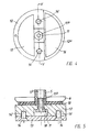
- Figure 4 shows the bottom view of the base part 12 of the clamping part 2 after removing the cover part 13.
- the base part 12 has a diametrical web, in which two threaded holes 14 'for the screws 14 for attaching the cover part and a central recess is included in the bearing surface for the head of the screw 11 and the opening 18 between the Connection chamber 17 and the terminal space 19 are formed.
- the transverse wall 5 c 5 has an axial bore b.
- the pin 5 has an external thread, onto which the top plate 3 and the bottom plate 6 are screwed with the interposition of the VSG plate 7 and the elastomer rings 9.
- the hemispherical head 25 of a hinge pin 26 is inserted, an elastomeric ring 27 being arranged between the head 25 and the transverse wall 5 c .
- the pin 5 has an internal thread in the upper area, into which a ring 28 is screwed.
- the ring 28 has an approximately hollow spherical zone-shaped bearing surface 28 a for the head 25 and in its upper region a frustoconical opening 28 b .
- the hinge pin 26, like the pin 22 in FIG. 2, is used for mounting on a support structure (not shown), but the plate 7 can be pivoted to a limited extent.
- DE 201 05 094.3 For further details of this joint, reference is made to DE 201 05 094.3.
- a mirror joint symmetrical to this joint, an identical swivel joint made of an approximately hemispherical head 30 formed at the end of a threaded bolt 29, an elastomeric ring 31 arranged between the head 30 and the transverse wall 5 c and an internal thread of the pin 5 screwed ring 32 included.
- the shaft of the hinge pin 29 is screwed into an axial bore 12 b of the base part 12, this connection being fixed by a lock nut 33.
- the hinge pins 26 and 29 have through bores 26 a and 29 a , which together with the bore 5 b form part of the conductor channel for the power supply to the plate 15.
- the clamping part 2 is essentially identical to that of the embodiment according to FIG. 2, with the exception, however, that a bore 12 c , which is led to the connection chamber 17, is provided for injecting a plastic for the purpose of watertight sealing of the plug connection. For the rest, reference is made to the description of FIG. 1 relating to the clamping part 2.
- Figure 7 shows a point holder similar to Figure 6, wherein however, the upper joint 25-28 has been eliminated and instead the Pin 5 as in the embodiment of Figure 1 an eye tab 4 for suspension of the plate by means of an articulated head and draw tube rod having.
- the clamping part 2 can in the same way as in Figure 6 and was not shown again in FIG. 7.
- FIG. 8 shows the use of the point holder shown in FIG. 1 in the case of a canopy inclinedly suspended on the wall 34 from a laminated safety glass plate in connection with a parallel, electrically connectable conductor layer glass plate 15.
- Two brackets 35 are screwed onto the wall 34 for mounting , the lower of which is shown.
- the eye tab 4 of the point holder close to the wall is connected in an articulated manner to a clevis pin 36 which, like the pin 5 , contains an axial bore 36 a as the conductor channel.
- the clevis pin 36 is screwed into the bracket 35 and fixed by the lock nut 37.
- the eye tab 4 of the point holder remote from the wall is similarly connected in an articulated manner to a perforated clevis pin 38 which is screwed into a tubular rod 39 with an internal thread.
- the pipe rod 39 is connected to the upper bracket (not shown) again via a clevis pin.
- one wire is connected via the lower console 35 through the holes 36 a , 4 a , 5 a , 11 a and the opening 18 to the connecting conductor of one end of the plate 15, and the other wire is connected via the upper console and the holes 39 a , 38 a , 4 a , 5 a , 11 a and 18 with the connecting conductor from the other end of the plate 15.
- FIG. 9 also shows a canopy made of the VSG plate 7 and the conductor layer glass plate 15 attached to the wall 34.
- This plate assembly is in turn mounted on the wall by means of brackets 35, only one of which is shown, and not as in the embodiment according to Figure 8 suspended, but supported from below, so that the tubular rod 39 and the clevis pin 36 are subjected to pressure.
- the plates 7 and 15 are not parallel to one another, but rather inclined at an angle of approximately 10 ° to one another, so that the plate 7 has an inclination of 10 °, while the plate 15 extends approximately horizontally. This is achieved by means of two spacer components 41 of different heights, which are inserted between the elastomeric disks 10 and the clamping parts 2.
- the spacer components 41 are screwed onto the pin 5 of the point holder 1 by means of tubular screws 42 with a hexagon head with the interposition of the elastomer rings 10. Then the chamber of the spacer components 41 is closed by a threaded cover 43 with a correspondingly inclined threaded bore 43 a . Finally, the base parts 12 of the clamping parts 2 are attached by means of pierced screws 11, as was explained above with reference to FIG. 5. After inserting the plate 15, the cover parts 13 are screwed on.
- the horizontal conductor layer glass plate 15 can transmit lighting information to the passers-by located under the canopy according to FIG. 9.
- the plate 15 can also serve to illuminate the wall 34.
- the angle between the two plates 7 and 15 can be increased beyond 10 °.
- the tubular rod 39, the clevis pin 36 and the eyelets 4 have corresponding holes 39 a , 36 a and 4 a .
- FIG. 10 differs from that according to FIG. 6 essentially in that the pin 5 of the point holder 1 contains a hemisphere joint only on the top side, while the clamping part 2 is rigidly screwed to the pin 5 analogously to the embodiment according to FIGS ,
- the elastomeric ring 10 has been omitted and instead an abutment ring 12 d is formed on the base part 12, with which the base part 12 is supported directly on the plate 6.
- FIG. 11 shows a first embodiment of the point holder 1 according to the invention with an integrated clamping part 2.
- This embodiment differs from that according to FIG. 10 in that the lower plate of the point holder and the base part of the clamping part 2 form an integral part and the contact ring 12 d is omitted. This results in greater compactness and stability compared to the embodiment according to FIG. 10.
- FIGS. 10 and 11 show the conductor layer glass plates 15 which are currently preferably used, in which the conductor layer is not arranged on an outer surface of the carrier plate as in the other embodiments, but inside on one of the two panes forming the plate. Accordingly, the contact 23 a is arranged on the plate face. Conductor layers can also be provided on the inside of both panes, which are electrically insulated from one another by the cast resin layer connecting the panes.
- FIG. 12 Another point holder 1 with an integrated clamping part is shown in FIG. 12.
- the base part is integrally formed on the pin 5.
- the cover plate 13 is omitted. Only the closure cover 21 is provided for access to the connection chamber 17.
- the pin 5 has a threaded hole 5 c which is stepped in relation to its axial bore 5 a and into which a screw 44 carrying the eye plate 4 is screwed.
- the upper plate 3 is screwed onto the pin 5 from the side of the tab 4 after the plates 7, 15 have been inserted.
- the conductor layer glass plate 15 is either - as shown - directly or with a thin layer in the plate edge region (not shown) on the VSG plate 7.
- the hole 5 d serves to lead through the connecting conductor for the conductor layer glass plate 15.
- This embodiment has an even further reduced overall height compared to that according to FIG. 11, since the clamping jaw 12a of the base part has been omitted.
- This point holder like that according to FIG. 1, is provided for plate suspension on a tension rod system.
- the embodiment according to FIG. 13 differs from that according to FIG. 12 only in that the step-widened bore 5 c is omitted and instead the axial bore 5 a has a threaded part at the upper end into which the threaded bolt 22 is screwed.
- This point holder with an integrated clamping part can be screwed onto posts, ceilings and the like by means of bolts 22.
- FIG. 14 differs from that according to FIG. 12 in that instead of the pin 5 screwed eyebolt 44 a hinge pin 26 with approximately hemispherical Head 25 in the described for the embodiment of Figure 6 Is articulated in the pin 5. Furthermore the connection chamber 17 is not eccentric, but centric contained in the pin 5 or its base part and by the Cover 21 closed. Also in this embodiment with an integrated Clamping part and swiveling storage are the plates 7 and 15 together. A locking pin 45 on the plate 3 prevents a slipping of the conductor layer glass plate 15 as a result of being too weak Clamping.
- Conductor layer glass plate 15 on the mounting device 4,22,26 15 is an embodiment the point holder 1 with integrated clamping part 2, in which the conductor layer glass plate 15 on the threaded bolt 22 as a mounting device facing side is arranged.
- the base part forms at the same time the one plate of the point holder as in the version 11, wherein the clamping part 2 by means of screw 46 with the Pin 5 is screwed, which is integrally formed on the plate 3. at In this embodiment, the conductor channel no longer leads through the Point holder 1, which contributes to simplification.
Landscapes
- Engineering & Computer Science (AREA)
- Architecture (AREA)
- Civil Engineering (AREA)
- Structural Engineering (AREA)
- Physics & Mathematics (AREA)
- Electromagnetism (AREA)
- Securing Of Glass Panes Or The Like (AREA)
- Joining Of Glass To Other Materials (AREA)
- Materials For Medical Uses (AREA)
- Adhesive Tapes (AREA)
- Load-Bearing And Curtain Walls (AREA)
- Window Of Vehicle (AREA)
Abstract
Description
Claims (16)
- Punkthalter für eine gelochte Verbundsicherheitsglasplatte mit einem Teller (3) auf der einen Seite, einem Teller (6) auf der anderen Seite der Platte (7) und einem die Teller verbindenden, das Plattenloch (7a) durchstoßenden Zapfen (5), wobei der Punkthalter (1) auf einer Seite eine Einrichtung (4; 22; 26) für seine Montage an einer Tragkonstruktion hat,
dadurch gekennzeichnet, daß der Punkthalter (1) auf einer Seite der Platte (7) einen angebrachten oder integrierten Klemmteil (2) für eine Leiterschicht platte (15) aufweist und für die Stromversorgung dieser Platte ein Leiterkanal durch die Montageeinrichtung (4; 22; 26) bis in den Klemmteil (2) geführt ist. - Punkthalter nach Anspruch 1, dadurch gekennzeichnet, daß der Klemmteil (2) als separater Halter an den Punkthalter (1) angeschraubt und die Leiterschichtplatte (15) zwischen den beiden Klemmbacken (12a,13) des Klemmteils (2) zwängungsfrei geführt ist.
- Punkthalter nach Anspruch 1, dadurch gekennzeichnet, daß ein Teller (6) des Punkthalters (1) zugleich eine Klemmbacke des Klemmteils (2) ist.
- Punkthalter nach Anspruch 1, dadurch gekennzeichnet, daß die Leiterschichtplatte (15) zwischen einem Teller des Punkthalters (1) und der Verbundsicherheitsglasplatte (7) zwängungsfrei geführt ist.
- Punkthalter nach einem der Ansprüche 1 bis 4, dadurch gekennzeichnet, daß der Klemmteil (2) eine Anschlußkammer (17) enthält, die mit dem Leiterkanal (5a) und dem Raum (19) zwischen den Klemmbacken (12a,13) verbunden ist.
- Punkthalter nach Anspruch 5, dadurch gekennzeichnet, daß die Anschlußkammer (17) durch einen Deckel (21) feuchtigkeitsdicht verschließbar ist.
- Punkthalter nach Anspruch 5, dadurch gekennzeichnet, daß die Anschlußkammer (17) mit der Außenseite durch eine Bohrung (12c) verbunden ist, durch die die Kammer mit einem Einspritz-Kunststoff ausgefüllt werden kann.
- Punkthalter nach einem der Ansprüche 1 bis 7, dadurch gekennzeichnet, daß der Klemmteil (2) auf der der Montageeinrichtung (4;22;26) abgewandten Seite des Punkthalters (1) angeordnet ist.
- Punkthalter nach einem der Ansprüche 1 bis 7, dadurch gekennzeichnet, daß der Klemmteil (2) und die Montageeinrichtung (4;22;26) auf der gleichen Seite des Punkthalters (1) angeordnet sind.
- Punkthalter nach Anspruch 1 oder 2, dadurch gekennzeichnet, daß der Klemmteil (2) über ein Abstandsbauteil (41) an dem Punkthalter (1) angebracht ist.
- Punkthalter nach Anspruch 10, dadurch gekennzeichnet, daß die Höhe des Abstandsbauteils (41) einstellbar ist.
- Punkthalter nach einem der Ansprüche 1 bis 11, dadurch gekennzeichnet, daß die Montageeinrichtung eine Augenlasche (4) an dem Punkthalter (1) und ein Gewinderohrgestänge (36; 38,39) umfaßt.
- Punkthalter nach Anspruch 1, dadurch gekennzeichnet, daß der Klemmteil (2) mit dem Punkthalter (1) gelenkig verbunden ist.
- Punkthalter nach einem der Ansprüche 1 bis 13, dadurch gekennzeichnet, daß der Punkthalter (1) und/oder der Klemmteil (2) Gummipolster mit linienförmigem Kontakt zur Glasplatte (7; 15) aufweist.
- Punkthalter nach einem der Ansprüche 1 bis 14, dadurch gekennzeichnet, daß die Leiterschichtplatte (15) aus zwei verbundenen Scheiben besteht und wenigstens eine der beiden Scheiben innenseitig eine elektrische Leiterschicht trägt.
- Glasplattenaggregat aus einer gelochten Verbundsicherheitsglasplatte (7), in deren Löchern (7a) Punkthalter (1) nach einem der Ansprüche 1 bis 15 montiert sind, und einer ungelochten Leiterschicht-Glasplatte (15), die durch die Klemmteile (2) der Punkthalter (1) gehalten ist.
Applications Claiming Priority (2)
| Application Number | Priority Date | Filing Date | Title |
|---|---|---|---|
| DE10122370 | 2001-05-09 | ||
| DE10122370A DE10122370C2 (de) | 2001-05-09 | 2001-05-09 | Punkthalter |
Publications (2)
| Publication Number | Publication Date |
|---|---|
| EP1256687A1 true EP1256687A1 (de) | 2002-11-13 |
| EP1256687B1 EP1256687B1 (de) | 2005-10-05 |
Family
ID=7684058
Family Applications (1)
| Application Number | Title | Priority Date | Filing Date |
|---|---|---|---|
| EP02008907A Expired - Lifetime EP1256687B1 (de) | 2001-05-09 | 2002-04-20 | Punkthalter |
Country Status (3)
| Country | Link |
|---|---|
| EP (1) | EP1256687B1 (de) |
| AT (1) | ATE306006T1 (de) |
| DE (2) | DE10122370C2 (de) |
Cited By (2)
| Publication number | Priority date | Publication date | Assignee | Title |
|---|---|---|---|---|
| WO2005071183A1 (de) * | 2004-01-26 | 2005-08-04 | Ingo Maurer Gmbh | Fassadenverkleidung |
| CN102128189A (zh) * | 2010-12-31 | 2011-07-20 | 常州天合光能有限公司 | 太阳能组件平面安装固定装置 |
Families Citing this family (4)
| Publication number | Priority date | Publication date | Assignee | Title |
|---|---|---|---|---|
| DE10327752B3 (de) * | 2003-06-10 | 2004-11-04 | Joachim Orbach | Vorrichtung zur Halterung einer Platte |
| DE10304334B3 (de) * | 2003-02-04 | 2004-09-23 | SWS Gesellschaft für Glasbaubeschläge mbH | Punkthalter |
| DE10334227B3 (de) | 2003-07-28 | 2005-02-24 | SWS Gesellschaft für Glasbaubeschläge mbH | Punkthalter |
| DE102017111417B4 (de) | 2017-05-24 | 2025-11-06 | Treppenmeister Gmbh | Punkthalter |
Citations (3)
| Publication number | Priority date | Publication date | Assignee | Title |
|---|---|---|---|---|
| US5138804A (en) * | 1985-07-31 | 1992-08-18 | Pilkington Plc. | Structural glass unit |
| WO1999063193A1 (de) * | 1998-06-04 | 1999-12-09 | Dorma Gmbh + Co. Kg | Befestigungsvorrichtung für eine glasplatte an einer gebäudeseitigen halterung |
| EP0965721A1 (de) * | 1998-06-17 | 1999-12-22 | Glas Trösch Holding AG | Befestigung für Isolierglaselement |
Family Cites Families (3)
| Publication number | Priority date | Publication date | Assignee | Title |
|---|---|---|---|---|
| DE29711973U1 (de) * | 1997-07-08 | 1998-11-05 | Firma Glas-Platz, 51580 Reichshof | Elektrische Vorrichtung, elektrisches Gerät bzw. Beleuchtungsvorrichtung |
| DE19933967C2 (de) * | 1999-07-20 | 2002-11-07 | Marina Orbach | Punkthaltersystem |
| DE10000417C2 (de) * | 1999-09-13 | 2002-08-29 | Dorma Gmbh & Co Kg | Verbindungsbrücke zur Verbindung von Glaswandsegmenten |
-
2001
- 2001-05-09 DE DE10122370A patent/DE10122370C2/de not_active Expired - Fee Related
-
2002
- 2002-04-20 AT AT02008907T patent/ATE306006T1/de not_active IP Right Cessation
- 2002-04-20 EP EP02008907A patent/EP1256687B1/de not_active Expired - Lifetime
- 2002-04-20 DE DE50204432T patent/DE50204432D1/de not_active Expired - Fee Related
Patent Citations (3)
| Publication number | Priority date | Publication date | Assignee | Title |
|---|---|---|---|---|
| US5138804A (en) * | 1985-07-31 | 1992-08-18 | Pilkington Plc. | Structural glass unit |
| WO1999063193A1 (de) * | 1998-06-04 | 1999-12-09 | Dorma Gmbh + Co. Kg | Befestigungsvorrichtung für eine glasplatte an einer gebäudeseitigen halterung |
| EP0965721A1 (de) * | 1998-06-17 | 1999-12-22 | Glas Trösch Holding AG | Befestigung für Isolierglaselement |
Cited By (5)
| Publication number | Priority date | Publication date | Assignee | Title |
|---|---|---|---|---|
| WO2005071183A1 (de) * | 2004-01-26 | 2005-08-04 | Ingo Maurer Gmbh | Fassadenverkleidung |
| CN100425782C (zh) * | 2004-01-26 | 2008-10-15 | 英戈·毛雷尔有限责任公司 | 正面覆盖物 |
| US7454866B2 (en) | 2004-01-26 | 2008-11-25 | Ingo Maurer Gmbh | Façade covering |
| CN102128189A (zh) * | 2010-12-31 | 2011-07-20 | 常州天合光能有限公司 | 太阳能组件平面安装固定装置 |
| CN102128189B (zh) * | 2010-12-31 | 2012-07-25 | 常州天合光能有限公司 | 太阳能组件平面安装固定装置 |
Also Published As
| Publication number | Publication date |
|---|---|
| DE10122370C2 (de) | 2003-06-12 |
| EP1256687B1 (de) | 2005-10-05 |
| DE50204432D1 (de) | 2005-11-10 |
| ATE306006T1 (de) | 2005-10-15 |
| DE10122370A1 (de) | 2002-11-28 |
Similar Documents
| Publication | Publication Date | Title |
|---|---|---|
| EP0446875B1 (de) | Schutzgehäuse für optische Geräte | |
| DE29714096U1 (de) | Verbindersystem | |
| DE3420696C1 (de) | Klemmbeschlag für die Befestigung und/oder Verbindung von Glasscheiben, insbesondere für Fassadenplatten aus Einscheibensicherheitsglas | |
| DE3153394C2 (de) | ||
| DE10122370C2 (de) | Punkthalter | |
| DE10044791A1 (de) | Anbaugehäuse | |
| DE20107806U1 (de) | Punkthalter | |
| EP0965721A1 (de) | Befestigung für Isolierglaselement | |
| DE2036853A1 (de) | Lichtsignalgeber, insbesondere fur den Straßenverkehr 100000 | |
| DE19933967C2 (de) | Punkthaltersystem | |
| DE3326618A1 (de) | Schraeglagenfuehler | |
| EP1408190A1 (de) | Türbandanordnung | |
| EP1175543B1 (de) | Verbindungsbrücke zur verbindung von glaswandsegmenten, die mit solarpaneelen ausgestattet sind | |
| DE102022131236A1 (de) | Elektrisches Endgerät, Herstellungsverfahren und Justierungsverfahren | |
| EP2956708B1 (de) | Leuchtenstele | |
| DE102007008328A1 (de) | Mast | |
| EP0283897A2 (de) | Stützisolator | |
| DE102018106443B3 (de) | Scharnier | |
| DE1615067A1 (de) | Druckfeste elektrische Durchfuehrung | |
| EP0979971A1 (de) | Leuchtengehäuse mit einer Einrichtung zum Druckausgleich | |
| DE19950932B4 (de) | Zündkerze für eine Brennkraftmaschine | |
| DE29911296U1 (de) | Klemmhaltersystem | |
| DE29817352U1 (de) | Plattenhaltersystem | |
| EP1514000B1 (de) | Verbindungssystem f r zwei k rper, von denen mindestens einer zwei hohlkammern aufweist | |
| DE202025104167U1 (de) | Leuchtenhalterung zur Befestigung einer Leuchte |
Legal Events
| Date | Code | Title | Description |
|---|---|---|---|
| PUAI | Public reference made under article 153(3) epc to a published international application that has entered the european phase |
Free format text: ORIGINAL CODE: 0009012 |
|
| AK | Designated contracting states |
Kind code of ref document: A1 Designated state(s): AT BE CH CY DE DK ES FI FR GB GR IE IT LI LU MC NL PT SE TR |
|
| AX | Request for extension of the european patent |
Free format text: AL;LT;LV;MK;RO;SI |
|
| 17P | Request for examination filed |
Effective date: 20021218 |
|
| AKX | Designation fees paid |
Designated state(s): AT BE CH CY DE DK ES FI FR GB GR IE IT LI LU MC NL PT SE TR |
|
| GRAP | Despatch of communication of intention to grant a patent |
Free format text: ORIGINAL CODE: EPIDOSNIGR1 |
|
| GRAS | Grant fee paid |
Free format text: ORIGINAL CODE: EPIDOSNIGR3 |
|
| GRAA | (expected) grant |
Free format text: ORIGINAL CODE: 0009210 |
|
| AK | Designated contracting states |
Kind code of ref document: B1 Designated state(s): AT BE CH CY DE DK ES FI FR GB GR IE IT LI LU MC NL PT SE TR |
|
| PG25 | Lapsed in a contracting state [announced via postgrant information from national office to epo] |
Ref country code: IE Free format text: LAPSE BECAUSE OF FAILURE TO SUBMIT A TRANSLATION OF THE DESCRIPTION OR TO PAY THE FEE WITHIN THE PRESCRIBED TIME-LIMIT Effective date: 20051005 Ref country code: IT Free format text: LAPSE BECAUSE OF FAILURE TO SUBMIT A TRANSLATION OF THE DESCRIPTION OR TO PAY THE FEE WITHIN THE PRESCRIBED TIME-LIMIT;WARNING: LAPSES OF ITALIAN PATENTS WITH EFFECTIVE DATE BEFORE 2007 MAY HAVE OCCURRED AT ANY TIME BEFORE 2007. THE CORRECT EFFECTIVE DATE MAY BE DIFFERENT FROM THE ONE RECORDED. Effective date: 20051005 Ref country code: FI Free format text: LAPSE BECAUSE OF FAILURE TO SUBMIT A TRANSLATION OF THE DESCRIPTION OR TO PAY THE FEE WITHIN THE PRESCRIBED TIME-LIMIT Effective date: 20051005 Ref country code: GB Free format text: LAPSE BECAUSE OF FAILURE TO SUBMIT A TRANSLATION OF THE DESCRIPTION OR TO PAY THE FEE WITHIN THE PRESCRIBED TIME-LIMIT Effective date: 20051005 Ref country code: NL Free format text: LAPSE BECAUSE OF FAILURE TO SUBMIT A TRANSLATION OF THE DESCRIPTION OR TO PAY THE FEE WITHIN THE PRESCRIBED TIME-LIMIT Effective date: 20051005 |
|
| REG | Reference to a national code |
Ref country code: GB Ref legal event code: FG4D Free format text: NOT ENGLISH |
|
| REG | Reference to a national code |
Ref country code: CH Ref legal event code: EP |
|
| REG | Reference to a national code |
Ref country code: IE Ref legal event code: FG4D Free format text: LANGUAGE OF EP DOCUMENT: GERMAN |
|
| REF | Corresponds to: |
Ref document number: 50204432 Country of ref document: DE Date of ref document: 20051110 Kind code of ref document: P |
|
| PG25 | Lapsed in a contracting state [announced via postgrant information from national office to epo] |
Ref country code: SE Free format text: LAPSE BECAUSE OF FAILURE TO SUBMIT A TRANSLATION OF THE DESCRIPTION OR TO PAY THE FEE WITHIN THE PRESCRIBED TIME-LIMIT Effective date: 20060105 Ref country code: DK Free format text: LAPSE BECAUSE OF FAILURE TO SUBMIT A TRANSLATION OF THE DESCRIPTION OR TO PAY THE FEE WITHIN THE PRESCRIBED TIME-LIMIT Effective date: 20060105 Ref country code: GR Free format text: LAPSE BECAUSE OF FAILURE TO SUBMIT A TRANSLATION OF THE DESCRIPTION OR TO PAY THE FEE WITHIN THE PRESCRIBED TIME-LIMIT Effective date: 20060105 |
|
| PG25 | Lapsed in a contracting state [announced via postgrant information from national office to epo] |
Ref country code: ES Free format text: LAPSE BECAUSE OF FAILURE TO SUBMIT A TRANSLATION OF THE DESCRIPTION OR TO PAY THE FEE WITHIN THE PRESCRIBED TIME-LIMIT Effective date: 20060116 |
|
| NLV1 | Nl: lapsed or annulled due to failure to fulfill the requirements of art. 29p and 29m of the patents act | ||
| PG25 | Lapsed in a contracting state [announced via postgrant information from national office to epo] |
Ref country code: PT Free format text: LAPSE BECAUSE OF FAILURE TO SUBMIT A TRANSLATION OF THE DESCRIPTION OR TO PAY THE FEE WITHIN THE PRESCRIBED TIME-LIMIT Effective date: 20060306 |
|
| PG25 | Lapsed in a contracting state [announced via postgrant information from national office to epo] |
Ref country code: AT Free format text: LAPSE BECAUSE OF NON-PAYMENT OF DUE FEES Effective date: 20060420 |
|
| PG25 | Lapsed in a contracting state [announced via postgrant information from national office to epo] |
Ref country code: CH Free format text: LAPSE BECAUSE OF NON-PAYMENT OF DUE FEES Effective date: 20060430 Ref country code: BE Free format text: LAPSE BECAUSE OF NON-PAYMENT OF DUE FEES Effective date: 20060430 Ref country code: LI Free format text: LAPSE BECAUSE OF NON-PAYMENT OF DUE FEES Effective date: 20060430 Ref country code: MC Free format text: LAPSE BECAUSE OF NON-PAYMENT OF DUE FEES Effective date: 20060430 |
|
| GBV | Gb: ep patent (uk) treated as always having been void in accordance with gb section 77(7)/1977 [no translation filed] |
Effective date: 20051005 |
|
| REG | Reference to a national code |
Ref country code: IE Ref legal event code: FD4D |
|
| PLBE | No opposition filed within time limit |
Free format text: ORIGINAL CODE: 0009261 |
|
| STAA | Information on the status of an ep patent application or granted ep patent |
Free format text: STATUS: NO OPPOSITION FILED WITHIN TIME LIMIT |
|
| 26N | No opposition filed |
Effective date: 20060706 |
|
| PG25 | Lapsed in a contracting state [announced via postgrant information from national office to epo] |
Ref country code: FR Free format text: LAPSE BECAUSE OF FAILURE TO SUBMIT A TRANSLATION OF THE DESCRIPTION OR TO PAY THE FEE WITHIN THE PRESCRIBED TIME-LIMIT Effective date: 20061020 |
|
| PG25 | Lapsed in a contracting state [announced via postgrant information from national office to epo] |
Ref country code: DE Free format text: LAPSE BECAUSE OF NON-PAYMENT OF DUE FEES Effective date: 20061101 |
|
| EN | Fr: translation not filed | ||
| REG | Reference to a national code |
Ref country code: CH Ref legal event code: PL |
|
| BERE | Be: lapsed |
Owner name: SWS G.- FUR GLASBAUBESCHLAGE MBH Effective date: 20060430 |
|
| PG25 | Lapsed in a contracting state [announced via postgrant information from national office to epo] |
Ref country code: TR Free format text: LAPSE BECAUSE OF FAILURE TO SUBMIT A TRANSLATION OF THE DESCRIPTION OR TO PAY THE FEE WITHIN THE PRESCRIBED TIME-LIMIT Effective date: 20051005 Ref country code: LU Free format text: LAPSE BECAUSE OF NON-PAYMENT OF DUE FEES Effective date: 20060420 |
|
| PG25 | Lapsed in a contracting state [announced via postgrant information from national office to epo] |
Ref country code: FR Free format text: LAPSE BECAUSE OF FAILURE TO SUBMIT A TRANSLATION OF THE DESCRIPTION OR TO PAY THE FEE WITHIN THE PRESCRIBED TIME-LIMIT Effective date: 20051005 Ref country code: CY Free format text: LAPSE BECAUSE OF FAILURE TO SUBMIT A TRANSLATION OF THE DESCRIPTION OR TO PAY THE FEE WITHIN THE PRESCRIBED TIME-LIMIT Effective date: 20051005 |