EP1256426B1 - Dispositif pour répandre des particules, particulièrement copeaux de bois, fibres de bois ou semblable sur une bande transporteuse - Google Patents
Dispositif pour répandre des particules, particulièrement copeaux de bois, fibres de bois ou semblable sur une bande transporteuse Download PDFInfo
- Publication number
- EP1256426B1 EP1256426B1 EP02009113A EP02009113A EP1256426B1 EP 1256426 B1 EP1256426 B1 EP 1256426B1 EP 02009113 A EP02009113 A EP 02009113A EP 02009113 A EP02009113 A EP 02009113A EP 1256426 B1 EP1256426 B1 EP 1256426B1
- Authority
- EP
- European Patent Office
- Prior art keywords
- scattering
- rotational speed
- rollers
- delivery region
- material delivery
- Prior art date
- Legal status (The legal status is an assumption and is not a legal conclusion. Google has not performed a legal analysis and makes no representation as to the accuracy of the status listed.)
- Expired - Lifetime
Links
Images


Classifications
-
- B—PERFORMING OPERATIONS; TRANSPORTING
- B27—WORKING OR PRESERVING WOOD OR SIMILAR MATERIAL; NAILING OR STAPLING MACHINES IN GENERAL
- B27N—MANUFACTURE BY DRY PROCESSES OF ARTICLES, WITH OR WITHOUT ORGANIC BINDING AGENTS, MADE FROM PARTICLES OR FIBRES CONSISTING OF WOOD OR OTHER LIGNOCELLULOSIC OR LIKE ORGANIC MATERIAL
- B27N3/00—Manufacture of substantially flat articles, e.g. boards, from particles or fibres
- B27N3/08—Moulding or pressing
- B27N3/10—Moulding of mats
- B27N3/14—Distributing or orienting the particles or fibres
Definitions
- the invention relates to a grit plant for spreading glued sprinkling material, in particular wood chips, wood fibers o. The like.
- a scattering belt conveyor to form spreading mats in the production of particleboard, fiberboard or the like.
- Wood-based panels with a grit hopper with a dosing unit for spreading Scattering on a scattering roller conveyor arranged above the Streuand meticulousers with at least one fine-material discharge area and a downstream coarse material discharge area.
- a grit plant whose Streuwalzen letters is composed of a Streuwalzenoberdeck and a Streuwalzenunterdeck, which is located in the last third below the Streuwalzenoberdecks.
- the Spreader roll top deck first casts fines onto the spreader belt conveyor for topping, while the spreader top deck, together with the spreader roll bottom deck, casts a mixture of fines and coarse material to form the middle layer.
- a mixture of coarse material and fine material is then first thrown off to complete the middle layer and then only fines to form the overhead covering layer.
- the invention has for its object to provide a grit system of the embodiment described above, with which the middle layer of the grit mats can be produced with a particularly fine distribution of the fine material as a binder to press it from wood panels with increased transverse tensile strength in a downstream continuous press or cycle press can.
- the invention in a generic grit plant characterized in that the coarse material discharge area has at least one circulating roller rotating in comparison to the scattering rollers of the fine material discharge area by a predetermined amount of increased rotational speed.
- a cover layer or the like can be applied from essentially fine material onto the scattering belt conveyor and subsequently onto this covering layer in the manner described a middle layer of a fine material / coarse mixture.
- the grit plant according to the invention as a middle-layer scattering machine, ie first a lower cover layer is applied to the scatter belt conveyor with a separate, upstream grit plant. Subsequently, this covering layer passes through the spreading material system according to the invention on the scatter belt conveyor. There, an intermediate layer of essentially fine material is first sprinkled onto the cover layer in the fines discharge area.
- the fine material / coarse mixture is sprinkled onto the intermediate layer to form the middle layer.
- a further middle layer or middle layer half and possibly a further intermediate layer can be applied, before then optionally an upper cover layer is applied in a final scattering process.
- the discarding effect achieved according to the teaching of the invention is optimized according to a particular proposal by arranging a coarse material discharge device below the scattering roller of the coarse material discharge area which revolves at an increased rotational speed, the discharge direction of which is opposite to the conveying direction of the scattering roller train and consequently of the scattering material back under the fine material. Throwing area is directed and consequently there fine material is dropped on the thrown off there and, as it were back conveyed coarse material to form the intimate fines / coarse mixture.
- the invention provides that the coarse material discharge device has a GroGgutleit Structure which is arranged at a predetermined distance to the rotating at an increased rotational speed scattering roller and having a roll circumference in the direction below the fines discharge area following surface curvature.
- the invention provides that the coarse material discharge area with several by a predetermined amount Has rotating speed circulating scattering rollers with coarse material discharge devices or Grobgutleit vom assigned on the underside.
- a scattering roller can be arranged between the rotating with speed of rotation rotating scattering rollers of the coarse material discharge area, which rotates with the rotational speed of the scattering rollers of the fines discharge area, on the one hand to allow further fines discharge, on the other hand to reduce an overlap of the discarding curves for the coarse material or to avoid.
- the distance between the scattering rollers of the fine material discharge area may increase at least in the end region of the fine material discharge area in order to achieve the discharge of only particularly fine fine material for the top layer formation at the beginning of the fine material discharge area, and at the end of the fine material discharge area to allow the discharge of fine material and fine coarse material at the beginning of the middle layer formation.
- the metering unit with a controllable metering belt has a metering roller, whose rotational speed by a predetermined amount, for. B. 2 to 12 times higher than the rotational speed of the scattering rollers of the fines discharge area is selected to ensure that the formed on the single deck Streuwalzen Identification discarded grit reaches the end of the Streuwalzen Identification and consequently also the coarse material discharge area with the faster-running scattering rollers.
- Foreign matter such as too coarse material, metal parts, glue, lumps o. The like. Are discharged at the end of the Streuwalzen Identification to a foreign substance discharge conveyor.
- the circulating with high rotational speed or speed scatter rollers in the coarse material discharge area in about a 5-fold to 40-fold higher rotational speed or speed than the scattering rollers of the fine material discharge area.
- the scattering rollers of the fine-material discharge area may have an optionally variable speed of approximately 5 revolutions per minute to 25 revolutions per minute.
- the scattering rollers revolving at increased rotational speed in the coarse material discharge region have an optionally variable rotational speed or rotational speed of approximately 150 revolutions per minute to 200 revolutions per minute.
- the invention proposes that the adjustable rotational speed of the scattering rollers of the fine material discharge area and / or the coarse material discharge area is coupled to the adjustable speed of the metering belt. If, for example, the speed of the metering belt is increased by a predetermined factor during operation of the system, the rotational speed of the spreading rollers is automatically increased by this factor.
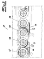
- a grit plant for spreading glued grit 1, in particular wood chips, wood fibers o. The like.
- This grit plant has a grit hopper 3 with a metering unit consisting of a metering belt 4 and a metering roller 5 for spreading grit 1 on a scattering roller train 6 arranged above the scatter belt conveyor 2 - also called a spreading head - with at least one fines discharge area 7 and a downstream coarse material discharge area 8 on.
- the scattering roller train 6 and the scattering belt conveyor 2 located underneath are arranged substantially horizontally.
- the scattering rollers 9 of the Streuwalzen No 6 have the same direction of rotation.
- the scattering rollers 9 of the fine material discharge area 7 rotate at a variable speed D 1 .
- the coarse material discharge area 8 has in the embodiment two with in comparison to the scattering rollers 9 of the fine material discharge area 7 by a predetermined amount of increased rotational speed or speed D 2 circulating spreader rollers 10. Below each of the rotating with increased rotational speed or speed D 2 spreader rollers 10th a coarse material discharge device 11 is arranged, the discharge direction is directed against the conveying direction of the scattering material 1 and the Streuwalzen pieces 6 back under the fines discharge area 7. In this way, a Streuwalzen puzzle 6 can be realized as a single deck.
- Fig. 1 shows the grit plant according to the invention in a mode of operation for scattering a cover layer DS and a middle layer MS arranged thereon with a single Streuwalzen Avenue 6.
- a grit plant for example, one or more not shown further grit systems for applying a further middle layer and / or a connect upper cover layer.
- the grit plant in the mode of operation shown in FIG. 4 is used, as it were, as a middle-layer machine for spreading esp. A middle layer.
- a cover layer DS is first sprinkled onto the scatter belt conveyor 2 from an upstream grit plant (not shown).
- An intermediate layer ZS made of fine material is then applied to this lower covering layer DS with the spreading material system shown in FIG. 4.
- the actual Middle layer MS applied from the fine / coarse mixture.
- a further middle layer or a further intermediate layer can then be applied again in an additional grit plant, not shown, and then an upper cover layer can be applied again in an equally separate grit plant. This is not shown.
- the grit plant as a middle layer machine thus arise per middle layer practically two zones.
- the intermediate layer ZS is formed, to which the actual middle layer MS adjoins. This has the advantage that z. B.
- the upper middle layer of the upper cover layer is covered by interposition of the intermediate layer clean, ie coarse chips are really in the middle of the finished plate and do not paint on the optionally coated plate surface. In addition, a trickling through of cover layer material in the middle layer is prevented.
- the coarse material discharge devices 11 each have a coarse material guide surface 12, which is arranged at a predetermined distance a from the spreading roller 10 which revolves at an increased rotational speed and has a surface curvature following the roller circumference in the direction below the fine material discharge region 7.
- a spreader roller 13 is arranged, which rotates with the rotational speed or speed D 1 of the spreader rollers 9 of the fine material discharge area 7.
- the distance between the scattering rollers 9 of the fine material discharge area 7 may increase at least in the end area of the fine material discharge area 7, which is not shown.
- the metering unit has a metering roller 5, the rotational speed of which can be set by a predetermined amount higher than the rotational speed of the scattering rollers 9 of the fines discharge area 7 so that the discarded litter 1 reaches the end of the Streuwalzen Identification 6, at least the coarse material discharge area 8.
- the metering roller 5 rotates at a speed of about 60 revolutions per minute (rpm), namely against the direction of rotation of the scattering rollers 9, 10, 13 of the scattering roller train. Because both the "slow" spreader rollers 9 and 13 and the “fast” spreader rollers 10 all rotate in the same direction.
- the spreader rollers 9 of the fine material discharge area rotate at a speed D 1 of approximately 5 rpm to 25 rpm, while the spreader rollers 10 rotate at a speed D 2 of 150 rpm to 200 rpm. D. h.,
- the rotational speed D 2 is higher by a factor of 6 to 40 than the rotational speed D 1 .
- the spreader rollers 9 and the spreader rollers 13 each rotate at the same speed D 1 .
- the diameter of all scattering rollers 9, 10, 13 is identical and is in the exemplary embodiment in about 90 mm.
- the distance A of the scattering roller train 6 from the scatter belt conveyor 2 or from the scattering material scattered on the scatter belt conveyor amounts to approximately 400 mm to 500 mm.
- Both the belt speed V B of the metering belt 4 and the rotational speeds D 1 , D 2 of the spreader rollers 9, 10, 13 can be varied. It is the rotational speed of the scattering rollers 9 and / or the spreader rolls 10 as it were linearly coupled to the tape speed V B. D.
- the speed of the spreader rollers is increased accordingly by this factor. This preferably applies both to the rotational speed D 1 of the scattering rollers 9 and optionally 13 and also to the rotational speed D 2 of the scattering rollers 10.
Landscapes
- Life Sciences & Earth Sciences (AREA)
- Engineering & Computer Science (AREA)
- Manufacturing & Machinery (AREA)
- Wood Science & Technology (AREA)
- Forests & Forestry (AREA)
- Dry Formation Of Fiberboard And The Like (AREA)
- Fodder In General (AREA)
- Debarking, Splitting, And Disintegration Of Timber (AREA)
Claims (11)
- Installation d'épandage de produits pour l'épandage de produits d'épandage, notamment de copeaux de bois, fibres de bois ou similaires, sur un convoyeur à bande d'épandage en formant des nappes d'épandage au cours de la fabrication de panneaux de particules, plaques de fibres ou plaques de matériau à base de bois similaires,
comportant un silo de produit d'épandage équipé d'une unité de dosage pour répandre du produit d'épandage sur un train de laminoir d'épandage disposé au dessus du convoyeur à bande d'épandage comprenant au moins une zone de projection de produit fin et une zone de projection de produit grossier installée en aval de celle-ci,
dans laquelle la zone de projection de produit grossier (8) comporte au moins un cylindre d'épandage (10) tournant à une vitesse de rotation accrue d'une valeur prédéfinie par rapport aux cylindres d'épandage (9) de la zone de projection de produit fin (7), caractérisée en ce que la zone de projection de produit grossier rejette le produit grossier sur le dessous du cylindre à l'encontre du sens de convoyage du produit d'épandage dans la zone de projection de produit fin (7). - Installation d'épandage de produits selon la revendication 1, caractérisée en ce que, en dessous du cylindre d'épandage (10) tournant à une vitesse de rotation accrue de la zone de projection de produit grossier (8), est disposé un dispositif de projection de produit grossier (11) dont le sens de projection est orienté à l'encontre du sens de convoyage du train de laminoir d'épandage (6) en retrait sous la zone de projection de produit fin (7).
- Installation d'épandage de produits selon la revendication 1 ou 2, caractérisée en ce que le dispositif de projection de produit grossier (11) comporte une surface conductrice de produit grossier (12) qui est disposée à distance prescrite (a) du cylindre d'épandage (10) tournant à une vitesse de rotation accrue et une courbure surfacique suivant la circonférence du cylindre dans le sens du dessous de la zone de projection de produit fin (7).
- Installation d'épandage de produits selon une des revendications 1 à 3, caractérisée en ce que la zone de projection de produit grossier (8) comporte plusieurs cylindres d'épandage (10) tournant à une vitesse accrue à raison d'une valeur prescrite avec des dispositifs de projection de produit grossier (11), par exemple des surfaces conductrices de produit grossier, disposés en dessous.
- Installation d'épandage de produits selon une des revendications 1 à 4, caractérisée en ce qu'entre les cylindres d'épandage (10) tournant à vitesse accrue de la zone de projection de produit grossier (8) sont disposés respectivement un ou plusieurs cylindres d'épandage (13) qui tournent à la vitesse de rotation des cylindres d'épandage (9) de la zone de projection de produit fin (7).
- Installation d'épandage de produits selon une des revendications 1 à 5, caractérisée en ce que la distance entre les cylindres d'épandage (9) de la zone de projection de produit fin (7) augmente du moins dans la zone terminale de la zone de projection de produit fin.
- Installation d'épandage de produits selon une des revendications 1 à 6, caractérisée en ce que l'unité de dosage comporte un cylindre de dosage (5) dont la vitesse de rotation peut être réglée à un niveau plus élevé à raison d'une valeur prédéfinie, par exemple 2 fois à 12 fois, que la vitesse de rotation des cylindres d'épandage (8) de la zone de projection de produit fin (7).
- Installation d'épandage de produits selon une des revendications 1 à 7, caractérisée en ce que les cylindres d'épandage (10) tournant à une vitesse de rotation accrue présentent dans la zone de projection de produit grossier un régime environ 2 fois à 50 fois, de préférence 5 fois à 40 fois, plus élevé que les cylindres d'épandage (9) de la zone de projection de produit fin (7).
- Installation d'épandage de produits selon une des revendications 1 à 8, caractérisée en ce que les cylindres d'épandage (9) de la zone de projection de produit fin (7) présentent un régime variable le cas échéant entre environ 5 révolutions par minutes et 50 révolutions par minute, de préférence 5 révolutions par minute et 25 révolutions par minute.
- Installation d'épandage de produits selon une des revendications 1 à 9, caractérisée en ce que les cylindres d'épandage (10) tournant à une vitesse de rotation accrue présentent un régime variable le cas échéant entre environ 100 révolutions par minutes et 250 révolutions par minute, de préférence 150 révolutions par minute et 200 révolutions par minute.
- Installation d'épandage de produits selon une des revendications 1 à 10, caractérisée en ce que la vitesse de rotation réglable des cylindres d'épandage est couplée à la vitesse réglable de la bande de dosage (4).
Applications Claiming Priority (2)
| Application Number | Priority Date | Filing Date | Title |
|---|---|---|---|
| DE10122971 | 2001-05-11 | ||
| DE10122971A DE10122971A1 (de) | 2001-05-11 | 2001-05-11 | Streugutanlage zum Streuen von Streugut, insbesondere von Holzspänen, Holzfasern o. dgl. auf einen Streubandförderer |
Publications (2)
| Publication Number | Publication Date |
|---|---|
| EP1256426A1 EP1256426A1 (fr) | 2002-11-13 |
| EP1256426B1 true EP1256426B1 (fr) | 2007-12-26 |
Family
ID=7684436
Family Applications (1)
| Application Number | Title | Priority Date | Filing Date |
|---|---|---|---|
| EP02009113A Expired - Lifetime EP1256426B1 (fr) | 2001-05-11 | 2002-04-24 | Dispositif pour répandre des particules, particulièrement copeaux de bois, fibres de bois ou semblable sur une bande transporteuse |
Country Status (5)
| Country | Link |
|---|---|
| US (1) | US6780002B2 (fr) |
| EP (1) | EP1256426B1 (fr) |
| CN (1) | CN1207177C (fr) |
| CA (1) | CA2385894C (fr) |
| DE (2) | DE10122971A1 (fr) |
Cited By (1)
| Publication number | Priority date | Publication date | Assignee | Title |
|---|---|---|---|---|
| CN107443537A (zh) * | 2016-05-31 | 2017-12-08 | 迪芬巴赫机械工程有限公司 | 用于生产散布料垫的散布设备和用于运行这种散布设备的方法 |
Families Citing this family (12)
| Publication number | Priority date | Publication date | Assignee | Title |
|---|---|---|---|---|
| DE102004008642A1 (de) * | 2004-02-19 | 2005-09-08 | Hauni Primary Gmbh | Verfahren und Vorrichtung zum Entfernen von Fremdstoffen aus zu verarbeitendem Tabak |
| US7893378B2 (en) * | 2004-08-10 | 2011-02-22 | Mss, Inc. | Materials recovery facility process optimization via unit operation feedback |
| DE102006062396A1 (de) * | 2006-12-25 | 2008-06-26 | Dieffenbacher Gmbh + Co. Kg | Verfahren und Formstation zur Bildung einer Streugutmatte im Zuge der Herstellung von Werkstoffplatten |
| DE102007007952B4 (de) * | 2007-02-17 | 2008-10-16 | Siempelkamp Maschinen- Und Anlagenbau Gmbh & Co. Kg | Streugutanlage |
| ITMO20100314A1 (it) * | 2010-11-05 | 2012-05-06 | Imal Srl | Dispositivo per fluidificare e/o accelerare un flusso di materiali incoerenti in forma di fibre, scaglie o trucioli. |
| PT2655027E (pt) * | 2010-12-23 | 2014-11-03 | Kronoplus Technical Ag | Equipamento e método para separação pneumática e aplicação de cola em aparas de madeira |
| CN102407552B (zh) * | 2011-10-21 | 2013-09-18 | 成都彩虹环保科技有限公司 | 多层纤维板成型装置 |
| CN102390074B (zh) * | 2011-10-21 | 2013-09-18 | 成都彩虹环保科技有限公司 | 纤维板成型装置 |
| DE202013007861U1 (de) * | 2013-09-05 | 2014-09-08 | Novega Produktionssysteme Gmbh | Vorrichtung zum Dosieren von Schüttgut |
| PL3283265T3 (pl) * | 2015-04-14 | 2021-10-04 | Knauf Gips Kg | Urządzenie do równomiernego rozprowadzania zawiesin |
| DE102018107354A1 (de) * | 2018-03-28 | 2019-10-02 | Siempelkamp Maschinen- Und Anlagenbau Gmbh | Streuvorrichtung |
| US20230019663A1 (en) * | 2020-01-23 | 2023-01-19 | Hans W. Fechner | Method of glue-coating plant particles |
Family Cites Families (10)
| Publication number | Priority date | Publication date | Assignee | Title |
|---|---|---|---|---|
| JPS5227486A (en) * | 1975-08-08 | 1977-03-01 | Siempelkamp Gmbh & Co | Apparatus for scattering mat dispersing object when particleboard or fiberboard is produced |
| DE2535382C3 (de) * | 1975-08-08 | 1978-10-19 | G. Siempelkamp Gmbh & Co, 4150 Krefeld | Streumaschine |
| DE2851779C2 (de) * | 1978-11-30 | 1984-05-30 | G. Siempelkamp Gmbh & Co, 4150 Krefeld | Streuvorrichtung |
| SE437489B (sv) * | 1980-06-18 | 1985-03-04 | Siempelkamp Gmbh & Co | Anordning for spridning av span pa ett strounderlag |
| DE3561337D1 (en) * | 1984-04-27 | 1988-02-11 | Mira Lanza Spa | Apparatus for uniformly distributing a disintegrated fibrous material on a fiber layer forming surface in plants for the dry forming of paper |
| DE4021939A1 (de) * | 1990-07-10 | 1992-01-16 | Siempelkamp Gmbh & Co | Streuanlage zum streuen von spanplatten-rohmaterial |
| FI90746C (fi) * | 1990-10-30 | 1994-03-25 | Sunds Defibrator Loviisa Oy | Laitteisto kuitujen, esimerkiksi lastujen sirottelemiseksi |
| DE4439653A1 (de) * | 1994-11-07 | 1996-05-09 | Baehre & Greten | Vorrichtung zum Streuen von beleimten Spänen, Fasern und dergleichen Teilchen |
| DE19513306C2 (de) * | 1995-04-07 | 1998-02-26 | Kvaerner Panel Sys Gmbh | Vorrichtung zum Streuen von beleimten Spänen, Fasern und dergleichen Teilchen |
| DE10011808C1 (de) * | 2000-03-10 | 2001-12-13 | Binos Technologies Gmbh & Co K | Verfahren und Vorrichtung zur Herstellung eines Vlieses |
-
2001
- 2001-05-11 DE DE10122971A patent/DE10122971A1/de not_active Withdrawn
-
2002
- 2002-04-24 DE DE50211420T patent/DE50211420D1/de not_active Expired - Lifetime
- 2002-04-24 EP EP02009113A patent/EP1256426B1/fr not_active Expired - Lifetime
- 2002-04-30 US US10/135,892 patent/US6780002B2/en not_active Expired - Fee Related
- 2002-05-10 CN CNB021192456A patent/CN1207177C/zh not_active Expired - Fee Related
- 2002-05-10 CA CA002385894A patent/CA2385894C/fr not_active Expired - Fee Related
Cited By (2)
| Publication number | Priority date | Publication date | Assignee | Title |
|---|---|---|---|---|
| CN107443537A (zh) * | 2016-05-31 | 2017-12-08 | 迪芬巴赫机械工程有限公司 | 用于生产散布料垫的散布设备和用于运行这种散布设备的方法 |
| CN107443537B (zh) * | 2016-05-31 | 2022-03-01 | 迪芬巴赫机械工程有限公司 | 用于生产散布料垫的散布设备和用于运行这种散布设备的方法 |
Also Published As
| Publication number | Publication date |
|---|---|
| DE10122971A1 (de) | 2002-11-14 |
| CN1207177C (zh) | 2005-06-22 |
| CN1421365A (zh) | 2003-06-04 |
| US20020168441A1 (en) | 2002-11-14 |
| CA2385894C (fr) | 2006-10-03 |
| CA2385894A1 (fr) | 2002-11-11 |
| EP1256426A1 (fr) | 2002-11-13 |
| DE50211420D1 (de) | 2008-02-07 |
| US6780002B2 (en) | 2004-08-24 |
Similar Documents
| Publication | Publication Date | Title |
|---|---|---|
| EP1140447B1 (fr) | Dispositif et procede pour disperser des particules afin de former un non-tisse | |
| EP1256426B1 (fr) | Dispositif pour répandre des particules, particulièrement copeaux de bois, fibres de bois ou semblable sur une bande transporteuse | |
| DE10247412C5 (de) | Anlage zum Beleimen von Fasern für die Herstellung von Faserplatten, insbesondere MDF-Platten und dergleichen Holzwerkstoffplatten | |
| DE102007049947A1 (de) | Verfahren, Streukopf und Anlage zur Herstellung einer Streugutmatte aus orientiert gestreuten Spanschichten im Zuge der Herstellung von Holzwerkstoffplatten | |
| EP3280575B1 (fr) | Panneau | |
| DE69823249T2 (de) | Verfahren und Vorrichtung zur Herstellung von einem Rohteil für ein strukturelles Produkt, und so hergestelltes Produkt | |
| EP2915640B1 (fr) | Procédé et appareil de fabrication d'un panneau OSB | |
| DE10163054A1 (de) | Streugutanlage zum Streuen von Streugut, insbesondere beleimten Holzspänen, Holzfasern, oder dergleichen auf einen Streubandförderer | |
| DE10206595A1 (de) | Streustation zum homogenen Streuen von beleimten Streugütern insbesondere Holzspänen | |
| DE102007007952B4 (de) | Streugutanlage | |
| DE10122972B4 (de) | Streugutanlage zum Streuen von Streugut, insbesondere von Holzfasern, Holzspänen, o. dgl. auf einen Streubandförderer | |
| DE69835772T2 (de) | Gerät zum ausbreiten und verteilen von teilchen auf einem materialband | |
| DE10011808C1 (de) | Verfahren und Vorrichtung zur Herstellung eines Vlieses | |
| EP1442855B1 (fr) | Dispositif pour distribution des matériaux granulaires sur un support en mouvement continu | |
| DE4326148B4 (de) | Einrichtung zur Streuung von Fasern, insbesondere von Spänen | |
| DE3404658C2 (fr) | ||
| DE4213928A1 (de) | Anlage zum streuen von beleimten spaenen, fasern und dergleichen teilchen | |
| WO2021023782A1 (fr) | Panneau de matériau et procédé de production d'un panneau de matériau | |
| EP2347874B1 (fr) | Procédé et dispositif de mélange d'un mélange de particules avec une colle | |
| DE10122965B4 (de) | Streugutanlage zum Streuen von Streugut, insbes. von Holzspänen, Holzfasern o. dgl. auf einen Streubandförderer | |
| EP1442857B1 (fr) | Dispositif pour distribution des matériaux granulaires sur un support en mouvement continu | |
| DE3309743C2 (fr) | ||
| EP1342543B1 (fr) | Poste de dispersion pour répandre des particules encollées | |
| DE4413673A1 (de) | Streuvorrichtung für rieselfähiges Schüttgut | |
| CH646635A5 (en) | Process for gluing chips for the production of chipboards and device for this purpose |
Legal Events
| Date | Code | Title | Description |
|---|---|---|---|
| PUAI | Public reference made under article 153(3) epc to a published international application that has entered the european phase |
Free format text: ORIGINAL CODE: 0009012 |
|
| AK | Designated contracting states |
Kind code of ref document: A1 Designated state(s): AT BE CH CY DE DK ES FI FR GB GR IE IT LI LU MC NL PT SE TR |
|
| AX | Request for extension of the european patent |
Free format text: AL;LT;LV;MK;RO;SI |
|
| 17P | Request for examination filed |
Effective date: 20021025 |
|
| AKX | Designation fees paid |
Designated state(s): DE FI IT SE |
|
| GRAP | Despatch of communication of intention to grant a patent |
Free format text: ORIGINAL CODE: EPIDOSNIGR1 |
|
| GRAS | Grant fee paid |
Free format text: ORIGINAL CODE: EPIDOSNIGR3 |
|
| GRAA | (expected) grant |
Free format text: ORIGINAL CODE: 0009210 |
|
| AK | Designated contracting states |
Kind code of ref document: B1 Designated state(s): DE FI IT SE |
|
| REF | Corresponds to: |
Ref document number: 50211420 Country of ref document: DE Date of ref document: 20080207 Kind code of ref document: P |
|
| REG | Reference to a national code |
Ref country code: SE Ref legal event code: TRGR |
|
| PLBE | No opposition filed within time limit |
Free format text: ORIGINAL CODE: 0009261 |
|
| STAA | Information on the status of an ep patent application or granted ep patent |
Free format text: STATUS: NO OPPOSITION FILED WITHIN TIME LIMIT |
|
| 26N | No opposition filed |
Effective date: 20080929 |
|
| REG | Reference to a national code |
Ref country code: DE Ref legal event code: R082 Ref document number: 50211420 Country of ref document: DE Representative=s name: ANDREJEWSKI - HONKE PATENT- UND RECHTSANWAELTE, DE |
|
| REG | Reference to a national code |
Ref country code: DE Ref legal event code: R081 Ref document number: 50211420 Country of ref document: DE Owner name: SIEMPELKAMP MASCHINEN- UND ANLAGENBAU GMBH, DE Free format text: FORMER OWNER: SIEMPELKAMP MASCHINEN- UND ANLAGENBAU GMBH & CO. KG, 47803 KREFELD, DE Effective date: 20141202 Ref country code: DE Ref legal event code: R082 Ref document number: 50211420 Country of ref document: DE Representative=s name: ANDREJEWSKI - HONKE PATENT- UND RECHTSANWAELTE, DE Effective date: 20141202 |
|
| PGFP | Annual fee paid to national office [announced via postgrant information from national office to epo] |
Ref country code: FI Payment date: 20150427 Year of fee payment: 14 Ref country code: SE Payment date: 20150423 Year of fee payment: 14 |
|
| REG | Reference to a national code |
Ref country code: SE Ref legal event code: EUG |
|
| PG25 | Lapsed in a contracting state [announced via postgrant information from national office to epo] |
Ref country code: FI Free format text: LAPSE BECAUSE OF NON-PAYMENT OF DUE FEES Effective date: 20160424 |
|
| PG25 | Lapsed in a contracting state [announced via postgrant information from national office to epo] |
Ref country code: SE Free format text: LAPSE BECAUSE OF NON-PAYMENT OF DUE FEES Effective date: 20160425 |
|
| PGFP | Annual fee paid to national office [announced via postgrant information from national office to epo] |
Ref country code: DE Payment date: 20200429 Year of fee payment: 19 |
|
| PGFP | Annual fee paid to national office [announced via postgrant information from national office to epo] |
Ref country code: IT Payment date: 20200430 Year of fee payment: 19 |
|
| REG | Reference to a national code |
Ref country code: DE Ref legal event code: R119 Ref document number: 50211420 Country of ref document: DE |
|
| PG25 | Lapsed in a contracting state [announced via postgrant information from national office to epo] |
Ref country code: DE Free format text: LAPSE BECAUSE OF NON-PAYMENT OF DUE FEES Effective date: 20211103 |
|
| PG25 | Lapsed in a contracting state [announced via postgrant information from national office to epo] |
Ref country code: IT Free format text: LAPSE BECAUSE OF NON-PAYMENT OF DUE FEES Effective date: 20200424 |