EP1256421B1 - Tête de préhension par aspiration équipée de butées réglables - Google Patents
Tête de préhension par aspiration équipée de butées réglables Download PDFInfo
- Publication number
- EP1256421B1 EP1256421B1 EP02009105A EP02009105A EP1256421B1 EP 1256421 B1 EP1256421 B1 EP 1256421B1 EP 02009105 A EP02009105 A EP 02009105A EP 02009105 A EP02009105 A EP 02009105A EP 1256421 B1 EP1256421 B1 EP 1256421B1
- Authority
- EP
- European Patent Office
- Prior art keywords
- buffer
- suction
- gripper
- gripping
- gripper according
- Prior art date
- Legal status (The legal status is an assumption and is not a legal conclusion. Google has not performed a legal analysis and makes no representation as to the accuracy of the status listed.)
- Expired - Lifetime
Links
Images


Classifications
-
- B—PERFORMING OPERATIONS; TRANSPORTING
- B25—HAND TOOLS; PORTABLE POWER-DRIVEN TOOLS; MANIPULATORS
- B25J—MANIPULATORS; CHAMBERS PROVIDED WITH MANIPULATION DEVICES
- B25J15/00—Gripping heads and other end effectors
- B25J15/06—Gripping heads and other end effectors with vacuum or magnetic holding means
- B25J15/0616—Gripping heads and other end effectors with vacuum or magnetic holding means with vacuum
-
- B—PERFORMING OPERATIONS; TRANSPORTING
- B25—HAND TOOLS; PORTABLE POWER-DRIVEN TOOLS; MANIPULATORS
- B25B—TOOLS OR BENCH DEVICES NOT OTHERWISE PROVIDED FOR, FOR FASTENING, CONNECTING, DISENGAGING OR HOLDING
- B25B11/00—Work holders not covered by any preceding group in the subclass, e.g. magnetic work holders, vacuum work holders
- B25B11/005—Vacuum work holders
- B25B11/007—Vacuum work holders portable, e.g. handheld
-
- B—PERFORMING OPERATIONS; TRANSPORTING
- B25—HAND TOOLS; PORTABLE POWER-DRIVEN TOOLS; MANIPULATORS
- B25J—MANIPULATORS; CHAMBERS PROVIDED WITH MANIPULATION DEVICES
- B25J15/00—Gripping heads and other end effectors
- B25J15/0052—Gripping heads and other end effectors multiple gripper units or multiple end effectors
-
- B—PERFORMING OPERATIONS; TRANSPORTING
- B62—LAND VEHICLES FOR TRAVELLING OTHERWISE THAN ON RAILS
- B62D—MOTOR VEHICLES; TRAILERS
- B62D65/00—Designing, manufacturing, e.g. assembling, facilitating disassembly, or structurally modifying motor vehicles or trailers, not otherwise provided for
- B62D65/02—Joining sub-units or components to, or positioning sub-units or components with respect to, body shell or other sub-units or components
- B62D65/06—Joining sub-units or components to, or positioning sub-units or components with respect to, body shell or other sub-units or components the sub-units or components being doors, windows, openable roofs, lids, bonnets, or weather strips or seals therefor
-
- B—PERFORMING OPERATIONS; TRANSPORTING
- B65—CONVEYING; PACKING; STORING; HANDLING THIN OR FILAMENTARY MATERIAL
- B65G—TRANSPORT OR STORAGE DEVICES, e.g. CONVEYORS FOR LOADING OR TIPPING, SHOP CONVEYOR SYSTEMS OR PNEUMATIC TUBE CONVEYORS
- B65G47/00—Article or material-handling devices associated with conveyors; Methods employing such devices
- B65G47/74—Feeding, transfer, or discharging devices of particular kinds or types
- B65G47/90—Devices for picking-up and depositing articles or materials
- B65G47/91—Devices for picking-up and depositing articles or materials incorporating pneumatic, e.g. suction, grippers
Definitions
- the invention relates to a device for gripping objects, such as motor vehicle windows or body parts, by means of a robot arm, formed gripping device which has a carrier with at least one suction pad, each having an elastic, can be placed on the object to be gripped, acted upon by vacuum, cup-like absorbent body and a the position of the object grasped.
- Stop has, wherein the stop is arranged displaceably in the gripping direction relative to the carrier and has a motor-operated clamping device for fixing the stop after a fixed stroke against the gripping direction.
- the invention relates to a method for gripping and mounting objects.
- Gripping devices of the above type are used, for example, in the automotive production for automatic disc assembly.
- the problem arises that such disks are relatively accurate in the region of their outer contour to be glued to a window flange of a motor vehicle window opening, but deviate relatively strongly in the remaining area with respect to their curvature.
- This can lead to the gripping of the disc with such gripping devices that the discs are undesirably strong bent in the gripped state, for example, between two stops touching the disc stop has considerable distance from the disc and the disc then pulled under negative pressure against this stop becomes.
- This can result in the disc, after pressing against the disc flange and removing the gripping device, tending to return to its original shape, which can result in partial disengagement from the disc flange.
- a gripping device of the above type is in the JP 07-291440 A described.
- the gripping device has a single suction gripper of the type described above.
- the clamping device consists of a conical sleeve which guides a shaft of the stop, and a piston with a cone-like recess corresponding to the sleeve.
- the sleeve balls are mounted, which pinch the shaft when the piston is pushed down onto the sleeve.
- the invention is based on the problem of designing a gripping device of the type mentioned so that even large objects can be gripped and transported safely and that they can automatically compensate for different tolerances of the objects to be gripped, without deforming this during transport of the object and which is capable of different To grab items without retooling. Furthermore, a method for gripping and mounting of objects is to be created.
- the first problem is inventively solved in that the stop is arranged in each case in the interior of the absorbent body and enclosed by the absorbent body and that the gripping device has a plurality of the type of at least one suction gripper.
- the stops can automatically adapt to the respective contour of the object to be gripped by first moving slightly in contact with the object in the direction of the carrier and only be clamped when the gripping device has reached its transfer position. This ensures that all attacks touch the object before the negative pressure, so that it can not lead to deformation of the article in the negative pressure.
- the stops must be placed close to the absorbent body so that no unacceptably high bending moments can occur. It is particularly advantageous if, according to the invention, the stop is arranged in each case in the interior of the absorbent body and enclosed by the absorbent body. Such a gripping device is also particularly simple.
- the stop has a shaft which is connected to a piston and guided in an axially displaceable manner, and the piston limits a cylinder space which can act as a gas pressure spring in the extension direction of the stop. This makes it possible to adjust the spring force of the particular application of the gripper and set different spring forces on different suction pads.
- the clamping device can be designed very differently. Particularly easy it is designed for automatic operation, if one of a tikstoffbeetzschlagbaren actuating piston in clamping position Having against an axially displaceably guided shaft of the stopper movable clamping body.
- the stops are held in a form-fitting manner in the respective position, so that they can transmit large axial forces without the risk of slippage relative to their carrier, if according to another embodiment of the invention, the shaft is provided in the region of the clamping body with external thread and the Clamping body consists of two threaded nut halves and when the clamping device has two actuating piston, which are each provided for displacing a threaded nut half.
- the aforementioned exchange can take place when the guide body is seated with a shoulder from above on the ball head and is detachably connected thereto by screws.
- the shaft of the stop on the suction side opposite side protrudes from the guide body and on the guide body a the position of the protruding part the shaft monitoring position sensor is arranged.
- the absorbent body is designed as a bellows and secured to the guide body.
- the absorbent body is designed as a suction cup and secured to the shaft of the stop.
- a method according to the preamble of claim 11 is in the JP 05-038693 A described, in particular, a gripping device is disclosed with movable by printing cylinder stops.
- the second-mentioned problem namely the creation of a method for gripping and mounting objects according to the preamble of claim 11, according to the invention is achieved in that the attacks for the acquisition of the respective object first fully expands at high pressure and the acquisition with low pressure acted upon, so that a displacement of the stops according to the contour of the object is possible, and that one moves upon insertion of the article by pressurizing the stops in the final installed position.
- FIG. 1 shows an end region of a robot arm 1 to which a gripping device 2 according to the invention is fastened.
- This gripping device 2 has a carrier 3 attached to the robot arm 1, to which a plurality of suction grippers 4, 5, 6 are attached.
- a stop 11 which rests against the laughing article 10, the j e-but no absorbent body 7, 8, 9 is assigned.
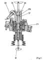
- Figure 2 shows compared to Figure 1 greatly enlarged the suction pad 6 as a single part.
- This has a holder 12 which is to be screwed to the carrier 3 shown in Figure 1.
- a ball head 13 is held adjustable and clamped in different angular positions.
- the ball head 13 has a through hole 14 in which two guide bodies 15, 15a screwed together are inserted from above.
- the upper guide body 15a is seated with a shoulder 16 on the ball head 13.
- the shaft 17 of the stopper 18 is to be clamped in the respective position relative to the guide body 15a by means of a pneumatic clamping device 21 arranged in the upper guide body 15a.
- the clamping device 21 has opposite each one actuating cylinder 22 with an actuating piston 23 which is able to press a clamping body 24 against the shaft 17.
- the shaft 17 has an external thread 25 in the clamping area, while the clamping body 24 is provided with an internal thread 26.
- FIG. 2 furthermore shows that the shaft 17 and the stop 18 are arranged coaxially with the absorbent body 9, which is a bellows in this embodiment.
- FIG. 3 shows that the clamping device 21 has two actuating pistons 23, 23a opposite one another. Accordingly, the clamping body 24 consists of two threaded nut halves 27, 28th
- the absorbent body 7 is designed as a suction plate and, in contrast to the previously described embodiment, is not fastened to the guide body 15 but to the shaft 17.
- a gas spring was provided instead of the spring 19 shown in Figure 2.
- the shaft 17 is connected to a piston 29 which limits a cylinder space 30 in the extension direction of the stopper 18.
- the cylinder chamber 30 is provided with a compressed air connection 31 so that it can be pressurized with more or less high pressure.
- Such an embodiment enables a novel assembly process.
Claims (11)
- Dispositif de préhension (2) configuré afin de saisir des objets (10), par exemple des vitres de véhicule ou des éléments de carrosserie à l'aide d'un bras de robot (1), qui comporte un support (3) avec au moins une pince aspirante, qui présente un corps aspirant (7, 8, 9) en forme de tasse, élastique, pouvant être posé sur l'objet à saisir (10), et sur lequel on peut exercer une dépression, et un butoir (18) définissant la position de l'objet saisi (10), moyennant quoi le butoir (18) est disposé de manière mobile dans la direction de préhension par rapport au support (3), et un dispositif de serrage (21) pouvant être actionné de manière motorisée afin de fixer le butoir (18) après une course définie à l'encontre du sens de préhension, caractérisé en ce que le butoir (18) est disposé respectivement à l'intérieur du corps aspirant (9) et est entouré par le corps aspirant (9), et en ce que le dispositif de préhension (2) comporte plusieurs pinces aspirantes (4, 5, 6) du type de la au moins une pince aspirante.
- Préhenseur selon la revendication 1, caractérisé en ce que le butoir (18) est précontraint par un ressort (19) dans la direction de préhension.
- Préhenseur selon la revendication 2, caractérisé en ce que le butoir (18) présente une tige (17) guidée de manière mobile axialement et reliée à un piston, et le piston délimite un espace cylindrique faisant office de ressort pneumatique, pouvant être sollicité par la pression, dans la direction de déploiement du butoir (18).
- Préhenseur selon au moins l'une quelconque des revendications précédentes, caractérisé en ce que le dispositif de serrage (21) présente un corps de serrage (24) pouvant être déplacé par un piston d'actionnement (23) pouvant être sollicité par des moyens de pression, dans la position de serrage, contre une tige (17) guidée de manière mobile axialement du butoir (18).
- Préhenseur selon la revendication 4, caractérisé en ce que la tige (17), dans la zone du corps de serrage (24), est dotée d'un filetage externe (25) et le corps de serrage (24) est constitué de deux moitiés d'écrou fileté (27, 28), et en ce que le dispositif de serrage (21) comporte deux pistons d'actionnement (23, 23a), qui sont respectivement prévus afin de déplacer une moitié d'écrou fileté (27, 28).
- Préhenseur selon au moins l'une quelconque des revendications précédentes, caractérisé en ce que le butoir (18) est maintenu dans un corps de guidage (15), qui est pour sa part inséré de manière amovible dans un alésage (14) d'une tête sphérique (13) maintenue de manière à pouvoir être réglée.
- Préhenseur selon la revendication 6, caractérisé en ce que le corps de guidage (15a) repose avec un épaulement (16) par le dessus sur la tête sphérique (13) et est relié de manière amovible à celle-ci.
- Préhenseur selon au moins l'une quelconque des revendications précédentes, caractérisé en ce que la tige (17) du butoir (18) fait saillie par rapport au corps de guidage (15a) au niveau du côté opposé au corps aspirant (9) et, au niveau du corps de guidage (15a) est disposé un capteur de position (20) surveillant la position de l'élément en saillie de la tige (17).
- Préhenseur selon au moins l'une quelconque des revendications précédentes, caractérisé en ce que le corps aspirant (9) est configuré sous la forme d'un soufflet et est fixé sur le corps de guidage (15).
- Préhenseur selon au moins l'une quelconque des revendications précédentes, caractérisé en ce que le corps aspirant (7) est configuré sous la forme d'une plaque de succion et est fixé sur la tige (17) du butoir (18).
- Procédé permettant de saisir et de monter des objets (10), par exemple, des vitres de véhicule ou des éléments de carrosserie à l'aide d'un dispositif de préhension (2) sur un bras de robot, qui comporte un support (3) avec plusieurs pinces aspirantes (4, 5, 6), qui présentent respectivement un corps aspirant (7, 8, 9) de type tasse, élastique, pouvant être posé sur l'objet à saisir (10), sur lequel on peut exercer une dépression, et un butoir (18) fixant la position de l'objet saisi (10), moyennant quoi on utilise des butoirs (18) pouvant être déplacés dans la direction de préhension grâce à un milieu sous pression, caractérisé en ce que les butoirs, pour recevoir l'objet (10) respectif, sont tout d'abord déployés complètement avec une pression élevée puis, lors de la réception, on exerce sur eux une pression plus faible de telle sorte qu'un déplacement des butoirs (18) correspondant au contour de l'objet est possible, et en ce que, lors de l'insertion de l'objet (10), celui-ci peut être déplacé grâce à l'exercice d'une pression sur les butoirs (18) dans la position de montage finale, et en ce que les butoirs (18), après avoir été adaptés au contour de l'objet (10) respectif, sont fixés grâce à un dispositif de serrage (21) pouvant être actionné par voie motorisée dans leur position axiale respective.
Applications Claiming Priority (2)
| Application Number | Priority Date | Filing Date | Title |
|---|---|---|---|
| DE10121344A DE10121344A1 (de) | 2001-05-02 | 2001-05-02 | Zum Greifen von Gegenständen ausgebildete Greifvorrichtung |
| DE10121344 | 2001-05-02 |
Publications (2)
| Publication Number | Publication Date |
|---|---|
| EP1256421A1 EP1256421A1 (fr) | 2002-11-13 |
| EP1256421B1 true EP1256421B1 (fr) | 2008-01-23 |
Family
ID=7683373
Family Applications (1)
| Application Number | Title | Priority Date | Filing Date |
|---|---|---|---|
| EP02009105A Expired - Lifetime EP1256421B1 (fr) | 2001-05-02 | 2002-04-24 | Tête de préhension par aspiration équipée de butées réglables |
Country Status (4)
| Country | Link |
|---|---|
| EP (1) | EP1256421B1 (fr) |
| AT (1) | ATE384602T1 (fr) |
| DE (3) | DE10121344A1 (fr) |
| ES (1) | ES2300397T3 (fr) |
Cited By (13)
| Publication number | Priority date | Publication date | Assignee | Title |
|---|---|---|---|---|
| EP2495292A1 (fr) | 2011-03-04 | 2012-09-05 | FFT EDAG Produktionssysteme GmbH & Co. KG | Dispositif de prétraitement de surfaces d'assemblage et procédé de prétraitement de surfaces d'assemblage |
| EP2762267A2 (fr) | 2013-02-04 | 2014-08-06 | J. Schmalz GmbH | Dispositif de serrage |
| EP2824526A2 (fr) | 2008-05-21 | 2015-01-14 | FFT EDAG Produktionssysteme GmbH & Co. KG | Jointoiement de composants sans cadre de serrage |
| US10011020B2 (en) | 2016-01-08 | 2018-07-03 | Berkshire Grey, Inc. | Systems and methods for acquiring and moving objects |
| US10118300B2 (en) | 2015-09-08 | 2018-11-06 | Berkshire Grey, Inc. | Systems and methods for providing high flow vacuum acquisition in automated systems |
| US10265872B2 (en) | 2015-09-09 | 2019-04-23 | Berkshire Grey, Inc. | Systems and methods for providing dynamic communicative lighting in a robotic environment |
| US10618177B2 (en) | 2015-08-26 | 2020-04-14 | Berkshire Grey, Inc. | Systems and methods for providing contact detection in an articulated arm |
| US10639787B2 (en) | 2017-03-06 | 2020-05-05 | Berkshire Grey, Inc. | Systems and methods for efficiently moving a variety of objects |
| US10647005B2 (en) | 2015-08-26 | 2020-05-12 | Berkshire Grey, Inc. | System and methods for providing vacuum valve assemblies for end effectors |
| US10647002B2 (en) | 2015-09-01 | 2020-05-12 | Berkshire Grey, Inc. | Systems and methods for providing dynamic robotic control systems |
| US10723019B2 (en) | 2017-08-02 | 2020-07-28 | Berkshire Grey, Inc. | Systems and methods for acquiring and moving objects having complex outer surfaces |
| US11938618B2 (en) | 2020-07-22 | 2024-03-26 | Berkshire Grey Operating Company, Inc. | Systems and methods for object processing using a passively folding vacuum gripper |
| US11964386B2 (en) | 2020-07-22 | 2024-04-23 | Berkshire Grey Operating Company, Inc. | Systems and methods for object processing using a vacuum gripper that provides object retention by shroud inversion |
Families Citing this family (34)
| Publication number | Priority date | Publication date | Assignee | Title |
|---|---|---|---|---|
| DE10227874B4 (de) * | 2002-06-22 | 2006-03-23 | Bayerische Motoren Werke Ag | Vakuumgreifer |
| EP1396313A1 (fr) | 2002-09-03 | 2004-03-10 | Nissan Motor Co., Ltd. | Main tout usage munie de ventouses de préhension pour un manipulateur multiaxe |
| DE10303844A1 (de) * | 2003-01-30 | 2005-05-19 | Daimlerchrysler Ag | Montagewerkzeug und geeignete Handhabungseinrichtung |
| FR2888522A1 (fr) * | 2005-07-12 | 2007-01-19 | Renault Sas | Dispositif de prehension de tole comportant un dispositif de controle de la presence d'ecrou |
| DE102005033540A1 (de) * | 2005-07-14 | 2007-01-18 | Fft Flexible Fertigungstechnik Gmbh & Co Kg | Zum Greifen von Gegenständen ausgebildete Greifvorrichtung und Verfahren zum Greifen und Montieren von Gegenständen |
| DE102005062706A1 (de) * | 2005-12-24 | 2007-07-05 | Universität Dortmund | Vorrichtung zum direkt-kraftschlüssigen Greifen von geometrievarianten Gegenständen mit Robotern und Handhabungseinrichtungen |
| DE102008036501B4 (de) | 2008-08-05 | 2015-01-15 | Dürr Somac GmbH | Verfahren zum Betrieb eines Robotergreifers und Robotergreifer |
| DE102009010694A1 (de) * | 2009-02-26 | 2010-09-02 | Audi Ag | Greiferanordnung, Greifer und Verfahren zum Aufnehmen eines Gegenstands |
| DE102009015361A1 (de) | 2009-03-27 | 2009-10-29 | Daimler Ag | Greifvorrichtung und Verfahren zum Greifen eines Bauteils |
| AT511558B1 (de) * | 2011-05-30 | 2013-04-15 | Knapp Ag | Knickarmgreifer |
| DE102012224280A1 (de) * | 2012-12-21 | 2014-06-26 | J. Schmalz Gmbh | Spannvorrichtung |
| DE102013016820B4 (de) | 2013-10-10 | 2017-10-19 | Daimler Ag | Handhabungssystem für unterschiedliche Bauteilvarianten und Verfahren zum Betreiben eines Handhabungssystems |
| DE102014005793A1 (de) * | 2014-04-19 | 2015-10-22 | Daimler Ag | Handhabungseinrichtung sowie Verfahren zum Verbinden eines ersten Bauteils mit einem zweiten Bauteil, insbesondere für einen Kraftwagen |
| CN104070481B (zh) * | 2014-06-23 | 2016-03-30 | 苏州爱德蒙得测控系统有限公司 | 浮动定位及保护机构 |
| CN104308776B (zh) * | 2014-10-21 | 2016-03-23 | 西安煤矿机械有限公司 | 采矿设备终端执行机构齿座安装用工装 |
| US11370128B2 (en) | 2015-09-01 | 2022-06-28 | Berkshire Grey Operating Company, Inc. | Systems and methods for providing dynamic robotic control systems |
| CN105314398B (zh) * | 2015-11-06 | 2017-11-28 | 重庆长安汽车股份有限公司 | 多车型柔性顶盖抓具 |
| CA3107257C (fr) | 2015-11-13 | 2023-05-02 | Berkshire Grey, Inc. | Systemes de tri et procedes pour assurer le tri de divers objets |
| WO2017139330A1 (fr) | 2016-02-08 | 2017-08-17 | Berkshire Grey Inc. | Systèmes et procédés de réalisation du traitement de divers objets en utilisant la planification de mouvements |
| DE202017103238U1 (de) | 2017-05-30 | 2017-06-27 | Fipa Holding Gmbh | Sauggreifer zum Handhaben von Gegenständen |
| CN107159528B (zh) * | 2017-07-19 | 2023-07-07 | 江西迪迪工业智能设备有限公司 | 一种点胶机旋转夹紧装置及其操作方法 |
| US10814498B2 (en) | 2017-11-07 | 2020-10-27 | Berkshire Grey, Inc. | Systems and methods for providing dynamic vacuum pressure at an end effector using a single vacuum source |
| DE102018002613A1 (de) | 2018-03-29 | 2019-10-02 | Psa Automobiles Sa | Befestigungsanordnung, Handhabungsvorrichtung mit der Befestigungsanordnung und Auflagevorrichtung mit der Handhabungsvorrichtung |
| EP3578323B1 (fr) * | 2018-06-05 | 2020-08-12 | C.R.F. Società Consortile per Azioni | Dispositif de préhension de type aspirant |
| EP3829827A1 (fr) | 2018-07-27 | 2021-06-09 | Berkshire Grey, Inc. | Systèmes et procédés pour échanger efficacement des outils d'effecteur d'extrémité |
| CN111824875B (zh) * | 2019-04-16 | 2023-02-21 | 富士达株式会社 | 电梯用调速装置的缆索夹入机构 |
| CN110790006B (zh) * | 2019-05-14 | 2021-01-19 | 延安大学 | 一种机械制造抓取装置及其使用方法 |
| CA3150291A1 (fr) | 2019-08-08 | 2021-02-11 | Berkshire Grey, Inc. | Systemes et procedes pour fournir, dans des dispositifs de mouvement programmables, des effecteurs terminaux conformes avec attenuation du bruit |
| US20210129351A1 (en) * | 2019-11-05 | 2021-05-06 | Nissan North America, Inc. | End Effectors for Robotic Units Used to Open and Close Vehicle Doors |
| DE102020105733A1 (de) | 2020-03-04 | 2021-09-09 | Bayerische Motoren Werke Aktiengesellschaft | Greifelement für eine Vakuumgreifeinrichtung sowie Vakuumgreifeinrichtung |
| CN111217144A (zh) * | 2020-03-25 | 2020-06-02 | 深圳市拓野机器人自动化有限公司 | 一种对针座自动定位的吸附式末端执行器及其使用方法 |
| CN111573272B (zh) * | 2020-05-13 | 2021-11-19 | 盐城市钊扬工业设计有限公司 | 一种机床生产用运输装置 |
| CN113414723B (zh) * | 2021-06-10 | 2022-09-02 | 江苏威马悦达智能装备有限公司 | 一种快换式连杆加工固定工装 |
| DE202023101336U1 (de) | 2023-03-17 | 2023-03-23 | Fipa Holding Gmbh | Haltevorrichtung für ein pneumatisch arbeitendes Greifelement |
Citations (2)
| Publication number | Priority date | Publication date | Assignee | Title |
|---|---|---|---|---|
| JPH0538693A (ja) * | 1991-08-06 | 1993-02-19 | Fanuc Ltd | 吸着式ハンド |
| JPH07291440A (ja) * | 1994-04-22 | 1995-11-07 | Toshiba Corp | 搬送装置 |
Family Cites Families (6)
| Publication number | Priority date | Publication date | Assignee | Title |
|---|---|---|---|---|
| JPH06336392A (ja) * | 1993-05-25 | 1994-12-06 | Toshiba Corp | ハンド |
| US5433492A (en) * | 1994-03-01 | 1995-07-18 | Tdw Delaware, Inc. | Ferrous chip removal tool |
| FR2724644B1 (fr) * | 1994-09-16 | 1996-12-27 | Renault | Ventouses de prehension et dispositif de prehension les comportant |
| DE4442137C2 (de) * | 1994-11-26 | 1997-04-03 | Herbert Gegenheimer | Modular erweiterbare, dreidimensional verstellbare Vorrichtung mit Greifern |
| DE19817777C1 (de) * | 1998-04-21 | 1999-09-09 | Schmalz J Gmbh | Unterdruckhandhabungseinrichtung |
| FR2793434B1 (fr) * | 1999-05-12 | 2001-06-08 | Renault Automation | Outil a configuration variable pour le maintien de flans |
-
2001
- 2001-05-02 DE DE10121344A patent/DE10121344A1/de not_active Withdrawn
-
2002
- 2002-04-24 EP EP02009105A patent/EP1256421B1/fr not_active Expired - Lifetime
- 2002-04-24 AT AT02009105T patent/ATE384602T1/de active
- 2002-04-24 ES ES02009105T patent/ES2300397T3/es not_active Expired - Lifetime
- 2002-04-24 DE DE50211585T patent/DE50211585D1/de not_active Expired - Lifetime
- 2002-04-24 DE DE20221729U patent/DE20221729U1/de not_active Expired - Lifetime
Patent Citations (2)
| Publication number | Priority date | Publication date | Assignee | Title |
|---|---|---|---|---|
| JPH0538693A (ja) * | 1991-08-06 | 1993-02-19 | Fanuc Ltd | 吸着式ハンド |
| JPH07291440A (ja) * | 1994-04-22 | 1995-11-07 | Toshiba Corp | 搬送装置 |
Non-Patent Citations (2)
| Title |
|---|
| PATENT ABSTRACTS OF JAPAN vol. 017, no. 324 (M - 1433) 21 June 1993 (1993-06-21) * |
| PATENT ABSTRACTS OF JAPAN vol. 1996, no. 03 29 March 1996 (1996-03-29) * |
Cited By (37)
| Publication number | Priority date | Publication date | Assignee | Title |
|---|---|---|---|---|
| EP2824526A2 (fr) | 2008-05-21 | 2015-01-14 | FFT EDAG Produktionssysteme GmbH & Co. KG | Jointoiement de composants sans cadre de serrage |
| EP2495292A1 (fr) | 2011-03-04 | 2012-09-05 | FFT EDAG Produktionssysteme GmbH & Co. KG | Dispositif de prétraitement de surfaces d'assemblage et procédé de prétraitement de surfaces d'assemblage |
| DE102013201765B4 (de) | 2013-02-04 | 2019-02-07 | J. Schmalz Gmbh | Spannvorrichtung mit Hubzylindern |
| EP2762267A2 (fr) | 2013-02-04 | 2014-08-06 | J. Schmalz GmbH | Dispositif de serrage |
| DE102013201765A1 (de) | 2013-02-04 | 2014-08-07 | J. Schmalz Gmbh | Spannvorrichtung |
| EP2762267A3 (fr) * | 2013-02-04 | 2015-12-23 | J. Schmalz GmbH | Dispositif de serrage |
| US11597095B2 (en) | 2015-08-26 | 2023-03-07 | Berkshire Grey Operating Company, Inc. | Systems and methods for providing contact detection in an articulated arm |
| US11660763B2 (en) | 2015-08-26 | 2023-05-30 | Berkshire Grey Operating Company, Inc. | Systems and methods for providing vacuum valve assemblies for end effectors |
| US11813734B2 (en) | 2015-08-26 | 2023-11-14 | Berkshire Grey Operating Company, Inc. | Systems and methods for providing contact detection in an articulated arm |
| US11370122B2 (en) | 2015-08-26 | 2022-06-28 | Berkshire Grey Operating Company, Inc. | Systems and methods for providing contact detection in an articulated arm |
| US11185996B2 (en) | 2015-08-26 | 2021-11-30 | Berkshire Grey, Inc. | Systems and methods for providing vacuum valve assemblies for end effectors |
| US10618177B2 (en) | 2015-08-26 | 2020-04-14 | Berkshire Grey, Inc. | Systems and methods for providing contact detection in an articulated arm |
| US10913159B2 (en) | 2015-08-26 | 2021-02-09 | Berkshire Grey, Inc. | Systems and methods for providing contact detection in an articulated arm |
| US10875185B2 (en) | 2015-08-26 | 2020-12-29 | Berkshire Grey, Inc. | Systems and methods for providing contact detection in an articulated arm |
| US10647005B2 (en) | 2015-08-26 | 2020-05-12 | Berkshire Grey, Inc. | System and methods for providing vacuum valve assemblies for end effectors |
| US10647002B2 (en) | 2015-09-01 | 2020-05-12 | Berkshire Grey, Inc. | Systems and methods for providing dynamic robotic control systems |
| US10315315B2 (en) | 2015-09-08 | 2019-06-11 | Berkshire Grey, Inc. | Systems and methods for providing dynamic vacuum pressure in an articulated arm end effector |
| US10576641B2 (en) | 2015-09-08 | 2020-03-03 | Berkshire Grey, Inc. | Systems and methods for providing high flow vacuum acquisition in automated systems |
| US10857682B2 (en) | 2015-09-08 | 2020-12-08 | Berkshire Grey, Inc. | Systems and methods for providing high flow vacuum acquisition in automated systems |
| US11945100B2 (en) | 2015-09-08 | 2024-04-02 | Berkshire Grey Operating Company, Inc. | Systems and methods for providing high flow vacuum acquisition in automated systems |
| US10118300B2 (en) | 2015-09-08 | 2018-11-06 | Berkshire Grey, Inc. | Systems and methods for providing high flow vacuum acquisition in automated systems |
| US10596711B2 (en) | 2015-09-08 | 2020-03-24 | Berkshire Grey, Inc. | Systems and methods for providing dynamic vacuum pressure in an articulated arm end effector |
| US11198224B2 (en) | 2015-09-08 | 2021-12-14 | Berkshire Grey, Inc. | Systems and methods for providing dynamic vacuum pressure in an articulated arm end effector |
| US10265872B2 (en) | 2015-09-09 | 2019-04-23 | Berkshire Grey, Inc. | Systems and methods for providing dynamic communicative lighting in a robotic environment |
| US10632631B2 (en) | 2015-09-09 | 2020-04-28 | Berkshire Grey, Inc. | Systems and methods for providing dynamic communicative lighting in a robotic environment |
| US11865699B2 (en) | 2016-01-08 | 2024-01-09 | Berkshire Grey Operating Company, Inc. | Systems and methods for acquiring and moving objects |
| US11370127B2 (en) | 2016-01-08 | 2022-06-28 | Berkshire Grey Operating Company, Inc. | Systems and methods for acquiring and moving objects |
| US11318623B2 (en) | 2016-01-08 | 2022-05-03 | Berkshire Grey Operating Company, Inc. | Systems and methods for acquiring and moving objects |
| US10011020B2 (en) | 2016-01-08 | 2018-07-03 | Berkshire Grey, Inc. | Systems and methods for acquiring and moving objects |
| US11203115B2 (en) | 2017-03-06 | 2021-12-21 | Berkshire Grey, Inc. | Systems and methods for efficiently moving a variety of objects |
| US10639787B2 (en) | 2017-03-06 | 2020-05-05 | Berkshire Grey, Inc. | Systems and methods for efficiently moving a variety of objects |
| US11839974B2 (en) | 2017-03-06 | 2023-12-12 | Berkshire Grey Operating Company, Inc. | Systems and methods for efficiently moving a variety of objects |
| US10723019B2 (en) | 2017-08-02 | 2020-07-28 | Berkshire Grey, Inc. | Systems and methods for acquiring and moving objects having complex outer surfaces |
| US11724389B2 (en) | 2017-08-02 | 2023-08-15 | Berkshire Grey Operating Company, Inc. | Systems and methods for acquiring and moving objects having complex outer surfaces |
| US11938618B2 (en) | 2020-07-22 | 2024-03-26 | Berkshire Grey Operating Company, Inc. | Systems and methods for object processing using a passively folding vacuum gripper |
| US11945103B2 (en) | 2020-07-22 | 2024-04-02 | Berkshire Grey Operating Company, Inc. | Systems and methods for object processing using a passively collapsing vacuum gripper |
| US11964386B2 (en) | 2020-07-22 | 2024-04-23 | Berkshire Grey Operating Company, Inc. | Systems and methods for object processing using a vacuum gripper that provides object retention by shroud inversion |
Also Published As
| Publication number | Publication date |
|---|---|
| DE50211585D1 (de) | 2008-03-13 |
| ES2300397T3 (es) | 2008-06-16 |
| DE10121344A1 (de) | 2002-11-07 |
| EP1256421A1 (fr) | 2002-11-13 |
| ATE384602T1 (de) | 2008-02-15 |
| DE20221729U1 (de) | 2007-04-26 |
Similar Documents
| Publication | Publication Date | Title |
|---|---|---|
| EP1256421B1 (fr) | Tête de préhension par aspiration équipée de butées réglables | |
| DE3133205C2 (de) | Aufeinanderfolgend klemmende und lösende Greifvorrichtung | |
| EP2089899B1 (fr) | Dispositif pour le positionnement et/ou l'application par pression d'un composant plat par rapport à un substrat et procédé pour le positionnement d'un outil de fixation par rapport à un substrat | |
| EP1674197B1 (fr) | Dispositif d'alimentation des panneaux | |
| DE19962421C1 (de) | Verfahren und Vorrichtung zum Kuppeln/Entkuppeln eines Zylinders in einer Druckmaschine | |
| EP1110612B1 (fr) | Système de pipetage avec pipette et embout-seringue | |
| WO2018219835A1 (fr) | Dispositif pour la rotation de pièces et son utilisation | |
| CH619629A5 (fr) | ||
| DE10135280A1 (de) | Spannelement zum positionsflexiblen Spannen von Werkstücken | |
| DE102017212660A1 (de) | Saugvorrichtung | |
| DE102008036501A1 (de) | Verfahren zum Betrieb eines Robotergreifers und Robotergreifer | |
| WO2010118734A1 (fr) | Dispositif de saisie intérieure de corps creux | |
| EP2745987A2 (fr) | Dispositif de serrage | |
| DE102007004186B4 (de) | Radmontage-Industrieroboter und Verfahren zum Betrieb eines Radmontage-Industrieroboters | |
| EP0458830B1 (fr) | Tete de montage de manipulateurs | |
| DE102005033540A1 (de) | Zum Greifen von Gegenständen ausgebildete Greifvorrichtung und Verfahren zum Greifen und Montieren von Gegenständen | |
| EP2285510B1 (fr) | PRESSE COMPRENANT UN DISPOSITIF DE TRANSFERT POUR avancer LES PIÈCES PAS À PAS ET avec UN dispositif d' ACCOUPLEMENT des barres de préhension | |
| EP2590778B1 (fr) | Dispositif de support universel pour le support d'une piece | |
| EP2829339B1 (fr) | Dispositif de positionnement pour pièces à usiner, machine-outil dotée d'un tel dispositif de positionnement, procédé de positionnement de pièces à usiner | |
| DE102006009432B4 (de) | Greifvorrichtung für eine Werkzeugwechselvorrichtung | |
| DE102019112125A1 (de) | Greifervorrichtung | |
| DE102019003755A1 (de) | Verfahren und System zum Fügen eines zweiten Bauteils an ein erstes Bauvteil | |
| EP3378608A1 (fr) | Dispositif de manipulation et procédé de fonctionnement d'un tel dispositif | |
| DE3822377C2 (fr) | ||
| DE102018008144B4 (de) | Spannfutter zum Einspannen eines Werkstücks oder Werkzeugs |
Legal Events
| Date | Code | Title | Description |
|---|---|---|---|
| PUAI | Public reference made under article 153(3) epc to a published international application that has entered the european phase |
Free format text: ORIGINAL CODE: 0009012 |
|
| AK | Designated contracting states |
Kind code of ref document: A1 Designated state(s): AT BE CH CY DE DK ES FI FR GB GR IE IT LI LU MC NL PT SE TR |
|
| AX | Request for extension of the european patent |
Free format text: AL;LT;LV;MK;RO;SI |
|
| 17P | Request for examination filed |
Effective date: 20030510 |
|
| AKX | Designation fees paid |
Designated state(s): AT BE CH CY DE DK ES FI FR GB GR IE IT LI LU MC NL PT SE TR |
|
| GRAP | Despatch of communication of intention to grant a patent |
Free format text: ORIGINAL CODE: EPIDOSNIGR1 |
|
| GRAS | Grant fee paid |
Free format text: ORIGINAL CODE: EPIDOSNIGR3 |
|
| GRAA | (expected) grant |
Free format text: ORIGINAL CODE: 0009210 |
|
| AK | Designated contracting states |
Kind code of ref document: B1 Designated state(s): AT BE CH CY DE DK ES FI FR GB GR IE IT LI LU MC NL PT SE TR |
|
| REG | Reference to a national code |
Ref country code: GB Ref legal event code: FG4D Free format text: NOT ENGLISH |
|
| REG | Reference to a national code |
Ref country code: CH Ref legal event code: EP |
|
| REG | Reference to a national code |
Ref country code: IE Ref legal event code: FG4D Free format text: LANGUAGE OF EP DOCUMENT: GERMAN |
|
| REF | Corresponds to: |
Ref document number: 50211585 Country of ref document: DE Date of ref document: 20080313 Kind code of ref document: P |
|
| GBT | Gb: translation of ep patent filed (gb section 77(6)(a)/1977) |
Effective date: 20080420 |
|
| REG | Reference to a national code |
Ref country code: ES Ref legal event code: FG2A Ref document number: 2300397 Country of ref document: ES Kind code of ref document: T3 |
|
| NLV1 | Nl: lapsed or annulled due to failure to fulfill the requirements of art. 29p and 29m of the patents act | ||
| PG25 | Lapsed in a contracting state [announced via postgrant information from national office to epo] |
Ref country code: FI Free format text: LAPSE BECAUSE OF FAILURE TO SUBMIT A TRANSLATION OF THE DESCRIPTION OR TO PAY THE FEE WITHIN THE PRESCRIBED TIME-LIMIT Effective date: 20080123 |
|
| PG25 | Lapsed in a contracting state [announced via postgrant information from national office to epo] |
Ref country code: PT Free format text: LAPSE BECAUSE OF FAILURE TO SUBMIT A TRANSLATION OF THE DESCRIPTION OR TO PAY THE FEE WITHIN THE PRESCRIBED TIME-LIMIT Effective date: 20080623 |
|
| REG | Reference to a national code |
Ref country code: IE Ref legal event code: FD4D |
|
| ET | Fr: translation filed | ||
| PG25 | Lapsed in a contracting state [announced via postgrant information from national office to epo] |
Ref country code: NL Free format text: LAPSE BECAUSE OF FAILURE TO SUBMIT A TRANSLATION OF THE DESCRIPTION OR TO PAY THE FEE WITHIN THE PRESCRIBED TIME-LIMIT Effective date: 20080123 Ref country code: IE Free format text: LAPSE BECAUSE OF FAILURE TO SUBMIT A TRANSLATION OF THE DESCRIPTION OR TO PAY THE FEE WITHIN THE PRESCRIBED TIME-LIMIT Effective date: 20080123 Ref country code: SE Free format text: LAPSE BECAUSE OF FAILURE TO SUBMIT A TRANSLATION OF THE DESCRIPTION OR TO PAY THE FEE WITHIN THE PRESCRIBED TIME-LIMIT Effective date: 20080423 Ref country code: DK Free format text: LAPSE BECAUSE OF FAILURE TO SUBMIT A TRANSLATION OF THE DESCRIPTION OR TO PAY THE FEE WITHIN THE PRESCRIBED TIME-LIMIT Effective date: 20080123 |
|
| PG25 | Lapsed in a contracting state [announced via postgrant information from national office to epo] |
Ref country code: MC Free format text: LAPSE BECAUSE OF NON-PAYMENT OF DUE FEES Effective date: 20080430 |
|
| PLBE | No opposition filed within time limit |
Free format text: ORIGINAL CODE: 0009261 |
|
| REG | Reference to a national code |
Ref country code: CH Ref legal event code: PL |
|
| STAA | Information on the status of an ep patent application or granted ep patent |
Free format text: STATUS: NO OPPOSITION FILED WITHIN TIME LIMIT |
|
| 26N | No opposition filed |
Effective date: 20081024 |
|
| PG25 | Lapsed in a contracting state [announced via postgrant information from national office to epo] |
Ref country code: LI Free format text: LAPSE BECAUSE OF NON-PAYMENT OF DUE FEES Effective date: 20080430 Ref country code: CH Free format text: LAPSE BECAUSE OF NON-PAYMENT OF DUE FEES Effective date: 20080430 |
|
| PG25 | Lapsed in a contracting state [announced via postgrant information from national office to epo] |
Ref country code: CY Free format text: LAPSE BECAUSE OF FAILURE TO SUBMIT A TRANSLATION OF THE DESCRIPTION OR TO PAY THE FEE WITHIN THE PRESCRIBED TIME-LIMIT Effective date: 20080123 |
|
| PG25 | Lapsed in a contracting state [announced via postgrant information from national office to epo] |
Ref country code: IT Free format text: LAPSE BECAUSE OF FAILURE TO SUBMIT A TRANSLATION OF THE DESCRIPTION OR TO PAY THE FEE WITHIN THE PRESCRIBED TIME-LIMIT Effective date: 20080123 |
|
| PG25 | Lapsed in a contracting state [announced via postgrant information from national office to epo] |
Ref country code: LU Free format text: LAPSE BECAUSE OF NON-PAYMENT OF DUE FEES Effective date: 20080424 |
|
| PG25 | Lapsed in a contracting state [announced via postgrant information from national office to epo] |
Ref country code: TR Free format text: LAPSE BECAUSE OF FAILURE TO SUBMIT A TRANSLATION OF THE DESCRIPTION OR TO PAY THE FEE WITHIN THE PRESCRIBED TIME-LIMIT Effective date: 20080123 |
|
| PG25 | Lapsed in a contracting state [announced via postgrant information from national office to epo] |
Ref country code: GR Free format text: LAPSE BECAUSE OF FAILURE TO SUBMIT A TRANSLATION OF THE DESCRIPTION OR TO PAY THE FEE WITHIN THE PRESCRIBED TIME-LIMIT Effective date: 20080424 |
|
| REG | Reference to a national code |
Ref country code: FR Ref legal event code: TP Owner name: FFT EDAG PRODUKTIONSSYSTEME GMBH & CO. KG, DE Effective date: 20120531 |
|
| REG | Reference to a national code |
Ref country code: DE Ref legal event code: R082 Ref document number: 50211585 Country of ref document: DE Representative=s name: SCHWABE SANDMAIR MARX, DE |
|
| REG | Reference to a national code |
Ref country code: DE Ref legal event code: R082 Ref document number: 50211585 Country of ref document: DE Representative=s name: SCHWABE SANDMAIR MARX, DE Effective date: 20120713 Ref country code: DE Ref legal event code: R081 Ref document number: 50211585 Country of ref document: DE Owner name: FFT EDAG PRODUKTIONSSYSTEME GMBH & CO. KG, DE Free format text: FORMER OWNER: EDAG GMBH & CO. KGAA, 36039 FULDA, DE Effective date: 20120713 Ref country code: DE Ref legal event code: R082 Ref document number: 50211585 Country of ref document: DE Representative=s name: SCHWABE SANDMAIR MARX PATENTANWAELTE RECHTSANW, DE Effective date: 20120713 |
|
| REG | Reference to a national code |
Ref country code: AT Ref legal event code: PC Ref document number: 384602 Country of ref document: AT Kind code of ref document: T Owner name: FFT EDAG PRODUKTIONSSYSTEME GMBH & CO. KG, DE Effective date: 20120920 |
|
| REG | Reference to a national code |
Ref country code: FR Ref legal event code: PLFP Year of fee payment: 15 |
|
| REG | Reference to a national code |
Ref country code: FR Ref legal event code: PLFP Year of fee payment: 16 |
|
| REG | Reference to a national code |
Ref country code: FR Ref legal event code: PLFP Year of fee payment: 17 |
|
| PGFP | Annual fee paid to national office [announced via postgrant information from national office to epo] |
Ref country code: DE Payment date: 20210421 Year of fee payment: 20 Ref country code: FR Payment date: 20210421 Year of fee payment: 20 |
|
| PGFP | Annual fee paid to national office [announced via postgrant information from national office to epo] |
Ref country code: GB Payment date: 20210422 Year of fee payment: 20 Ref country code: ES Payment date: 20210519 Year of fee payment: 20 Ref country code: AT Payment date: 20210420 Year of fee payment: 20 Ref country code: BE Payment date: 20210421 Year of fee payment: 20 |
|
| REG | Reference to a national code |
Ref country code: DE Ref legal event code: R071 Ref document number: 50211585 Country of ref document: DE |
|
| REG | Reference to a national code |
Ref country code: BE Ref legal event code: MK Effective date: 20220424 |
|
| REG | Reference to a national code |
Ref country code: GB Ref legal event code: PE20 Expiry date: 20220423 |
|
| REG | Reference to a national code |
Ref country code: AT Ref legal event code: MK07 Ref document number: 384602 Country of ref document: AT Kind code of ref document: T Effective date: 20220424 |
|
| PG25 | Lapsed in a contracting state [announced via postgrant information from national office to epo] |
Ref country code: GB Free format text: LAPSE BECAUSE OF EXPIRATION OF PROTECTION Effective date: 20220423 |
|
| REG | Reference to a national code |
Ref country code: ES Ref legal event code: FD2A Effective date: 20220803 |
|
| PG25 | Lapsed in a contracting state [announced via postgrant information from national office to epo] |
Ref country code: ES Free format text: LAPSE BECAUSE OF EXPIRATION OF PROTECTION Effective date: 20220425 |