EP1256378A2 - Vorrichtung und Verfahren zur paralellen Durchführung von Experimenten - Google Patents
Vorrichtung und Verfahren zur paralellen Durchführung von Experimenten Download PDFInfo
- Publication number
- EP1256378A2 EP1256378A2 EP02009277A EP02009277A EP1256378A2 EP 1256378 A2 EP1256378 A2 EP 1256378A2 EP 02009277 A EP02009277 A EP 02009277A EP 02009277 A EP02009277 A EP 02009277A EP 1256378 A2 EP1256378 A2 EP 1256378A2
- Authority
- EP
- European Patent Office
- Prior art keywords
- pressure
- individual
- individual reactors
- temperature
- reaction
- Prior art date
- Legal status (The legal status is an assumption and is not a legal conclusion. Google has not performed a legal analysis and makes no representation as to the accuracy of the status listed.)
- Withdrawn
Links
Images








Classifications
-
- B—PERFORMING OPERATIONS; TRANSPORTING
- B01—PHYSICAL OR CHEMICAL PROCESSES OR APPARATUS IN GENERAL
- B01L—CHEMICAL OR PHYSICAL LABORATORY APPARATUS FOR GENERAL USE
- B01L3/00—Containers or dishes for laboratory use, e.g. laboratory glassware; Droppers
- B01L3/50—Containers for the purpose of retaining a material to be analysed, e.g. test tubes
- B01L3/508—Rigid containers without fluid transport within
- B01L3/5085—Rigid containers without fluid transport within for multiple samples, e.g. microtitration plates
- B01L3/50851—Rigid containers without fluid transport within for multiple samples, e.g. microtitration plates specially adapted for heating or cooling samples
-
- B—PERFORMING OPERATIONS; TRANSPORTING
- B01—PHYSICAL OR CHEMICAL PROCESSES OR APPARATUS IN GENERAL
- B01J—CHEMICAL OR PHYSICAL PROCESSES, e.g. CATALYSIS OR COLLOID CHEMISTRY; THEIR RELEVANT APPARATUS
- B01J19/00—Chemical, physical or physico-chemical processes in general; Their relevant apparatus
- B01J19/0046—Sequential or parallel reactions, e.g. for the synthesis of polypeptides or polynucleotides; Apparatus and devices for combinatorial chemistry or for making molecular arrays
-
- B—PERFORMING OPERATIONS; TRANSPORTING
- B01—PHYSICAL OR CHEMICAL PROCESSES OR APPARATUS IN GENERAL
- B01L—CHEMICAL OR PHYSICAL LABORATORY APPARATUS FOR GENERAL USE
- B01L7/00—Heating or cooling apparatus; Heat insulating devices
-
- B—PERFORMING OPERATIONS; TRANSPORTING
- B01—PHYSICAL OR CHEMICAL PROCESSES OR APPARATUS IN GENERAL
- B01J—CHEMICAL OR PHYSICAL PROCESSES, e.g. CATALYSIS OR COLLOID CHEMISTRY; THEIR RELEVANT APPARATUS
- B01J2219/00—Chemical, physical or physico-chemical processes in general; Their relevant apparatus
- B01J2219/00274—Sequential or parallel reactions; Apparatus and devices for combinatorial chemistry or for making arrays; Chemical library technology
- B01J2219/00277—Apparatus
- B01J2219/00279—Features relating to reactor vessels
- B01J2219/00281—Individual reactor vessels
- B01J2219/00283—Reactor vessels with top opening
-
- B—PERFORMING OPERATIONS; TRANSPORTING
- B01—PHYSICAL OR CHEMICAL PROCESSES OR APPARATUS IN GENERAL
- B01J—CHEMICAL OR PHYSICAL PROCESSES, e.g. CATALYSIS OR COLLOID CHEMISTRY; THEIR RELEVANT APPARATUS
- B01J2219/00—Chemical, physical or physico-chemical processes in general; Their relevant apparatus
- B01J2219/00274—Sequential or parallel reactions; Apparatus and devices for combinatorial chemistry or for making arrays; Chemical library technology
- B01J2219/00277—Apparatus
- B01J2219/00351—Means for dispensing and evacuation of reagents
- B01J2219/00389—Feeding through valves
-
- B—PERFORMING OPERATIONS; TRANSPORTING
- B01—PHYSICAL OR CHEMICAL PROCESSES OR APPARATUS IN GENERAL
- B01J—CHEMICAL OR PHYSICAL PROCESSES, e.g. CATALYSIS OR COLLOID CHEMISTRY; THEIR RELEVANT APPARATUS
- B01J2219/00—Chemical, physical or physico-chemical processes in general; Their relevant apparatus
- B01J2219/00274—Sequential or parallel reactions; Apparatus and devices for combinatorial chemistry or for making arrays; Chemical library technology
- B01J2219/00277—Apparatus
- B01J2219/00351—Means for dispensing and evacuation of reagents
- B01J2219/00418—Means for dispensing and evacuation of reagents using pressure
-
- B—PERFORMING OPERATIONS; TRANSPORTING
- B01—PHYSICAL OR CHEMICAL PROCESSES OR APPARATUS IN GENERAL
- B01J—CHEMICAL OR PHYSICAL PROCESSES, e.g. CATALYSIS OR COLLOID CHEMISTRY; THEIR RELEVANT APPARATUS
- B01J2219/00—Chemical, physical or physico-chemical processes in general; Their relevant apparatus
- B01J2219/00274—Sequential or parallel reactions; Apparatus and devices for combinatorial chemistry or for making arrays; Chemical library technology
- B01J2219/00277—Apparatus
- B01J2219/00477—Means for pressurising the reaction vessels
-
- B—PERFORMING OPERATIONS; TRANSPORTING
- B01—PHYSICAL OR CHEMICAL PROCESSES OR APPARATUS IN GENERAL
- B01J—CHEMICAL OR PHYSICAL PROCESSES, e.g. CATALYSIS OR COLLOID CHEMISTRY; THEIR RELEVANT APPARATUS
- B01J2219/00—Chemical, physical or physico-chemical processes in general; Their relevant apparatus
- B01J2219/00274—Sequential or parallel reactions; Apparatus and devices for combinatorial chemistry or for making arrays; Chemical library technology
- B01J2219/00277—Apparatus
- B01J2219/00479—Means for mixing reactants or products in the reaction vessels
- B01J2219/00481—Means for mixing reactants or products in the reaction vessels by the use of moving stirrers within the reaction vessels
-
- B—PERFORMING OPERATIONS; TRANSPORTING
- B01—PHYSICAL OR CHEMICAL PROCESSES OR APPARATUS IN GENERAL
- B01J—CHEMICAL OR PHYSICAL PROCESSES, e.g. CATALYSIS OR COLLOID CHEMISTRY; THEIR RELEVANT APPARATUS
- B01J2219/00—Chemical, physical or physico-chemical processes in general; Their relevant apparatus
- B01J2219/00274—Sequential or parallel reactions; Apparatus and devices for combinatorial chemistry or for making arrays; Chemical library technology
- B01J2219/00277—Apparatus
- B01J2219/00495—Means for heating or cooling the reaction vessels
-
- B—PERFORMING OPERATIONS; TRANSPORTING
- B01—PHYSICAL OR CHEMICAL PROCESSES OR APPARATUS IN GENERAL
- B01J—CHEMICAL OR PHYSICAL PROCESSES, e.g. CATALYSIS OR COLLOID CHEMISTRY; THEIR RELEVANT APPARATUS
- B01J2219/00—Chemical, physical or physico-chemical processes in general; Their relevant apparatus
- B01J2219/00274—Sequential or parallel reactions; Apparatus and devices for combinatorial chemistry or for making arrays; Chemical library technology
- B01J2219/00583—Features relative to the processes being carried out
- B01J2219/00585—Parallel processes
-
- B—PERFORMING OPERATIONS; TRANSPORTING
- B01—PHYSICAL OR CHEMICAL PROCESSES OR APPARATUS IN GENERAL
- B01J—CHEMICAL OR PHYSICAL PROCESSES, e.g. CATALYSIS OR COLLOID CHEMISTRY; THEIR RELEVANT APPARATUS
- B01J2219/00—Chemical, physical or physico-chemical processes in general; Their relevant apparatus
- B01J2219/00274—Sequential or parallel reactions; Apparatus and devices for combinatorial chemistry or for making arrays; Chemical library technology
- B01J2219/00583—Features relative to the processes being carried out
- B01J2219/0059—Sequential processes
-
- B—PERFORMING OPERATIONS; TRANSPORTING
- B01—PHYSICAL OR CHEMICAL PROCESSES OR APPARATUS IN GENERAL
- B01J—CHEMICAL OR PHYSICAL PROCESSES, e.g. CATALYSIS OR COLLOID CHEMISTRY; THEIR RELEVANT APPARATUS
- B01J2219/00—Chemical, physical or physico-chemical processes in general; Their relevant apparatus
- B01J2219/00274—Sequential or parallel reactions; Apparatus and devices for combinatorial chemistry or for making arrays; Chemical library technology
- B01J2219/00583—Features relative to the processes being carried out
- B01J2219/00601—High-pressure processes
-
- B—PERFORMING OPERATIONS; TRANSPORTING
- B01—PHYSICAL OR CHEMICAL PROCESSES OR APPARATUS IN GENERAL
- B01J—CHEMICAL OR PHYSICAL PROCESSES, e.g. CATALYSIS OR COLLOID CHEMISTRY; THEIR RELEVANT APPARATUS
- B01J2219/00—Chemical, physical or physico-chemical processes in general; Their relevant apparatus
- B01J2219/00274—Sequential or parallel reactions; Apparatus and devices for combinatorial chemistry or for making arrays; Chemical library technology
- B01J2219/0068—Means for controlling the apparatus of the process
- B01J2219/00698—Measurement and control of process parameters
-
- B—PERFORMING OPERATIONS; TRANSPORTING
- B01—PHYSICAL OR CHEMICAL PROCESSES OR APPARATUS IN GENERAL
- B01J—CHEMICAL OR PHYSICAL PROCESSES, e.g. CATALYSIS OR COLLOID CHEMISTRY; THEIR RELEVANT APPARATUS
- B01J2219/00—Chemical, physical or physico-chemical processes in general; Their relevant apparatus
- B01J2219/00274—Sequential or parallel reactions; Apparatus and devices for combinatorial chemistry or for making arrays; Chemical library technology
- B01J2219/00718—Type of compounds synthesised
- B01J2219/0072—Organic compounds
-
- B—PERFORMING OPERATIONS; TRANSPORTING
- B01—PHYSICAL OR CHEMICAL PROCESSES OR APPARATUS IN GENERAL
- B01J—CHEMICAL OR PHYSICAL PROCESSES, e.g. CATALYSIS OR COLLOID CHEMISTRY; THEIR RELEVANT APPARATUS
- B01J2219/00—Chemical, physical or physico-chemical processes in general; Their relevant apparatus
- B01J2219/00274—Sequential or parallel reactions; Apparatus and devices for combinatorial chemistry or for making arrays; Chemical library technology
- B01J2219/00718—Type of compounds synthesised
- B01J2219/0072—Organic compounds
- B01J2219/00722—Nucleotides
-
- B—PERFORMING OPERATIONS; TRANSPORTING
- B01—PHYSICAL OR CHEMICAL PROCESSES OR APPARATUS IN GENERAL
- B01J—CHEMICAL OR PHYSICAL PROCESSES, e.g. CATALYSIS OR COLLOID CHEMISTRY; THEIR RELEVANT APPARATUS
- B01J2219/00—Chemical, physical or physico-chemical processes in general; Their relevant apparatus
- B01J2219/00274—Sequential or parallel reactions; Apparatus and devices for combinatorial chemistry or for making arrays; Chemical library technology
- B01J2219/00718—Type of compounds synthesised
- B01J2219/00745—Inorganic compounds
-
- B—PERFORMING OPERATIONS; TRANSPORTING
- B01—PHYSICAL OR CHEMICAL PROCESSES OR APPARATUS IN GENERAL
- B01J—CHEMICAL OR PHYSICAL PROCESSES, e.g. CATALYSIS OR COLLOID CHEMISTRY; THEIR RELEVANT APPARATUS
- B01J2219/00—Chemical, physical or physico-chemical processes in general; Their relevant apparatus
- B01J2219/00274—Sequential or parallel reactions; Apparatus and devices for combinatorial chemistry or for making arrays; Chemical library technology
- B01J2219/00718—Type of compounds synthesised
- B01J2219/00745—Inorganic compounds
- B01J2219/00747—Catalysts
-
- B—PERFORMING OPERATIONS; TRANSPORTING
- B01—PHYSICAL OR CHEMICAL PROCESSES OR APPARATUS IN GENERAL
- B01L—CHEMICAL OR PHYSICAL LABORATORY APPARATUS FOR GENERAL USE
- B01L2200/00—Solutions for specific problems relating to chemical or physical laboratory apparatus
- B01L2200/14—Process control and prevention of errors
-
- B—PERFORMING OPERATIONS; TRANSPORTING
- B01—PHYSICAL OR CHEMICAL PROCESSES OR APPARATUS IN GENERAL
- B01L—CHEMICAL OR PHYSICAL LABORATORY APPARATUS FOR GENERAL USE
- B01L2300/00—Additional constructional details
- B01L2300/04—Closures and closing means
-
- B—PERFORMING OPERATIONS; TRANSPORTING
- B01—PHYSICAL OR CHEMICAL PROCESSES OR APPARATUS IN GENERAL
- B01L—CHEMICAL OR PHYSICAL LABORATORY APPARATUS FOR GENERAL USE
- B01L2300/00—Additional constructional details
- B01L2300/14—Means for pressure control
-
- C—CHEMISTRY; METALLURGY
- C40—COMBINATORIAL TECHNOLOGY
- C40B—COMBINATORIAL CHEMISTRY; LIBRARIES, e.g. CHEMICAL LIBRARIES
- C40B30/00—Methods of screening libraries
- C40B30/08—Methods of screening libraries by measuring catalytic activity
-
- C—CHEMISTRY; METALLURGY
- C40—COMBINATORIAL TECHNOLOGY
- C40B—COMBINATORIAL CHEMISTRY; LIBRARIES, e.g. CHEMICAL LIBRARIES
- C40B40/00—Libraries per se, e.g. arrays, mixtures
- C40B40/04—Libraries containing only organic compounds
- C40B40/14—Libraries containing macromolecular compounds and not covered by groups C40B40/06 - C40B40/12
-
- C—CHEMISTRY; METALLURGY
- C40—COMBINATORIAL TECHNOLOGY
- C40B—COMBINATORIAL CHEMISTRY; LIBRARIES, e.g. CHEMICAL LIBRARIES
- C40B40/00—Libraries per se, e.g. arrays, mixtures
- C40B40/18—Libraries containing only inorganic compounds or inorganic materials
-
- C—CHEMISTRY; METALLURGY
- C40—COMBINATORIAL TECHNOLOGY
- C40B—COMBINATORIAL CHEMISTRY; LIBRARIES, e.g. CHEMICAL LIBRARIES
- C40B60/00—Apparatus specially adapted for use in combinatorial chemistry or with libraries
- C40B60/14—Apparatus specially adapted for use in combinatorial chemistry or with libraries for creating libraries
-
- Y—GENERAL TAGGING OF NEW TECHNOLOGICAL DEVELOPMENTS; GENERAL TAGGING OF CROSS-SECTIONAL TECHNOLOGIES SPANNING OVER SEVERAL SECTIONS OF THE IPC; TECHNICAL SUBJECTS COVERED BY FORMER USPC CROSS-REFERENCE ART COLLECTIONS [XRACs] AND DIGESTS
- Y10—TECHNICAL SUBJECTS COVERED BY FORMER USPC
- Y10T—TECHNICAL SUBJECTS COVERED BY FORMER US CLASSIFICATION
- Y10T436/00—Chemistry: analytical and immunological testing
- Y10T436/11—Automated chemical analysis
Definitions
- the present invention particularly relates to a method and an apparatus for the efficient execution of experiments under operational conditions for the development of processes, especially chemical and physical ones Method.
- the device for carrying out the miniaturized and parallelized experiments include the individual containers in which the experiments be carried out, the distribution and supply of the required substances in the Individual containers, sensors, actuators, process control technology and analytics.
- the procedure includes the safe, automatic execution of the experiments including initialization, the setting of all reaction parameters, the dosing of substances, sampling and restoration of the initial state as well as the transfer of the data collected during the experiments to a database.
- the most common and simplest systems for the implementation of unpressurized Parallel reactions are reaction blocks in which massive Blocks of holes for holding test tubes of various sizes are introduced.
- the temperature of the test tubes is controlled by the surrounding one Block material either electronically or using heat transfer fluid.
- An individual Detection of the temperature in the test tubes is in most cases not provided.
- the substances in the test tubes can mixed with individually adjustable or the same speed everywhere by stirring become. Substances can be added discontinuously via septa. In most cases, the transfer of inert gas using a central gas distributor possible.
- the blocks are constructed in such a way that they can be used in different ways Levels in the form of thick plates also realized different temperature zones can be used (e.g. for reactions under reflux).
- Such systems will for example from the company H&P, Oberschleissheim / D under the product name Variomag® offered.
- the mixing takes place in each test tube by axially guided magnets.
- the amplitude and frequency of the stroke can be specified.
- the tempering done by a hot plate or by immersing the entire reactor block into a cold mix.
- the described reactor blocks can under normal pressure can be operated at temperatures between approx. -80 and approx. 300 ° C.
- the Degree of parallelization i.e. the number of experimental vessels in a device, is usually between 10 and 50.
- the reaction blocks are constructive mostly carried out in such a way that it can be Liquid handlers) can be operated.
- the present invention is therefore based on the following object: automated, parallelized also suitable for extreme experimental conditions
- Reactor system can be realized in a miniaturized version, that additionally very easily adapted to very different experimental conditions and can be operated safely at the same time.
- reactor system a device consisting of several individual reactors, in which general chemical or physical processes can be understood become.
- This reactor system is designed to work under real operating conditions similar to technology optimal reproducible test conditions or compositions can be found by the amount and ratio of the substances involved and process engineering Process parameters can be varied.
- Process optimization For example, with constant reaction partners already optimized, that by further variation of temperature and / or pressure and / or stirring energy the response speed is optimized. This requires one from technology high proportion of control and regulation, since each individual reactor is individual must be controllable and operable.
- the device Compared to the known reactor blocks, the device should be simple and be quickly adaptable to new test conditions. This includes both rapid access to the reaction chambers after the end of the test and a fast, especially pressure-tight reclosing of the chambers.
- Changing tasks means that temperatures can be set from -80 ° C to 400 ° C at an absolute pressure up to 400 bar. These temperature and pressure ranges place high demands to the technology of the overall system, so that known reactor systems and system components, such as manual valves, controllable fittings, pipe fittings, Reactors and temperature control systems are usually not used can.
- the extended task covers the entire test execution of a Experiment, i.e., the parallel reactor system should work with the starting components of an experiment in the desired amount can be loaded manually or automatically, so that all the subsequent steps of carrying out an experiment under defined conditions done automatically.
- the individual processes of an experiment consist of the parallel or sequential bringing together and / or dosing of one or several liquid and / or gaseous and / or solid substances controlled and defined test conditions. This also includes that e.g. carried out a short-term reaction at high temperature can be, by turning off the design in known reactor systems long heating time.
- the device In the case of carrying out a chemical reaction, the device should both a reaction condition and a reaction procedure can be set that correspond to those of the technical process. Under experiments not only understood chemical reactions here, but also physical ones Changes in the state of examined substances: e.g. Crystallization, solubility tests, Resistance tests, etc.
- the device should in particular also the possibility offer automated and continuous multi-stage chemical synthesis, so that a high rationalization effect is achieved in the area of laboratories becomes.
- tempering media As temperature media, air, Cooling water or cooled brine can be used.
- the cooling media work due to their specific heat capacities vary in intensity, so that depending on the progress of the reaction different amounts of reaction heat with the specific Coolant is discharged.
- This quickly responding temperature control of the Reaction space additionally requires controllable valves with particularly small Switching times.
- the object of the invention by which the above object is achieved is a Device for carrying out experiments in parallel on process materials for the Development of technical processes, especially chemical and physical ones Method consisting of at least a multiplicity, in particular at least 6, preferably at least 12, particularly preferably at least 24 individual reactors to accommodate the process substances, whereby the individual reactors are independent of each other controllable at least with regard to their internal pressure and their temperature or are controllable, characterized in that the individual reactors are at least constructed are made of: one pressure-proof chamber each with a separable sample vessel, if necessary, one stirring device, one heating device and / or one Cooling device for individual temperature control of the sample vessel, a control unit to control or regulate at least the individual pressure and temperature in the individual reactors, each with a pressure-resistant cover, the cover and / or the chambers, independently of one another, feed lines and, if appropriate Have derivations for individual process substances, and several covers of the chambers by means of a common locking means, preferably a locking bar are lockable simultaneously.
- the locking latch is e.g. manually or preferably pneumatically, hydraulically or lockable by means of an electric drive.
- the locking bolt is in particular in two axial directions movable.
- the sealing vertical movement of the bolt serves to deform the Seal between cover and pressure-resistant chamber and is usually around one Much smaller than the horizontal movement.
- the ratio of horizontal movement to vertical movement is preferred greater than 100. Due to the closing horizontal movement of the bolt, which is typical half the reactor center distance, the lid and chamber become vertical tightly locked and locked in a sealing position or released again after the end of the test given to separate the lid from the chamber. The one after the horizontal movement the following vertical movement of the bolt brings a desired deformation force on the seal positioned between the cover and the chamber. ever Depending on the degree of automation of the device, the vertical sealing force can be applied additionally generated electrically, pneumatically or hydraulically. Depending on A preferred embodiment can be chosen under test conditions which simultaneously seals the reaction system tightly with the horizontal movement of the bolt becomes.
- the arrangement of the large number of individual reactors in relation to one another can be arranged in parallel in rows or done concentrically.
- the heating or cooling devices and / or the supply lines and discharge lines are preferred for process substances connected to at least one supply unit.
- a particularly preferred embodiment of the device is characterized in that that the cooling device with changing tempering media and / or simultaneously with various temperature control media, especially with air, oil and water whose inflow can be controlled or regulated by the control unit.
- the individual reactors are particularly preferred over the entire range of 1 bar to 400 bar and from -80 ° C to + 400 ° C and / or possibly with regard to them Stirrer speed of up to 2,000 rpm can be controlled independently of one another.
- a temperature control unit consisting of a heating device and / or cooling device, also with be connected to a fabric distribution unit.
- the fabric distribution unit preferably takes Actuators and the supply unit takes necessary ones, for example Sensors and at the same time form the interface for the connection to one Interface unit, e.g. in the form of electrical boards on which the process control system or the control unit is coupled.
- the fabric distribution unit is preferred a miniaturized, low-sealing distribution module in a particularly compact embodiment, which is stable against the high pressure and temperature requirements of the individual reactors.
- Fabric distribution units with the attached actuators can be positioned in the immediate vicinity of the individual reactors and form with the inlets and outlets not sensitive to clogging the completion of the pressure rooms of the individual reactors.
- the volume of the individual reactors is only insignificant increased.
- the fabric distribution unit can also be used for individual temperature control and / or cooling of the individual reactors can be used. Because of that compact design can have at least one material distributor with associated actuators be mounted in the recording unit.
- sample vessels e.g. conventional rolled edge glasses are used.
- chamber and sample vessel in particular formed from one piece, so is the wall lining the chamber with an inert, corrosion-resistant coating expedient.
- the covers of the individual reactors preferably have additional pressure reducing lines to set a reduced pressure in the reaction chambers.
- the lid does the job Limit and lock the test room.
- the test room is a Cavity formed from the cavity of the pressure-resistant chamber and the cavity of the lid.
- the test room can be enlarged by a corresponding cover construction or be reduced.
- the enlargement of the test room in contact with the product of the individual reactor is dependent on the optimal amount of substance formed from all components involved in a test formulation and an additional one Volume to safely prevent hydraulic filling of the test room. For this reason it is possible to add an integrated one Cavity in the lid the test room of the pressure-resistant chamber by up to 50% and enlarge more easily, especially when the substances are located in a sample vessel that is inserted into the single reactor can (two-piece version).
- All lids preferably have a concentric one remote outer area on which the locking bolt in the closed Condition and, if necessary, the required internal pressure of the chamber Applies sealing forces.
- the simplest version of the lid has none Openings for substance supply or discharge.
- this simple lid can be used with a thermometer protection tube be equipped to control the process flow via the internal temperature record and control.
- the simple lid has advantages in syntheses where gaseous reaction components quickly absorbed over the liquid surface become. Processes in which reaction gases or tempered, evaporated Liquids in the reaction chamber can build up pressure at constant Temperatures can be controlled very well via a feed at the chamber. Furthermore, a gaseous reaction component can be used at least once per experiment with a correspondingly high pressure via the pressure-resistant chamber supply line be applied. The one falling or changing during the reaction Pressure can be measured with a pressure sensor that is pressure-resistant at the discharge opening Chamber is installed, monitored and gives information on the time Course of the reaction.
- the covers have at least one line for the Supply or discharge of reaction components under e.g. Inert conditions.
- at least 5 openings are provided in the lid, to the greatest extent possible Different test requirements of the different syntheses easily and quickly automated by separate, supplying or draining substance connections to be able to realize.
- capillaries are welded in to possible leakage points avoid.
- threaded connections for a simple adaptation of different apparatus components or different ones Sensors may be provided.
- the incoming and outgoing connection lines offer the possibility of coupling with the external and associated pension schemes e.g. Distribution units and the control unit of the parallel reactor system.
- Single reactors which are connected in series, offer additionally the possibility of continuous cascade driving.
- a lid is the implementation of a stirrer.
- This variant offers the possibility of a central opening of the lid use and a stirrer for intensive mixing of the products used adapt.
- the stirrer is e.g. via a coupling with a drive system or directly connected to an engine. Between cover connection opening and coupling is a component (housing) interposed for receiving the agitator shaft seal and if necessary an agitator shaft bearing, so that an operation is possible under increased pressure.
- the clutch can be a non-positive or also be a magnetic coupling.
- Another alternative is the installation of a magnetic stirrer drive. By connecting the motor drive to the control unit the effective motor torque at any time via the current consumption or flow change and thus the stirring power can be determined.
- the lid design is particularly suitable for reaction examinations changing and higher viscosity.
- the stirring drive in connection with e.g. one Magnetic coupling increases the tightness of the reaction container, and has due its advantages when carrying out tests with particularly toxic substances. If there are high pressures (> 200 bar) in the reaction chamber at the same time, a offers external magnetic stirrer drive advantages in terms of tightness and transmitted Stirring power. Reaction studies in the higher viscosity range with a viscosity greater than 5000 mPas require a high stirrer output to ensure homogeneous mixing to ensure in the chamber module. High stirrer performance with high Viscosities and at the same time high pressures and temperatures are e.g. With external magnetic coupling realized.
- thermometer protection tube which reaches into the pressure-proof chamber and the holder of the temperature sensor allows.
- a thermocouple is in this special version connected to the control unit via a sensor board, so that a controlled Temperature control of the experiment with an internal temperature sensor possible is.
- the temperature sensor can be firmly connected to the cover, so that a Thermometer protection tube is omitted to delay the real substance temperature to avoid during an attempt.
- a cover has an additional hollow shaft stirrer for fumigation in the reaction space, if necessary for gas introduction below the liquid level of the amounts of substance used in the chamber.
- the hollow shaft stirrer has a stirring shaft opening on the shaft head and below and above this agitator shaft opening there is an additional seal the gas to be introduced or also a gas to be introduced to the reactor and the coupling To seal liquid.
- the agitator shaft head and the two additional agitator shaft seals sit in a separate small housing, or are integrated in a so-called shaft seal with locking pressure ring.
- This makes it possible a pressurized gaseous or liquid component while running Agitator, through the hollow shaft of the stirrer, directly into the reaction mixture in the single reactor to direct and mix directly intensively.
- Another advantage can be can be achieved in that a gaseous or liquid component as an entrainer is passed directly into an intensely mixed reaction melt. In both Applications and also in particularly small test batches with a small volume large surfaces and good mass transfers are generated in the process are advantageous.
- a cover that has a double-walled stirrer shaft has a stirring blade immersed in the substance at the lower shaft end is attached, whereby by means of heat conduction between the agitator shaft and agitator blade direct and supportive temperature control of the reaction mixture in the reaction space of the individual container.
- it can be carried out exothermic reactions with extremely high heat outputs may be required in addition to the associated cooling unit according to the invention, an additional space-saving Provide cooling facilities in the reaction chamber (chamber) of the individual reactor.
- the temperature-controlled shaft stirrer has the additional advantage that the heat transfer performance at high speeds of the stirrer due to the associated increase the Re-numbers is favored and that the heat transfer resistances, are small in terms of wall thickness.
- the tempering can be done electrically or with heat transfer oils or in special cases cooling by brine ( ⁇ 20 ° C), cooling water or air.
- brine ⁇ 20 ° C
- For feeding the Liquid tempering agent is preferably outside the lid on the individual container a special connection unit is provided, based on the rotor - stator principle works.
- the stirrer geometry can correspond to the process engineering task be optimized and adjusted.
- a variant of a cover that has an internal capacitor with external cooling connections, the cooler either is firmly connected to the lid or screwable.
- the internal cooler has Advantages in terms of multiple process requirements. Especially when carrying out the reaction around the boiling point, a component involved in the synthesis, can evaporate during an exothermic reaction can be returned to the synthesis via boiling cooling and at the same time large amounts of heat can be removed from the synthesis. Furthermore, it is possible resulting gaseous components via the internal cooler continuously to be smuggled out of the reaction process and possibly carried along, vaporous portions of reaction components involved in the synthesis to condense from the exhaust gas stream.
- the internal capacitor has preferably additional cooling fins, which in special versions up to just above the liquid synthesis input volume and in very special cases even in that Use volume of the reaction tank is immersed.
- At the bottom of the inside Radiators can have cooling fins on the outer cylinder to make them as large as possible Form cooling surface for the condensation or cooling process.
- a lid can also be provided in particular with an external capacitor.
- the advantage of the external condenser or cooler is that it is larger Space outside the reactor chamber. This allows the cooling surface for one Boiling cooling or the condensing out of an exhaust gas stream of any size become. If the test request requires a lid with a stirring device the external capacitor also on the side of an enlarged, feeding or dissipative opening in the lid or on the chamber.
- a special one Variant of such a cover is that the external cooler is replaced by a thermal separation column.
- a lid variant with a dosing device for liquid is also preferred Substances or liquefied gases in connection with a so-called ring gap dosing device, the one movable piston with an inserted groove, which the movable Forms annular gap.
- the movable annular gap In the filling position of the movable annular gap, in the extended position State of the piston, is on the same level of the movable Annular gap, in the housing of the metering device, the static part of the concentric Annular gap.
- the static annular gap can perform the function of a substance Perceive bypasses when there is a continuous flow through the annular gap is technically necessary.
- the movable piston is e.g. with at least three Seals fitted to the loading point to the environment and to the process room seal.
- This special, special lid with dosing device offers Possibility of reproducibly and volumetrically using the smallest amounts of liquid substances a volume ⁇ 5 ml, preferably volume ⁇ 1 ml, particularly preferably volumes under droplet size ⁇ 0.1 ml, in a pressurized room under pressure
- Dosing single reactor For syntheses in which there is a gas space in the reactor one or more vaporous reaction components are located, and the determining one are for the course of the reaction and the reactor pressure, it is special advantageous to use the lid with dosing device as an annular gap dosing device.
- the Annular gap metering works in cycles, with the cycle frequency of the strokes being optional predetermined or controlled via the internal reactor pressure or the course of the synthesis can be.
- a process control system or other control units are used for control.
- a process can be terminated when the maximum number of dosing strokes is reached become.
- the piston with dynamic ring gap is filled with substance and from the loading position to the releasing position, in the extended state, is driven and the filled annular gap in the reaction chamber of the individual container can the absorbed amount of substance to be dispensed and the respective Process.
- This is preferred for larger metered volumes by dripping and with the smallest volumes, below a specific drop volume, in particular by evaporation in the temperature-controlled gas space of the individual reactor.
- the Lid with dosing device in the form of an annular gap dosing device can also be used for taking samples of the smallest amounts of substance are used when the stroke of the piston with a static annular gap is increased accordingly. It is obvious that the dosing device as a single component as a sampler directly on the Bottom of the pressure-resistant chamber can be positioned.
- the drive of the piston can be done electrically, pneumatically or hydraulically.
- the use of the Annular gap dosing device as a sampler takes place in reverse order.
- the Piston with the annular gap moves into the reaction liquid, there is flooded hydraulically and then moved to the filling position of the annular gap. There the amount of sample taken can be carried out with a carrier liquid or a Carrier gas, which is supplied via the static part of the annular gap, displaced and transported to an analyzer.
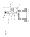
- a preferred further design of the lid is with a sampling device and internal riser pipe.
- the sampling device consists of a combination of two controlled three-way valves or ball valves, two controlled two-way valves and a vertical check valve with float body, in a fixed order, if necessary automated, must be switched. Automatic sampling during a process is necessary to monitor the progress of the reaction Track, control and control the synthesis time using analytics.
- the sampling device is e.g. connected to a riser pipe, which in the pressure-tight chamber immersed in the stirred reaction mixture of the individual container.
- the riser pipe end projecting into the container is open at the lower end, while at the other end of the riser pipe, outside the reactor space, the valve combination connected. There are several for controlled sampling Sequential switching operations of the valves necessary.
- the cover has a heating device on.
- a preferred variant of the device according to the invention is characterized in that that the heating device and / or the cooling device of the chambers of the chambers are separable.
- the pressure-resistant chamber e.g. one heater and one Cooling device provided at the same time.
- the temporal Delay until the start of energy dissipation can be shortened in which the Cooling device has direct contact with the pressure-resistant chamber.
- the energy supply by means of a heating device is preferably operated electrically.
- the heater is e.g. a hollow cylinder closed on one side, the inner one Contour of the outer, cylindrical contour of the pressure-resistant chamber is adapted.
- the heating device has e.g. a spiral groove to hold an electrical resistance wire with medium voltage (220V), but preferably with ⁇ 100V, particularly preferably with ⁇ 60V electrical Voltage is operated.
- the electrical heating wire encloses the entire Cylinder of the heater.
- a high temperature gradient between the pressure-resistant chamber and the heating device and to enable easy connection of the electrical heating a special embodiment is selected in which a spiral revolving Channel with two passages and adapted to the shape of the heating wire is so that the heating wire has an optimal metallic contact with the carrier.
- the heating device consists in particular of a material with a higher Thermal conductivity as the material of the pressure-bearing chamber. The quotient is formed from the thermal conductivity of the heating device and the pressure-resistant chamber is in particular greater than 1, preferably greater than 5 and particularly preferably greater than 10.
- the combination of electrical heating and high thermal conductivity of the The material of the heating device is a maximum for the chamber to be heated Heating gradient realizable, the short heating-up times for the process to be examined guaranteed.
- Preferred materials for the heating device are copper, brass, Aluminum or precious metals with high thermal conductivity.
- the heater can be part of the pressure-resistant chamber and be formed in one piece.
- the cooling device has, for example, the shape of a tube, the wall of which Has cavities for the flow of a tempering medium.
- the cooling device encloses the heating device in the cylindrical area in a preferred Execution completely, so that a close contact with good heat transfer through the heating device and pressure-resistant chamber.
- the material of the The cooling device is at least as good a heat conductor as the material of the heating device.
- the advantage is the separate Heating and cooling device visible if the cooling device is process-related directly encloses the pressure-resistant reaction chamber and the heating device Cooling device encloses. This can be an advantage in extremely exothermic processes be to further improve the dissipation of the heat of reaction.
- the energy supply The heater can quickly in this particular embodiment to be interrupted.
- the wall of the cooling device is hollow, so that a liquid or gaseous cooling medium can flow through the cooling device.
- the heat transfer surface is in the wall cavity the cooling device by ribs or preferably by a spiral channel or particularly preferably through a multi-channel, spiral channel.
- the cooling device can use multi-pass cooling channels simultaneously with air and / or water can be operated simultaneously.
- the heating / cooling device offers the possibility of very high heating rates and after Trying to realize high cooling rates so that the course of the reaction is only marginal or is not affected at all.
- the known ones offer this advantage Devices not. This effect is not the optimal design of the temperature control system, especially with parallelized miniaturization, so serious, that with very short reaction times, no meaningful chemical and process engineering Results can be derived from the experiment.
- the averaged temperature change (heating or cooling rate) of the heating / cooling system in particular at least 5 ° C / minute, preferably at least 10 ° C / minute and particularly preferably at least 15 ° C./minute.
- the Cooling device be part of the reaction chamber. This leads to something less Heat transfer resistances and improves the system-specific cooling performance at the expense of flexibility.
- the sample vessels are in another preferred design of the experiment device integrally formed with the chambers.
- the receiving unit in which the individual reactors are positioned is thereby Hinges or swivel joints added, so that a desired one manually Can be set tilt angle. This measure allows in the individual reactors Experiments with a total batch amount that is less than 1.5 ml without changing the technical equipment of the reactor system.
- each two adjacent individual reactors connected in series on different ones Height arranged.
- two neighboring series can be connected to each other Single reactors are operated under different pressure and in the Connection line between the individual reactors switched a conveyor unit his.
- the series connection of the individual reactors allows, in particular, the process engineering Questions in the parallelized synthesis of temperature-sensitive Investigate substances and improve the synthesis result in terms of selectivity. It can also be advantageous if a downstream single tractor has a larger volume than the upstream. Furthermore there is the possibility of the following cooling phase or cooling time after a defined synthesis time switch off the reaction mixture completely, in which the substance transfer in the downstream single reactor in the upstream and cooled neutral liquid.
- the individual reactors are used for the simplified feeding and removal of process materials connected to a fabric distribution unit.
- Fabric distribution units are required to perform an automated investigation Small-scale synthesis, chemical, physical, or process engineering Viewpoints. Because of the often very complex Apparatus for a quick examination close to the company and for changing ones A compact design is advantageous and necessary for tasks. Such tests are carried out at high pressure (up to 400 bar) and high temperatures carried out, it is the achievement of accurate, reproducible measurement results particularly difficult because of the complex parallelized experimental equipment there may still be many leakage options. The expert knows that every conventional detachable connection of material lines has a leakage rate and the respective amount of leakage multiplied by a large number of solvable pressurized connections cause test results to not match can and no reproducible measurement results can be achieved.
- a substance distribution unit is preferably one of at least one three lamellae (e.g. metal sheets) stack, the lamellae elongated holes or have circular openings. In the stack e.g. through several Elongated channels formed. The adjacent channels are horizontal a middle slat is not connected. The middle single lamella has a cover slat on the top and bottom, whereby on the top and or underside of the cover plate circular openings for the The supply and discharge of the substances are introduced.
- lamellae e.g. metal sheets
- the fabric distribution unit exists in particular from at least two slats of different thicknesses, the central lamella with its slits as channels is thicker than the two covering ones Slats with the inlet and outlet openings.
- the horizontal one The spacing of the slots in the middle lamella is dimensioned so that a complete Flat soldering of the two cover slats with the central, slotted one Slat, at least one pressure-resistant supply and / or discharge Process materials channel is created.
- the resulting stack of lamellas can be used as a fabric distribution unit for the chemical process but also as a distribution unit for Temperature control media can be used.
- One of the distributing channels branches Large number of smaller discharge openings to supply the individual reactors.
- the flow cross-section of the opening is as large as the flow cross-section of the distributing slot in the middle lamella.
- the flow cross sections the discharge openings are many times smaller than those of the discharge openings.
- a preferred embodiment of the fabric distribution unit is by direct Coupling a controllable valve with the discharge opening of a distributing one Slat channel realized. This can be controlled valves or ball valves screwed directly into the cover plate and sealed or welded onto it become.
- the fabric distribution unit can consist of different materials, so that Temperature, pressure and corrosion influences are sufficiently taken into account.
- the fabric distribution unit is made to be a solid unit forms, in special versions the unit is assembled from screwed slats, so that the introduced channels with each other with elastic Seals are separated from each other and sealed.
- the distributing channels are on top of each other in several levels and are marked through a straight row of outlet openings, in the previously described Embodiment, in a flat design, are the distribution channels parallel side by side in one plane and the emitting substance outlet openings are distributed unevenly on the front and back of the fabric distributor.
- the parallel spacing of the distribution channels in a horizontal position should be due to printing View at least one channel width, so in particular economic Soldering or welding technology, such as laser or electric beam method, can be used to connect the slats.
- the fabric distribution unit in a compact design consists e.g. out of at least 5 Plates or sheets, the sheets being structured differently. Under Structuring is of different sizes, circular openings (holes) or understand long and short slots (elongated holes). Are the sheets (slats) positioned one above the other and the contact surfaces of the sheets with each other e.g. the whole area connected to a laminated core, so created by the introduced Structures, horizontal and vertical rectangular flow channels (Cavities) with different flow cross sections, which differ in different Sections, but in different, separate levels, in the Cut 90 degree angles. The flow cross sections are starting at the main entry point of the respective distribution channel to the delivery point or to the exit point, where there is a special controllable plate valve, always smaller. This ensures an even distribution in the fabric distribution unit guaranteed up to the releasing valve of the liquid or gaseous media.
- Main lines can be located at the main feed point in the mass distribution unit for various gaseous or liquid energy sources such as water, air or cooling brine as well as gaseous or liquid reaction substances.
- the flow cross sections are dimensioned by a suitable choice of Sheet thickness and by defining the introduced surface structures.
- a modified version was used to simplify the experiment in parallel reactions preferred device developed in which the fabric feeds and drains and optionally pressure reducing lines (vacuum line) with one of the Above described mass distribution unit are connected.
- the supply lines, Discharge lines and, if necessary, pressure reducing lines of the individual reactors either with each other and / or with a main feed line Main substance discharge and possibly a main pressure reducing line connected.
- a material distributor composed of several, in particular at least, is particularly preferred three metal lamellae, firmly connected to each other, in layers one above the other built up, into the fabric channels and, if necessary, vacuum channels and inputs and outputs are incorporated.
- the uppermost one has and / or the lowest slat inputs for the external supply lines and outputs to the reactor lines and the middle lamella (s) has connecting channels.
- the flat fabric distributor with adapted apparatus components can also be referred to as a supply unit and is usually assigned to a single reactor.
- the preferably flat fabric manifolds can be combined with the compact fabric manifolds can be combined so that a flat material distributor is assigned to the single reactor and the compact material distributor is an upstream supply unit represents.
- a distribution unit can be a component a supply unit, the distribution unit having at least one feed point and has a plurality of associated exit points in parallel by several or to supply sequentially connected individual reactors.
- a supply unit is preferably provided for a multiple of two individual reactors.
- the supply unit serves to accommodate various procedural Components to carry out a test efficiently, automatically and reproducibly perform.
- Process engineering components e.g. Storage tanks, filter devices, thermal separation units, heat exchangers, Conveying and dosing units as well as safety devices such as safety valves and rupture disks.
- safety devices e.g. safety valves and rupture disks.
- Sensors but also online sensors, are installed by as many as possible to get different measured values from the process processes in the single reactor.
- Process engineering apparatus components need different ones to perform their functions Supply connections, e.g. for electrical energy, cooling by Water or air, pressurizing the product space with inert gas and, if necessary other safety devices such as pressure relief valves or rupture disks.
- controllable valves for applications up to high pressure ranges for the automated operation of parallelized Syntheses developed. These are so-called plate valves that have an integrated one Own control head.
- pneumatically controllable plate valves are e.g. at every exit point of the compact fabric distribution units attached and are in a preferred embodiment executed as a detachable stack of individual plates.
- the releasable Plates of the valve are also structured, the structuring being in the essentially limited to circular openings of different sizes. Some plates of the valve have horizontal channels. These serve the Product infeed or outfeed.
- the valve has a head plate, in which a pneumatic controllable sealing cylinder with attached valve spindle is used.
- plates or sheets of a valve are among one another equipped with interchangeable elastic seals, the seals usually perform two functions.
- the double sealing function consists of a sealing effect from the product space of the valve to the controlling one Pneumatic chamber at the head of the valve and at the same time for sealing the plates with each other and with the atmosphere.
- the valve's plate rod will directly connected to the fabric distribution unit with screws.
- the areas of the Pneumatic cylinder used for control, i.e. for moving the valve stem up or down or for opening and closing the valve are at least around Factor 10 larger than the pressurized effective area of the valve stem in contact with the medium, this results in an area pressure ratio.
- the area effective pressure ratio is > 10 and in a further particularly preferred embodiment, the area pressure ratio is > 50th
- valve So that if the compressed air fails, the valve automatically returns to the desired one switches safe state, is in a special embodiment under the Cylinder a space-saving disc spring attached.
- the valve can due to the lamellar plate structure can be easily modified so that it is in other embodiments as manually operated, hydraulically controlled or electromagnetically controlled Valve can be executed.
- the fabric distribution unit with the required Valves can be expanded by a multiple of the number of main channels. The Area of application in terms of temperature and pressure meets the high requirements of the parallelized individual reactors.
- the reduced version of the plate valve with integrated controllable head has very short response times due to the small control air spaces, so that extremely short switching times can be realized.
- a particularly preferred design of the device according to the invention is consequently characterized in that the outputs of the substance distributor with the supply lines or connected to the derivatives of the individual reactors via switchable or controllable valves are.
- valves are in particular directly connected to the material distributor.
- valves are preferably designed to be pneumatically controllable. Particularly preferred the valves are designed to be self-locking if the pneumatic control fails.
- control unit mentioned above controls or regulates in addition to temperature and Pressure also prefers the speed of the stirring devices and / or the position of the Valves.
- the sample vessels are designed to be separable and are either between the top of the sample tubes and the Chamber wall or between the lid wall and the upper edge of the sample vessels an additional sealant is provided.
- the control unit is preferably part of a process control system and provides e.g. represents a temperature sensor. In addition, the control unit as an additional pressure sensor used.
- Control units can be used in sufficient numbers per reactor system and used in parallel, with the connection to the actual Process control system and a connected computer with appropriate software for regulating and controlling the chemical, physical and process engineering Processes are carried out using circuit board technology that is known in principle. With conventional multi-core ribbon cables are e.g. Control units and actuator units connected to the process control system and exchanged analog and digital signals, signal values also meanwhile mathematically specific to the process processed and thereby new control signals or commands are generated. Digital signals are mainly used to control control valves and as monitoring signals used.
- the process control system can also be a controller or be a multi-channel controller, with essential process information being lost can.
- the process control system can also be a controller or be a multi-channel controller, with essential process information being lost can.
- good reproducibility is one Basic condition, i.e. that little or no intervention by the operating personnel may take place. Interventions by changing operating personnel lead to errors and falsify the test results.
- the individual software units are combinations of control functions and / or Control functions. They are e.g. stored in a software library so that the Users to carry out a specific test procedure Take software units from the library, link them together as required and structure and in a row according to the desired test sequence can interconnect.
- the user also has the option of all individual reactors with the associated devices on the supply unit in parallel to control and regulate with the same parameters, but there is also the option Possibility to control all parallel units with different parameters and operate.
- the device according to the invention and the method offer compared to the state technology has the advantage that its modular structure makes it quick and economical Adaptation to the technical result of any question Requirements can be made.
- the device offers the possibility, too under extreme test conditions while maintaining the technical Rules to grant security to conduct experiments.
- Another An advantage over the known prior art is the possibility of the implementation of the process to control each individual reactor individually, in particular by supplying or removing energy. This is e.g. also the Handling of tendencies that tend to run away, i.e. strongly exothermic possible. This is not possible with known devices of the prior art.
- the material distribution unit enables the distribution of material and energy flows to all reactors in a confined space.
- a particularly preferred embodiment of the device is characterized in that that the device has a modular structure, the individual reactors being the heating device, the cooling device, the control unit, the stirring device, if necessary the substance distribution unit and, if applicable, the supply unit, independently are interchangeable.
- the preferred inclination of the entire reactor block makes it possible the use of sample quantities consisting of liquid and solid to further reduce efficient mixing.
- the volume of the reaction mixture can reduced to ⁇ 5 ml ( ⁇ 1ml). In these cases it is special advantageous by exchanging individual modules to meet the test requirements in a simple way adapt.
- the size of the batch essentially also determines the detection of an exothermic reaction. The total mass of the surrounding chamber, Heating and cooling units must not lead to the reaction-related Temperature rise is suppressed, and so the exothermic is not recognized and evaluated can be.
- the use of a mass-optimized heating and cooling unit with two drawers spiral cooling channel enables targeted countermeasures of the reaction temperature in the reaction chamber, in the form that first with a cooling medium can be cooled with low heat absorption capacity and only at insufficient cooling capacity, a second cooling medium is connected in parallel can be used to stabilize the process in terms of temperature.
- this cooling method only becomes the miniaturized process control of exothermic Reactions with small reaction batches ( ⁇ 5ml) enabled.
- the special fabric distributors enable the even distribution of fabric and energy flows to all reactors in a confined space. Because of the special lamellar structure of the module and the use of very compact, for extreme conditions suitable valves, the number of connection points and thus possible leakage points at high pressures, as well as the length of the required Capillary lines drastically reduced, resulting in a larger overview, high operational reliability and thus for a simple and safe handling of the invention Device leads.
- the special design of the preferred ones controllable valves with e.g. integrated pneumatic drive in the field of Valve head plate significantly reduces the response or switching times of the valves. Furthermore, for automated holistic test sequences of parallelized Reaction systems very many controllable valves required the smallest Space must be accommodated. It is not uncommon for up to 10 valves per Reactor required, so that the tailored valve design is much more economical and is cheaper than conventional solutions with known valve types.
- the supply unit On the supply unit the additional miniaturized, apparatuses required are concentrated Reactor periphery in order to be able to carry out a test fully automatically. These include various additional miniaturized devices, such as Storage tank, Buffers, filtration units, mixer settlers, on-line analysis, pumps and others Valves and the required sensors and actuators for the measurement of physical Parameters.
- the supply unit can also be part of a liquid handler be positioned in a glove box if necessary. This is one Handling liquids and solids possible under inert conditions. This makes it possible to carry out the sample preparation directly with the parallel execution of the experiment to link.
- the control unit e.g. consisting of sensor and actuator board
- the control unit can be directly on the Supply unit must be positioned so that short electrical cable routes are possible become. Due to the large number of different sensors and actuators Up to 500 so-called MCR points interconnected and bundled via multi-core ribbon cables to the process control system. This modular technology saves space, Costs and produces flexibility when using different sensors for different Questions in the parallel execution of the experiment. In particular with changing tasks is an easy retrofitting or conversion possible.
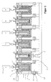
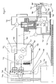
- FIG. 7 shows an overview of the different parts of a test device and their interconnection is shown, e.g. the modularly constructed single reactor 1 with a cover module 22, the fabric manifolds 702, 702a with the plate valves 704 and the supply unit 701, which is designed here as a simple mounting plate.
- the supply unit 701 is with integrated main distribution channels formed as a flat fabric distributor 80 (see Figure 8) and assigned to at least one individual reactor.
- interface modules 714, 724 provided in the form of the sensor and actuator board, which in turn is on the control unit 700 and a PC (not shown) is connected.
- FIG. 7 It can be seen in FIG. 7 that there is a sample vessel in the individual reactor 1 and a magnetic stirrer 4 is used, which is by an external magnetic coupling is driven by a motor.
- the modular structure of the single reactor 1 is with another stirrer device 4 in Figure 1 described below.
- a substance distribution unit 702 is connected to the heating / cooling module of the individual reactor 1, e.g. two feeding material channels, e.g. for cooling water 711 for cooling air 712 a channel 721 for the joint discharge of the cooling air and the Cooling water.
- Each individual main distribution channel (711, 712, 721) of the substance distributor 702 has, corresponding to the number of individual reactors installed in parallel Feeding or discharging outputs 707, which are with controllable valves 704 are equipped.
- Additional process engineering components are, for example, a container 708 to keep a reaction component ready at the time of the synthesis start with controllable valve 704 open with a pump 720 of the reaction in the individual container 1 can be added, and a pressure fuse in the form of a rupture disc 709 which secures the individual container against overpressure.
- a substance distributor 702a is included to carry each individual reactor 1 a supply and discharge capillary 725 with e.g. Nitrogen 713, vacuum 706 and to provide a ventilation option 727.
- the same fabric distributor 702a as Shown in FIG. 7 can also assume the task of container 708 to be evacuated, rendered inert or aerated with filling valve 716 and additionally the connect the discharge pipe of the 709 bursting disc.
- On the supply unit is to control the pressure in the individual reactor 1 and Container 708, for example, each have a sensor 717 connected to the ventilation line.
- the interface module 714, 724 is in the form of Sensor and actuator board close to the respective individual reactors and required process engineering Components positioned.
- the interface modules are connected to the control unit by a 715 multi-core cable 700 connected to which the personal computer (PC), which is not shown here, connected. Due to the sometimes very complex tasks the number of measuring and control points of the overall device quickly to more than 200 climb.
- control unit 700 With the control unit 700, the described software units and the PC communication with the chemical process engineering process, so that the measured signals can be mathematically transformed and calculated, to generate new control signals and thus control the process.
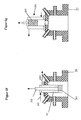
- the structure of the individual reactor 1 is shown in FIG.
- the single reactor 1 is itself modular and is made of the pressure-resistant chamber 2a, in which a sample vessel 12 is used to receive the process substance 10, formed.
- On the pressure-resistant chamber 2a is a depending on the procedural task specially designed pressure-resistant cover 21 positioned.
- One is placed over the lid Stirring device 4 and a temperature sensor 7 in the sample vessel 12 with the process substance 10 submerged.
- a seal between the chamber 2a and the cover 21 is inserted.
- the flameproof lid has at least one supply line 8 and a discharge line 9, via the substances against pressure can be initiated or discharged.
- an electric heating device 31 In the lower part of the single reactor 1 there is an electric heating device 31.
- the heating device 31 has on the outer circumference at least one spiral groove 31 a, into which the electric heating wire 31b is inserted to lead the desired heating energy to the individual reactor 1 can.
- the heating device 31 completely surrounds the bottom of the individual reactor 1, so that even with small amounts to be examined the available standing heat transfer surface is sufficiently large.
- the heater 31 is enclosed by the cooling device 32.
- the cooling device 32 has a double jacket, which encloses a cavity 32a, in which a feed line 32b for the supply of a temperature control or coolant and a discharge 32c for the Removal of the temperature control or coolant opens.
- the outer circumference of the lower part of the single reactor 1 has metallic contact with the heater 31 and the heater has metallic contact with the Cooling device 32 so that good heat conduction between the individual metallic Components is guaranteed.
- the temperature sensor 7 shown is connected to the control unit 700 (see FIG. 7) connected.
- the columns 214 of the receiving unit can be designed as a hinge, so that the entire reactor system with closure unit at an angle ⁇ of 5 to 60 ° can be pivoted and fixed with the screws 212 and the nut 213.
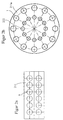
- FIG. 2a shows that the number of individual reactors 1 increases slightly 12 individual reactors can be increased by the recording unit 211 in addition expanded in parallel, or another form of the recording unit is selected, e.g. a circular arrangement 211a ( Figure 2b) with associated substance templates 222nd
- the locking latch is special is shaped and has a claw 1111, which is in the open state of the locking bolt between two lids (e.g. 23) so that one operator can operate each individual reactor 1 can be opened by removing the cover (e.g. 23).
- the cover flange has a phase 2310 which enables that when locking (see Fig. 2c below) by the pneumatic or electric drive the claw 1111 over the phase 2310 can slip on the surface of the cover flange 23 to the required Sealing force on the inserted seal between the pressure-resistant chamber of the individual container 1 and cover 23 to apply.
- the closing path of the locking bolt 11 is half the individual reactor center distance X.
- FIG. 2d shows the section A-A from FIG. 2c of a locked individual container 1. Zu Recognize phase 2310 on the upper flange of cover 23 and that the locking claw 1111 in the final state presses the lid 23 onto the chamber and thereby the inserted seal pressed together.
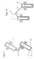
- FIGS. 3 and 3a 1 A serial connection of two individual reactors is shown schematically in FIGS. 3 and 3a 1 (in adjacent recording units), with a in the height offset arrangement of the individual reactors 1 and 1a by a connecting Capillary 311 and an intermediate feed pump 312 (Fig.3a) and one interposed controllable valve 313 ( Figure 3).
- the chamber of the reactor 1a is formed in one piece with the Sample vessel.
- the planar bottom has an angle ⁇ of 30 ° to the horizontal ( Figure 3).
- the heater 31 has on the outside Perimeter a spiral groove 31a, the groove bottom of the shape of the electric heating wire 31b is adapted to a good contact area and heat transfer to reach.
- FIGS. 4a, 4b and 4c show further alternative designs for the heating / cooling device 32 shown.
- the cooling device 32 in FIG. 4a has a double jacket, one concentric cavity 32c with feed line 32a and discharge line 32b encloses for passing a cooling or tempering medium.
- the concentric cavity 32c is shown in FIG. 4b specially trained.
- the tempering cavity 32c was formed by a spiral channel. 4c is an embodiment with two Spiral temperature control channels 32e, 32d shown. Every temperature control channel has a feed line 32d and a discharge line 32b.
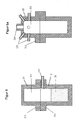
- FIGS. 5 to 5e show different embodiments of the pressure-resistant ones Chamber shown.
- the pressure-resistant chambers are with the lids 21-29 optionally combined to form a pressure-tight reactor unit 1.
- the cover 21 is in the form according to FIG. 5, in a special form without an inner one Cavity, with the pressure-resistant chamber 2 and an inserted sample vessel 12 see.
- the insertable sample container 12 is on its outer side Circumference sealed with an elastic O-ring.
- the chamber 2a has below the inlet and outlet opening of the feed line 131 and discharge line 132 is an integrated one Groove 134 for receiving the elastic seal 51.
- the chamber 2b is on the contact plane to the cover 21 provided with a rotationally symmetrical recess 133 for receiving a elastic or a metallic seal.
- the pressure-resistant chamber 2c has at least one Supply line 131 and / or at least one discharge line 132 shown.
- the used Sample vessel 12 is closed with a septum 136 and additionally with a capillary 137 provided for a possible pressure compensation between pressure-resistant Chamber 2c and the interior of the sample vessel.
- the chamber 2d has no product connections and the sample vessel lies closely against the inner wall of the chamber 2d.
- the concentric A groove 135 can be inserted so that the adjacent one Cover 22 seals the interior of the individual reactor against excess pressure.
- the chamber 2e is made with an inert, corrosion-resistant material (enamel) coated so that no sample vessel 12 is required for the experiments to be carried out becomes.
- enamel corrosion-resistant material
- FIGS. 6 and 6a-i the interchangeable cover 21, Across 29 shown.
- the many alternative cover modules make the flexibility in terms of different chemical and procedural issues and experimentation clearly.
- the simplest embodiment in the form of the lid 21 is connected shown with the chamber 2 and the associated test room 20.
- the Chamber 2 does not contain a separable sample vessel 12.
- the inside of the lid 21 is elaborated so that the cavity 211 forms.
- the test room is formed from the cavity 211 and the test room 20.
- Substance supply or discharge connection lines 213 are in the chamber 2 intended.
- the required seals are not shown in FIG horizontal flange area of lid and chamber.
- a stepped Concentric flange 212 formed on the lid, which with the stepped outer ring 202 of the chamber 2, the sealing forces for the pressure-tight closure of the Test room.
- FIG. 6a shows a variant of a single reactor 1 with a modified cover 22 shown.
- the illustration of the cover 22 shows the test room 221 with the stepped flange 212 and further separate supply or discharge capillaries 223, or openings for connecting small pipes, which are in the cover 22 directly are welded in.
- One of the openings 223 can be used directly Use thermocouple for indoor temperature measurement.
- an opening 224 is generally provided, which also allows larger ones to adapt other components.
- Figure 6b shows the cover variant 23 with a thermometer protection tube 235 for Inclusion of a temperature sensor for indoor temperature control, and an in the stirrer protruding into the test room as well as further supply lines and discharge lines 238.
- the agitator consists of the agitator shafts 231 with agitator blade 233, the Stirrer shaft in the upper area and outside of the cover through a sealing area 237 is guided and the seal sits in a pressure-resistant housing 236.
- Sealing materials and types can be elastic O-rings as well as temperature-resistant Gland packings or shaft seals are used.
- the stub shaft that protrudes from the housing 236 takes e.g. a non-positive Coupling 232 and thus creates the connection to the stirrer drive 234. With this lid variant in particular high stirring performance can be achieved mixing reaction mixture are transferred.
- FIG. 6c shows the cover 24 with an addition in its construction compared to cover 23 from Figure 6b for the process engineering application of direct gas introduction through a hollow stirrer shaft 241 (detail Fig. 6d).
- the hollow agitator shaft 241 has an opening 242 on the shaft head for introducing a substance into the interior of the stirrer shaft and at the same time the stirrer shaft on the foot is open, so that the introduced substance can be fed directly to a synthesis.
- Around an additional housing 245 is provided with this opening area of the agitator shaft head Seals 244 (see FIG. 6d for an enlarged detail) are necessary to ensure that the supply Substance that can be liquid or gaseous does not get into the environment.
- the Additional housing 245 with the seals 244 can alternatively directly on the Lid are mounted (not shown), then the housing 236 with the Seals 237.
- Figure 6e shows a design of a suitable stirrer shaft bushing for a Reactor cover as in Fig. 6c.
- the contour of the cover 25 is not shown here, but only the double-walled hollow stirrer shaft 259 to be adapted direct additional temperature control of the substances used.
- the double-walled The hollow stirrer shaft is closed at the base, the hollow shaft has on Head an inflow opening 252 from a concentric supply area 253 in the housing 255 supplied with the temperature control medium via the feed 251 becomes.
- the outer jacket of the double-walled hollow shaft stirrer has an outflow opening 256, of which the temperature control medium in the concentric groove 254 Housing 257 leaves.
- the housing and the double-walled hollow agitator shaft sealed with elastic seals 258 to the atmosphere and the test room.
- On the double-walled hollow shaft stirrer head there is a stub shaft 259 for Recording the clutch for a drive unit is provided.
- FIG. 6f shows a further variant of a reactor cover 26 with a cooler 261 shown, which protrudes into the interior of the cover 26.
- the cooler 261 has in the center a through channel 262 for the discharge or introduction of a reaction component, which, for example, when passing through the cooled through-channel is tempered.
- the internal cooler 261 also has the task of volatile Reaction components in the gas space or test space of the cover 26 condense. Therefore, additional cooling fins 263 are attached to the base of the cooler, which significantly increases the cooling surface.
- the supply connections 264, 265 for the supply and discharge of the internal temperature control Radiator 261 are outside the lid.
- the cooling fins 263 can in a not shown representation on the cylindrical circumference of the cooler in Lid cavity to further increase the cooling surface.
- the inside Cooler 261 can be flanged to the lid as an independent component. However, in order to save additional seals, the cooler is in the embodiment shown firmly connected to the cover 26 by welding.
- FIG. 6g A comparable other design of a cover with cooler 261 is shown in FIG. 6g.
- the cooler is arranged outside the cover 27, the cooling fins 263 are positioned inside the cooler.
- the external cooler position has the The advantage that due to the spatial freedom, the cooling unit is very large can be. There is also the option of replacing the cooler position the thermally separable thermal separation unit on the cover 27.
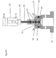
- the cover is 28 provided with a metering device 285 in the form of an annular gap metering device.
- the Annular gap metering device has an adjusting unit 281 in the form of a pneumatic cylinder.
- a coupling piece 282 is on the piston of the cylinder the metering piston 283 fastened with the dynamic annular gap 284.
- Is the adjustment unit 281 retracted, is located around the dynamic annular gap 284 of the Piston 283 in the housing 285 of the annular gap metering a concentric static Annular gap 286.
- Both annular gaps 284 and 286 form in the retracted state Pistons have a common large concentric flow area.
- the dosing piston 283 has at least above the dynamic annular gap 284 of the dosing device two elastic seals 287 and at least below the annular gap 284 an elastic seal 288.
- the seal 287 leaves during a metering stroke the adjusting unit 281, the housing 285 of the dosing device.
- the Seal 288 leaves the housing of the metering device during a metering stroke 285, and is in the extended state of the adjustment unit in the lid cavity.
- the concentric static annular gap has a supply opening 289 and a laxative opening 281. Since the concentric static annular gap 286 is larger than the dynamic annular gap 284, it forms a bypass channel, so that it is possible to have a constant flow independent of the piston position the dosing device with e.g. Realize reactant.
- the variant of the reactor cover according to FIG. 6i is a cover 29 with a sampling device 291.
- the sampling 291 is connected to an internal one Riser pipe 292 and also has a combination of controllable valves.
- the valve 293 is located directly on the riser pipe 292, above which is a three-way ball valve 294 arranged, which is horizontally connected to the ball valve 295.
- Vertical A check valve 297 is located above the three-way ball valve 294 a closing body which is designed as a float and another one Three-way valve 296. With rising liquid from the reaction chamber the closing body floats and is in the sealing seat of the check valve 297 pressed.
- the valve 296 connected to the check valve 297 is in the Moment to a vacuum generator (vacuum side) and to an inert gas supply (Pressure side) connected, whereby the pressure of the inert gas supply is greater must be than the prevailing internal reactor pressure at the time of sampling.
- the Valve 295 is connected to the outlet with an appropriate analyzer (e.g. HPLC) connected.
- FIG. 8b shows a special embodiment of the supply unit described in FIG. 7 701, as a flat material distributor 80, which also serves as a supply unit serves, with integrated main distribution channels 84 for the supply of Single reactors 1 e.g. with particularly toxic substances.
- FIG 8b the material distributor 80 with integrated distribution channels 84 in the Top view shown schematically.
- This simple embodiment shows one flat material distributor with a significantly reduced number of possible leakage points, to supply the required process engineering components for the single reactors 1 operated in parallel is used.
- Figure 8 is a partial section along line A-A in Figure 8b of the specially designed Substance distributor 80 shown.
- Three metal fins 81, 82, 83 can be seen, which are fully soldered together So that the slots 84 in the Slat 82 closed, so that the slat package is a monolithic channel system with several pressure-resistant main distribution channels.
- FIG. 8a shows the longitudinal section through the material distributor 80 of the main distribution channel 84 with a feed opening 85 and a plurality of discharge openings 86, to which controllable valves 704 are connected.
- the 704 controllable valves can be welded into the upper lamella 81 on one side, or firmly with screws connected to the fabric distribution unit 80, which is designed as an assembly unit, screwed valves 704 with an elastic seal, not shown here are sealed to the supply unit.
- FIG. 9 shows the special embodiment of a specially developed plate valve shown.
- the valve is connected to a compact fabric distribution unit 702 with separate main distribution channels, with the taps of channels 97 and 98 cross each other on separate levels.
- a branching channel 910 is screwed on directly the plate valve 704.
- the fabric distribution unit 702 here consists of six metal fins (91-96), with five lamellas structured by recesses.
- the Slats are adapted to the valve width in a narrow range from the feed Main main distribution channels 97-99 three branching channels 910 with controllable To be able to equip the valve.
- the connection point of the fabric distribution unit 702 and plate valve 704 is with an elastic seal 917 to the environment sealed. Of the plates 911-916, the plate 915 provides an elastic flat seal represents that seals the pneumatic space.
- the plate valve 704 has six plates and one in this embodiment internal offset cylinder with spindle 918.
- the internal cylinder with spindle 918 sits in several elastic seals 919, 920, 925, the Seal 925 in part 911 simultaneously forms the sealing seat of the valve and in the closed Condition the material passage from the main distribution channel 97 - 99 to the Outlet channel 927 of the plate valve 704 prevented.
- the seal 919 seals the from the valve's product contact area to the control head, the pneumatic one Compressed air space or to the environment.
- the seal 920 closes the controlling one Compressed air space 921 of the cylinder 918.
- the head plate 916 which at the same time Receiving cylinder 918 with an elastic seal 922 has two connection openings 923, 924 to supply the cylinder with control air.
- connection opening 923 causes the cylinder with spindle to be supplied with compressed air is lifted and the shaped cylinder tip from the elastic Sealing seat 925, (Fig. 9b) is raised and the material flow is free. Does that happen Compressed air supply via the connection opening 924, with simultaneous relaxation of the Compressed air connection at opening 923, so the cylinder with spindle in the elastic sealing seat 925 pressed down and the material flow is interrupted.
- the amount of substance flowing through depending on the cylinder position leaves the plate valve via channel 927. At the exit point of channel 927 there are further components such as capillaries, containers, temperature control elements or the individual reactor directly connected.
- the cylinder 918 provides different sizes due to existing Pressure application areas represent a pressure intensifier.
- the largest pressure in usually a process pressure, affects the smallest area at the spindle tip and the controlling pressure, usually the compressed air, on the largest area on the cylinder head.
- the plate valve can be connected to hydraulic supply systems for the control, which can generate significantly higher pressures become. In these cases, the top effective area of the cylinder can be significant be smaller.
- Figures 9a and 9b show identical plate valves 704, on the common compact material distribution unit 702, with several plate valves 704 in a row are mounted on the distribution unit 702 and with the same main distribution channel are connected.
- FIG. 10 shows the combination of those used for carrying out an experiment different software units are shown schematically.
- the operator can use the library in which all software units are stored compile his specific test execution according to the software units, by copying the required software units from the library and opening them a worksheet and connects them together.
- a typical test sequence is composed as follows. On the software unit 1002 "system check” follows the software unit 1003 "leak test” for all reactor units. All Reactor units are rendered inert using a sensitive process the software unit 1004. The inerting takes place by displacement or dilution of the chamber contents.
- the operator further desires that e.g. three Reactor units with a temperature of 100 ° C, using the software unit "Tempering" 1006 and three reactor units operated at a temperature of 130 ° C should be. Furthermore, the synthesis should be in the individual containers below constant stirring, with the software unit 1007 "stirring".
- a pressure-controlled substance dosing with software unit 1008 also follows "Dosing" with selectable dosing strokes per attempt.
- the submitted liquid base polymer and the reaction accelerator are by means of a Weighing scales were poured into rolled-edge glasses, then the rolled-edge glasses were inserted into the respective individual reactors 1 and the sealing covers placed, to automatically close the pressurized ones To enable individual containers.
- the modular test system consisted of six arranged in parallel Single reactors 1 (Figure 2) with a test room volume of about 25 ml, wherein the individual reactors 1 with one for the process engineering test request required cover variant 28 according to the invention (FIG. 6h) and a temperature sensor 7 were equipped.
- Six individual reactors are in one Recording unit 211 (FIG. 2) with a locking bolt 11 working simultaneously, which is provided with a pneumatic drive 11c used.
- a sample vessel 12 served a rolled rim glass in which a magnetic stirrer is inserted.
- the Magnetic stirrer was with an electric motor 4 and a magnetic coupling (Figure 2) driven, the drive being positioned below the single reactor.
- the Individual reactors had the electrical heating device 31 according to FIG.
- the heater 31 was two further temperature sensors 7 equipped to the possibility of cascade control according to the internal temperature of the individual container and the second Temperature sensor served the so-called overtemperature protection (integrated Security) that should allow, during an automated driving style, on a Waive personnel monitoring.
- integrated Security integrated Security
- the pressure-resistant chamber 2a (FIG. 5a) was in the flange area for this application provided with leads 131 and leads 132.
- Fabric distributor 702 (similar to Figure 9) with directly attached plate valves 704 installed to supply the six individual reactors.
- a fabric distributor with The cooling device supplied three main distribution channels, for example Distribution duct 97 for the cooling air supply, duct 98 for the cooling water supply and channel 99 was used for the discharge of both coolants.
- the Leaking lines 32b ( Figure 4b) of the cooling module were combined and directly connected to the fabric distributor, so that none for the discharge duct 99 controllable plate valve was needed.
- the second compact fabric distributor is used to supply the individual containers.
- the main distribution channels 97, 98, 99 were used for the following task; channel 99 for connection to a vacuum pump, channel 98 for the supply of nitrogen and duct 97 for targeted ventilation of the individual reactors.
- the supply line and derivation of media for the individual reactors 1 was carried out in this experiment at different times. That is why all the outlet openings of the fabric distributor were equipped with controllable plate valves and the fabric outlet openings 927 ( Figure 9) of the plate valves together with a connection opening of the pressure-resistant Chamber connected. Another connection opening in the flange area of the pressure-resistant chamber served to connect a pressure sensor 717 and an automatic safety device 709 ( Figure 7).
- This supply unit or plate contained the following components: the multi-position valve, which the ring gap dosing device sequentially with liquefied Monomer supplied, the inclusion of the electro-pneumatic valves for control the piston in the annular gap dosing devices, the main drainage channels of the single reactor aeration and the outlet openings of the automatic safety devices (Bursting discs) to the central disposal units of the laboratory.
- the software units 1002, 1003, 1004, 1005 were linked in series and had to be completely processed to run the software modules connected in parallel Tempering 1006, stirring 1007 and dosing 1008 - the actual experiment, namely the polymerization - to be able to start.
- the synthesis was done after shutdown the single reactor heaters started by reaching the set one Inside the reactor the software module dosing 1008, here especially with individual preset number of parts and total strokes for each individual reactor has been.
- the total dosing stroke rate set for each individual reactor was reached the test in the respective reactor was ended with software module 1009.
- the data transmission 1010 and the ready report 1011 took place, so that the Operator could open the parallel reactor system without danger to the sample vessels can be taken and fed to the analysis.
- the automated driving style was chosen so that the tests can be carried out directly in one Technical center scale can be transferred.
- the chosen and used Security devices and controls left a largely personnel-free Test execution too, so that only a few manual interventions to prepare the parallel attempts were necessary and thereby the error rate individual influences of the experimenter could be reduced accordingly.
Landscapes
- Chemical & Material Sciences (AREA)
- Health & Medical Sciences (AREA)
- Chemical Kinetics & Catalysis (AREA)
- Clinical Laboratory Science (AREA)
- Organic Chemistry (AREA)
- Analytical Chemistry (AREA)
- General Health & Medical Sciences (AREA)
- Hematology (AREA)
- Physical Or Chemical Processes And Apparatus (AREA)
- Automatic Analysis And Handling Materials Therefor (AREA)
- Sampling And Sample Adjustment (AREA)
- Apparatus For Disinfection Or Sterilisation (AREA)
Abstract
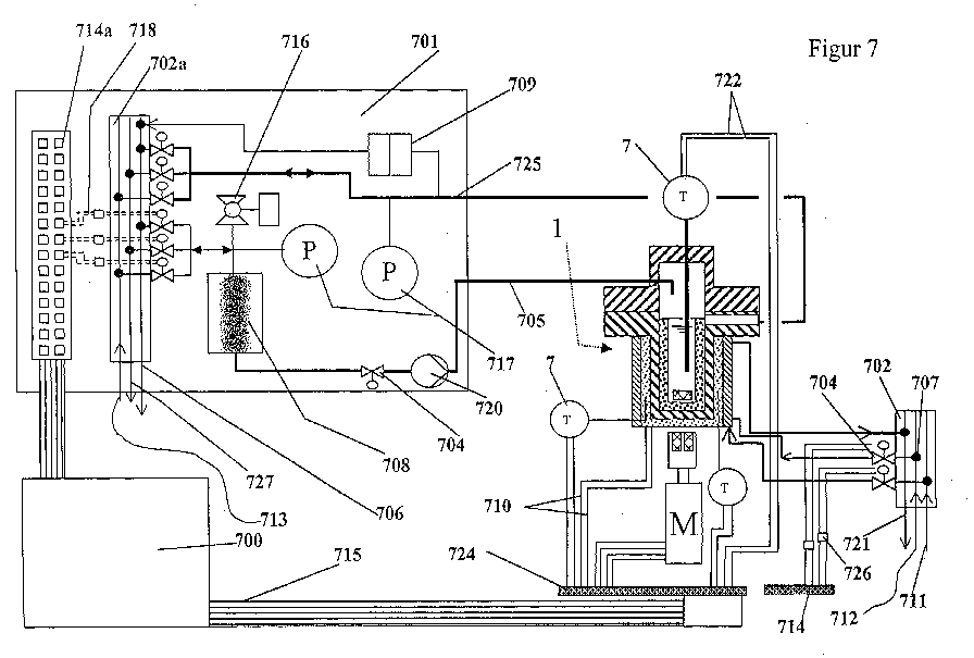
Description
- der Umsatz einer chemischen Reaktion
- die Selektivität einer chemischen Reaktion
- die Ausbeute einer chemischen Reaktion
- die Alterungsbeständigkeit einer Substanz
- der Viskositätsverlauf einer flüssigen Substanz / eines flüssigen Substanzgemisches
- der Energieverbrauch
- die Energieerzeugung
- der Temperaturverlauf
- der Druckverlauf
- die Löslichkeit
- die Korrosion
- die Wärmebeständigkeit
- Figur 1
- den Aufbau eines Einzelreaktors 1
- Figur 2
- den Querschnitt durch eine Versuchsvorrichtung mit sechs Einzelreaktoren in einer Aufnahmeeinheit
- Figuren 2 a, b
- zwei Varianten für eine Aufnahmeeinheit
- Figuren 2c, 2d
- Darstellung der Verschlusseinheit im geschlossenen und geöffnetem Zustand
- Figuren 3 a, b
- Beispiele für die serielle Kopplung zweier Einzelreaktoren in benachbarten Aufnahmeeinheiten
- Figur 4
- einen Querschnitt durch einen Reaktor mit elektrischer Heizung
- Figuren 4 a, b, c
- Beispiele für modulare Heiz-/Kühleinrichtungen
- Figuren 5, 5 a-e
- im Querschnitt verschiedene modulare Formen der Kammer 2 bis 2 e des Einzelreaktors 1
- Figuren 6, 6 a-i
- im Querschnitt verschiedene modulare Bauformen der Deckel 21 bis 29 des Einzelreaktors 1
- Figur 7
- eine schematische Übersicht über eine erfindungsgemäße Versuchsvorrichtung
- Figur 8
- den Querschnitt durch eine Stoffverteilereinheit entspr. Linie A-A in Figur 8 b
- Figur 8 a
- den Längsschnitt entsprechend Linie B-B in Figur 8 b
- Figur 8 b
- eine Aufsicht auf eine Stoffverteilereinheit
- Figuren 9, 9a, b
- den Querschnitt durch die Stoffverteilereinheit 702 mit darauf montiertem Plattenventil 704
- Figur 10
- ein Blockschema zur Erläuterung der Softwaremodule für eine Versuchsdurchführung
- Systemchek 1002
- Dichtigkeitsprüfung 1003
- Inertisieren 1 mit Vakuumfahrweise 1004
- Stickstoff-Vordruck 1005
- Temperieren 1006
- Rühren 1007
- Dosieren 1008
- Versuch beenden 1009
- Datenübertragung 1010
- Fertigmelden 1011
Claims (29)
- Vorrichtung zur parallelen Durchführung von Experimenten an Prozessstoffen für die Entwicklung von technischen Verfahren, insbesondere von chemischen und physikalischen Verfahren bestehend wenigstens aus einer Vielzahl, insbesondere mindestens 6, bevorzugt mindestens 12, besonders bevorzugt mindestens 24 Einzelreaktoren (1) zur Aufnahme der Prozessstoffe (10), wobei die Einzelreaktoren (1) unabhängig voneinander wenigstens bezüglich ihres inneren Drucks und ihrer Temperatur steuerbar oder regelbar sind, dadurch gekennzeichnet, dass die Einzelreaktoren (1) mindestens aufgebaut sind aus:je einer druckfesten Kammer (2, 2a, 2b, 2c, 2d, 2e,) mit einem separierbaren Probengefäß (12), gegebenenfalls je einer Rührvorrichtung (4),je einer Heizeinrichtung (31) und/oder einer Kühleinrichtung (32) zur individuellen Temperierung des Probengefäßes (12),einer Kontrolleinheit (700) zur Kontrolle oder Regelung wenigstens des Drucks und der Temperatur in den Einzelreaktoren (1),je einem druckfesten Deckel (21; 22; 23; 24; 25; 26....29), wobei die einzelnen Deckel (21; 22; 23; 24; 25; 26;....29) und/oder die Kammern (2, 2a, 2b, ..... 2e) unabhängig voneinander Zuleitungen (8) und gegebenenfalls Ableitungen (9) für einzelne Prozessstoffe aufweisen, und mehrere Deckel (21; 22; 23; 24; 25; 26....29) der Kammern (2, 2a, 2b, 2c, 2d, 2e,) mittels eines gemeinsamen Verschlussmittels (11) simultan verschließbar sind.
- Vorrichtung nach Anspruch 1, dadurch gekennzeichnet, dass das Verschlussmittel ein Verschlussriegel (11) ist, der pneumatisch, hydraulisch oder mittels elektrischem Antrieb verriegelbar ist.
- Vorrichtung nach Anspruch 1 oder 2, dadurch gekennzeichnet, dass mehrere Einzelreaktoren (1) blockweise in einer Aufnahmeeinheit (211) zusammengefasst sind.
- Vorrichtung nach einem der Ansprüche 1 bis 3, dadurch gekennzeichnet, dass die Deckel (21; 22; 23; 24; 25; 26...29) zusätzlich Druckminderleitungen (13) aufweisen.
- Vorrichtung nach einem der Ansprüche 1 bis 4, dadurch gekennzeichnet, dass die Heizeinrichtung (31) und/oder die Kühleinrichtung (32) der Kammern (2, 2a, 2b, 2c, 2d, 2e,) von den Kammern (2, 2a, 2b, 2c, 2d, 2e,) separierbar ausgebildet sind.
- Vorrichtung nach einem der Ansprüche 1 bis 5, dadurch gekennzeichnet, dass die Kühleinrichtung (32) mit wechselnden Temperiermedien und/oder simultan mit verschiedenen Temperiermedien, insbesondere mit Luft, Öl und Wasser betreibbar ist, deren Zulauf durch die Kontrolleinheit (700) steuerbar oder regelbar ist.
- Vorrichtung nach einem der Ansprüche 1 bis 6, dadurch gekennzeichnet, dass die Einzelreaktoren (1) über den gesamten Bereich von 1 bar bis 400 bar und von -80°C bis +400°C und/oder gegebenenfalls bezüglich ihrer Rührerdrehzahl bis 2 000 upm unabhängig voneinander steuerbar sind.
- Vorrichtung nach einem der Ansprüche 1 bis 7, dadurch gekennzeichnet, dass die Probengefäße (12) mit den Kammern (2, 2a, 2b, 2c, 2d, 2e,) einstückig ausgebildet sind.
- Vorrichtung nach einem der Ansprüche 1 bis 8, dadurch gekennzeichnet, dass die Böden der Probengefäße (12) im wesentlichen planar sind und gegenüber der Horizontalen um einen Winkel α von 5 bis 60° angestellt sind.
- Vorrichtung nach einem der Ansprüche 1 bis 9, dadurch gekennzeichnet, dass zwei oder mehr Einzelreaktoren (1) über ihre Stoffzuleitungen (8) und Ableitungen (9) in Serie miteinander verbunden sind.
- Vorrichtung nach Anspruch 8, dadurch gekennzeichnet, dass jeweils zwei benachbarte in Serie miteinander verbundene Einzelreaktoren (1) auf unterschiedlicher Höhe angeordnet sind.
- Vorrichtung nach Anspruch 9 oder 10, dadurch gekennzeichnet, dass jeweils zwei benachbarte in Serie miteinander verbundene Einzelreaktoren (1a, 1b) unter verschiedenem Druck betreibbar sind und in die Verbindungsleitung (8; 9) zwischen den Einzelreaktoren (1a, 1b) ein Förderaggregat (312) geschaltet ist.
- Vorrichtung nach einem der Ansprüche 1 bis 12, dadurch gekennzeichnet, dass die Stoffzuleitungen (8) und Ableitungen (9) und gegebenenfalls Druckminderleitungen (13) mit einer Stoffverteilereinheit (702a) und/oder einer Versorgungseinheit (701) verbunden sind, die die Zuleitungen (8; 705) und Ableitungen (9; 725) und gegebenenfalls Druckminderleitungen (13) wahlweise untereinander und/oder mit einer Hauptstoffzuführungsleitung (713) einer Hauptstoffableitung (727) und gegebenenfalls einer Hauptdruckminderleitung (706) verbindbar macht.
- Vorrichtung nach Anspruch 13, dadurch gekennzeichnet, dass der Stoffverteilereinheit (702a) aus mehreren, insbesondere mindestens drei, fest miteinander verbundenen, in Schichten übereinander liegenden Metalllamellen (81, 82, 83) aufgebaut ist, in die Stoffkanäle (84) und gegebenenfalls Vakuumkanäle (87) sowie Eingänge (85) und Ausgänge (86) eingelassen sind.
- Vorrichtung nach Anspruch 14, dadurch gekennzeichnet, dass die jeweils oberste Lamelle (81) Eingänge (85) zu externen Versorgungsleitungen aufweist, die jeweils unterste Lamelle (83) Ausgänge (86) zu den Reaktorleitungen (8, 9, 13) aufweist und die mittlere Lamelle(n) (82) Verbindungskanäle (84; 87) aufweist.
- Vorrichtung nach Anspruch 14 oder 15, dadurch gekennzeichnet, dass die Ausgänge (86) der Stoffverteilereinheit (702a) mit den Zuleitungen (8) oder den Ableitungen (9) der Einzelreaktoren (1) über schaltbare oder regelbare Ventile (704) verbunden sind.
- Vorrichtung nach Anspruch 16, dadurch gekennzeichnet, dass die Ventile (704) mit der Stoffverteilereinheit (702; 702a; 80) direkt verbunden sind.
- Vorrichtung nach Anspruch 16 oder 17, dadurch gekennzeichnet, dass die Ventile (704) pneumatisch steuerbar sind.
- Vorrichtung nach Anspruch 18, dadurch gekennzeichnet, dass die Ventile (704) selbstschließend bei Ausfall der pneumatischen Steuerung ausgebildet sind.
- Vorrichtung nach einem der Ansprüche 1 bis 19, dadurch gekennzeichnet, dass die Kontrolleinheit (700) zusätzlich die Drehzahl der Rührvorrichtungen (4) steuert oder regelt.
- Vorrichtung nach einem der Ansprüche 16 bis 20, dadurch gekennzeichnet, dass die Kontrolleinheit (700) zusätzlich die Stellung der Ventile (704) steuert oder regelt.
- Vorrichtung nach einem der Ansprüche 1 bis 21, dadurch gekennzeichnet, dass die Probengefäße (12) aus den Kammern (2, 2a, 2b, 2c, 2d, 2e,) separierbar ausgebildet sind und entweder zwischen dem oberen Rand der Probengefäße (12) und der Kammerwand oder zwischen der Deckelwand und der Oberkante der Probengefäße (12) ein zusätzliches Dichtmittel (51) vorgesehen ist.
- Vorrichtung nach Anspruch 22, dadurch gekennzeichnet, dass zwischen dem Reaktionsraum der Probengefäße (12) und dem Zwischenraum zwischen den Probengefäßen (12) und der Kammerwand der Einzelreaktoren (1) Druckausgleichskanäle (137) vorgesehen sind.
- Vorrichtung nach einem der Ansprüche 1 bis 23, dadurch gekennzeichnet, dass die Vorrichtung modular aufgebaut ist, wobei die Einzelreaktoren (1) die Heizeinrichtung (31), die Kühleinrichtung (32), die Kontrolleinheit (700), die Rührvorrichtung (4), gegebenenfalls die Stoffverteilereinheit (702a) und gegebenenfalls die Versorgungseinheit (701) unabhängig voneinander wechselbar ausgebildet sind.
- Verfahren zur Durchführung von parallelen Versuchen an Prozessstoffen unter Verwendung einer Vorrichtung nach einem der Ansprüche 1 bis 24, dadurch gekennzeichnet, dass wenigstens folgende Verfahrensschritte durchgeführt werden:a) Prüfen der Versorgungsleitungen zu den Einzelreaktoren (1)b) Eingeben der Versuchsproben in die Probengefäße (12) der Einzelreaktoren (1),c) Schließen und Dichtigkeitsprüfung der Einzelreaktoren (1),d) gegebenenfalls Inertisieren der Reaktionsräume der Einzelreaktoren (1) mittels Druckverminderung und Einleiten von Inertgas,e) gegebenenfalls Einstellen eines Inertgasvordrucks,f) Festlegen der Verfahrensparameter insbesondere Grenzwerte und gegebenenfalls zeitliche Gradienten für den Druck, die Temperatur und gegebenenfalls die Rührgeschwindigkeit der Versuchsstoffe,g) Regeln der Prozesstemperatur undh) Durchführen des Versuches unter gegebenenfalls Zudosieren weiterer Versuchsstoffe.
- Verfahren nach Anspruch 25, dadurch gekennzeichnet, dass die Versuche physikalische und/oder chemische Reaktionen an Prozessstoffen sind.
- Verfahren nach Anspruch 26, dadurch gekennzeichnet, das bei einer exothermen chemischen Reaktion die Versuchsführung bei konstantem Druck und konstanter Temperatur erfolgt.
- Verfahren nach Anspruch 27, dadurch gekennzeichnet, dass die Eingabe der Versuchsproben gemäß Schritt b) nach dem Schritt g) erfolgt, wobei die Versuchsproben (Einsatzstoffe) auf Reaktionstemperatur vorgeheizt sind.
- Verfahren nach Anspruch 27, dadurch gekennzeichnet, dass mindestens ein flüssiger Einsatzstoff verwendet wird, der druckkontrolliert dem Probengefäß zudosiert wird.
Applications Claiming Priority (2)
| Application Number | Priority Date | Filing Date | Title |
|---|---|---|---|
| DE10122491A DE10122491A1 (de) | 2001-05-10 | 2001-05-10 | Vorrichtung und Verfahren zur parallelen Durchführung von Experimenten |
| DE10122491 | 2001-05-10 |
Publications (2)
| Publication Number | Publication Date |
|---|---|
| EP1256378A2 true EP1256378A2 (de) | 2002-11-13 |
| EP1256378A3 EP1256378A3 (de) | 2003-11-05 |
Family
ID=7684138
Family Applications (1)
| Application Number | Title | Priority Date | Filing Date |
|---|---|---|---|
| EP02009277A Withdrawn EP1256378A3 (de) | 2001-05-10 | 2002-04-29 | Vorrichtung und Verfahren zur paralellen Durchführung von Experimenten |
Country Status (5)
| Country | Link |
|---|---|
| US (1) | US7074364B2 (de) |
| EP (1) | EP1256378A3 (de) |
| JP (1) | JP4621407B2 (de) |
| CA (1) | CA2385280C (de) |
| DE (1) | DE10122491A1 (de) |
Cited By (24)
| Publication number | Priority date | Publication date | Assignee | Title |
|---|---|---|---|---|
| WO2003103828A1 (de) * | 2002-06-11 | 2003-12-18 | Basf Aktiengesellschaft | Reaktorsystem zur parallelen durchführung chemischer reaktionen, insbesondere polymerisationsreaktionen |
| EP1260268A3 (de) * | 2001-05-23 | 2004-02-04 | Rohm And Haas Company | Herstellung von chemischen Substanzbibliotheken |
| WO2008143739A3 (en) * | 2007-05-14 | 2009-03-05 | Symyx Technologies Inc | Parallel batch reactor |
| US7655191B2 (en) | 2007-05-14 | 2010-02-02 | Symyx Solutions, Inc. | Methods for chemical reactions in a parallel batch reactor |
| US7807109B2 (en) | 2007-05-14 | 2010-10-05 | Freeslate, Inc. | Parallel batch reactor with pressure monitoring |
| EP2266693A1 (de) * | 2009-06-26 | 2010-12-29 | Mettler-Toledo AG | Refraktometer |
| EP2153157A4 (de) * | 2007-05-11 | 2014-02-26 | Sdcmaterials Inc | Wasserkühlsystem und wärmeübertragungssystem |
| US8859035B1 (en) | 2009-12-15 | 2014-10-14 | SDCmaterials, Inc. | Powder treatment for enhanced flowability |
| US8865611B2 (en) | 2009-12-15 | 2014-10-21 | SDCmaterials, Inc. | Method of forming a catalyst with inhibited mobility of nano-active material |
| US8969237B2 (en) | 2011-08-19 | 2015-03-03 | SDCmaterials, Inc. | Coated substrates for use in catalysis and catalytic converters and methods of coating substrates with washcoat compositions |
| US9089840B2 (en) | 2007-10-15 | 2015-07-28 | SDCmaterials, Inc. | Method and system for forming plug and play oxide catalysts |
| US9126191B2 (en) | 2009-12-15 | 2015-09-08 | SDCmaterials, Inc. | Advanced catalysts for automotive applications |
| US9149797B2 (en) | 2009-12-15 | 2015-10-06 | SDCmaterials, Inc. | Catalyst production method and system |
| US9156025B2 (en) | 2012-11-21 | 2015-10-13 | SDCmaterials, Inc. | Three-way catalytic converter using nanoparticles |
| US9216406B2 (en) | 2011-02-23 | 2015-12-22 | SDCmaterials, Inc. | Wet chemical and plasma methods of forming stable PtPd catalysts |
| US9427732B2 (en) | 2013-10-22 | 2016-08-30 | SDCmaterials, Inc. | Catalyst design for heavy-duty diesel combustion engines |
| US9511352B2 (en) | 2012-11-21 | 2016-12-06 | SDCmaterials, Inc. | Three-way catalytic converter using nanoparticles |
| US9517448B2 (en) | 2013-10-22 | 2016-12-13 | SDCmaterials, Inc. | Compositions of lean NOx trap (LNT) systems and methods of making and using same |
| US9522388B2 (en) | 2009-12-15 | 2016-12-20 | SDCmaterials, Inc. | Pinning and affixing nano-active material |
| EP3006052A4 (de) * | 2013-06-03 | 2017-02-22 | Borrego Castro, Manuel | Verfahren zur reinigung von auflösungsgläsern und anschliessendem dosierung eines auflösungsmediums und mobile modulare reinigungs- und dosiervorrichtung zur durchführung |
| US9586179B2 (en) | 2013-07-25 | 2017-03-07 | SDCmaterials, Inc. | Washcoats and coated substrates for catalytic converters and methods of making and using same |
| US9687811B2 (en) | 2014-03-21 | 2017-06-27 | SDCmaterials, Inc. | Compositions for passive NOx adsorption (PNA) systems and methods of making and using same |
| WO2023118585A1 (de) * | 2021-12-23 | 2023-06-29 | Mls Mikrowellen-Labor-Systeme Gmbh | Vorrichtung für prozesse zur behandlung von probenmaterial |
| EP4406642A1 (de) * | 2023-01-26 | 2024-07-31 | Karlsruher Institut für Technologie | Verfahren zur kontinuierlichen cluster- und nanopartikelsynthese |
Families Citing this family (58)
| Publication number | Priority date | Publication date | Assignee | Title |
|---|---|---|---|---|
| GB2402090B (en) * | 2003-05-30 | 2006-12-06 | Electrothermal Eng Ltd | Multi-station reaction apparatus |
| JP4011531B2 (ja) * | 2003-09-04 | 2007-11-21 | エスアイアイ・ナノテクノロジー株式会社 | 冷却機構を備えた熱分析装置 |
| US20050232074A1 (en) * | 2004-04-20 | 2005-10-20 | Symyx Technologies, Inc. | Pressurized reactor apparatus with magnetic stirring |
| US7407631B2 (en) * | 2004-04-22 | 2008-08-05 | Varian, Inc. | Apparatus and method for agitating a sample during in vitro testing |
| US20050282270A1 (en) * | 2004-06-21 | 2005-12-22 | Applera Corporation | System for thermally cycling biological samples with heated lid and pneumatic actuator |
| US7954062B2 (en) * | 2005-01-03 | 2011-05-31 | International Business Machines Corporation | Application status board mitigation system and method |
| US7481575B2 (en) * | 2005-05-05 | 2009-01-27 | Leco Corporation | Calorimeter |
| JP5436740B2 (ja) * | 2005-08-17 | 2014-03-05 | 柴田科学株式会社 | 有機合成装置 |
| JP5214854B2 (ja) * | 2006-03-23 | 2013-06-19 | 柴田科学株式会社 | 有機合成装置 |
| WO2007020864A1 (ja) * | 2005-08-17 | 2007-02-22 | Sibata Scientific Technology Ltd. | 有機合成装置 |
| JP5214855B2 (ja) * | 2005-08-25 | 2013-06-19 | 柴田科学株式会社 | 有機合成装置 |
| CN1931421B (zh) * | 2005-09-16 | 2011-04-27 | 亚申科技研发中心(上海)有限公司 | 反应系统 |
| DE102006001327A1 (de) * | 2005-11-14 | 2007-05-16 | Saltigo Gmbh | Vorrichtung zur Dosierung von Reaktivgasen |
| US9405564B2 (en) * | 2006-05-10 | 2016-08-02 | The Mathworks, Inc. | System and method for targeting commands to concurrent computing units executing a concurrent computing process |
| US7631168B1 (en) | 2006-05-10 | 2009-12-08 | The Math Works, Inc. | Graphical interface for grouping concurrent computing units executing a concurrent computing process |
| JP2008203009A (ja) * | 2007-02-19 | 2008-09-04 | Hitachi High-Technologies Corp | 自動分析装置 |
| US8560130B2 (en) * | 2007-12-04 | 2013-10-15 | Lester F. Ludwig | Software controlled lab-on-a-chip emulation |
| FI20085729L (fi) * | 2008-07-16 | 2010-01-17 | Biohit Oyj | Karakterisointimenetelmä ja välineistö menetelmän suorittamiseksi |
| US8844298B2 (en) | 2008-11-18 | 2014-09-30 | S2 Corporation | Vibration reducing sample mount with thermal coupling |
| US9103782B2 (en) | 2008-12-02 | 2015-08-11 | Malvern Instruments Incorporated | Automatic isothermal titration microcalorimeter apparatus and method of use |
| US8307666B2 (en) * | 2009-03-27 | 2012-11-13 | S2 Corporation | Methods and apparatus for providing rotational movement and thermal stability to a cooled sample |
| BR112012006046A2 (pt) * | 2009-09-17 | 2019-09-24 | Mri Global | método para o crescimento e metabolização de micróbios. |
| US8640556B2 (en) * | 2010-12-03 | 2014-02-04 | Alfa Wassermann | Automated aseptic sampling workstation and sample collection devices therefore |
| DE102010030287B4 (de) * | 2010-03-22 | 2022-07-14 | Mwt Mikrowellen Labor Technik Ag | Druckbehälter mit Haltemittel, System mit einer Gehäuseanordnung, die einen solchen Druckbehälter aufweist, und Verfahren mit Druckbehälter und Haltemittel |
| US8347693B2 (en) * | 2010-08-26 | 2013-01-08 | Halliburton Energy Services, Inc. | Apparatus and methods for continuous compatibility testing of subterranean fluids and their compositions under wellbore conditions |
| FR2966572B1 (fr) * | 2010-10-20 | 2014-03-07 | Coldway | Systeme thermochimique a enveloppe en materiau composite |
| US8815182B2 (en) | 2010-11-03 | 2014-08-26 | Agilent Technologies, Inc. | Apparatus and method for holding a contact lens during in vitro testing |
| US8735517B2 (en) * | 2011-06-02 | 2014-05-27 | Exxonmobil Chemical Patents Inc. | Polymerization reactor and related process |
| JP5368534B2 (ja) * | 2011-11-21 | 2013-12-18 | 柴田科学株式会社 | 有機合成装置 |
| JP5280509B2 (ja) * | 2011-11-21 | 2013-09-04 | 柴田科学株式会社 | 有機合成装置 |
| US10408712B2 (en) * | 2013-03-15 | 2019-09-10 | Vertiv Corporation | System and method for energy analysis and predictive modeling of components of a cooling system |
| US10239059B2 (en) | 2013-03-19 | 2019-03-26 | Life Technologies Corporation | Thermal cycler cover |
| US10054558B2 (en) * | 2013-12-27 | 2018-08-21 | Owens-Brockway Glass Container Inc. | System and method for testing thermal properties of a container |
| US10280393B2 (en) | 2014-02-28 | 2019-05-07 | Carnegie Institution Of Washington | High pressure bioreactor |
| DE102015117639A1 (de) * | 2015-10-16 | 2017-04-20 | Endress+Hauser Conducta Gmbh+Co. Kg | Verfahren zur Sicherstellung der Betriebsfähigkeit eines Analysegerätes vor einer Bestimmung eines Aufschlussparameters einer Flüssigkeitsprobe |
| JPWO2017203637A1 (ja) * | 2016-05-25 | 2019-03-22 | エイブル株式会社 | 反応容器体用蓋及び該反応容器体用蓋を備える反応容器体蓋セット |
| US20180209921A1 (en) * | 2017-01-20 | 2018-07-26 | Mallinckrodt Nuclear Medicine Llc | Systems and methods for assaying an eluate of a radionuclide generator |
| CN108625846B (zh) * | 2017-03-23 | 2021-09-10 | 中国石油化工股份有限公司 | 一种用于调流控水仪的评价装置 |
| CN106979829A (zh) * | 2017-03-28 | 2017-07-25 | 南京航空航天大学 | 一种应用于连续搅拌釜的多路温度检测器 |
| CN106975527B (zh) * | 2017-04-01 | 2022-09-13 | 北京赤帝鸿鹄科技有限责任公司 | 倾斜式消解罐加热回流装置 |
| EP3453447B1 (de) * | 2017-09-06 | 2020-12-23 | Evonik Operations GmbH | Verfahren zur herstellung von alkansulfonsäure |
| CN108533248B (zh) * | 2018-05-25 | 2024-01-12 | 中国石油大学(北京) | 套管环空压力模拟装置 |
| CN113286651B (zh) * | 2019-12-16 | 2023-01-17 | 昭和电工株式会社 | 乙酸烯基酯制造用固定床多管式反应器 |
| CN111197857B (zh) * | 2020-02-17 | 2024-05-24 | 阜新瀚邦科技有限公司 | 高温型有机载体加热装置 |
| CN111215016B (zh) * | 2020-03-24 | 2024-12-13 | 江苏新宏大集团有限公司 | 一种改进型微正压反应釜及其检查取样口使用方法 |
| CN113680292A (zh) * | 2020-05-19 | 2021-11-23 | 陈学仕 | 群组式反应系统 |
| EP3960286B1 (de) * | 2020-08-26 | 2023-08-16 | HTE GmbH The High Throughput Experimentation Company | Vorrichtung und verfahren zur untersuchung von feststoffen |
| CN112452276A (zh) * | 2020-11-05 | 2021-03-09 | 山东道恩钛业有限公司 | 一种用于钛渣钛矿酸解的实验室反应装置 |
| CN114534650A (zh) * | 2020-11-25 | 2022-05-27 | 潘晨 | 一种并行实验的反应器系统 |
| CN112452280B (zh) * | 2020-12-14 | 2022-09-02 | 安徽国星生物化学有限公司 | 一种监管草铵膦大数据集群消旋装置 |
| CN112810307B (zh) * | 2021-01-17 | 2022-07-05 | 山东沃尔新材料有限公司 | 一种pvc装饰膜加工用温控型印刷设备 |
| CN115012908B (zh) * | 2021-03-04 | 2025-11-28 | 中国石油天然气股份有限公司 | 暂堵剂的性能确定系统和性能确定方法 |
| CN114608700B (zh) * | 2022-02-28 | 2024-06-21 | 西北核技术研究所 | 一种基于定量水直接吸收的激光能量测量装置及方法 |
| GB202208694D0 (en) * | 2022-06-14 | 2022-07-27 | New Heat Development Ltd | A gas generator |
| CN115895735B (zh) * | 2022-08-15 | 2023-10-03 | 江苏国豪耐火科技有限公司 | 一种用于无铬化水煤浆气化炉的安装结构及安装方法 |
| JP7504187B1 (ja) * | 2022-12-23 | 2024-06-21 | 日揮株式会社 | 試験装置、及び試験方法 |
| CN116642995B (zh) * | 2023-05-31 | 2024-01-12 | 兰溪市钱江水务有限公司 | 一种嗅味物质的吸附实验装置 |
| CN119000482B (zh) * | 2024-10-12 | 2025-02-25 | 山东大和纺织科技股份有限公司 | 一种紧密纺布透气性检测设备 |
Family Cites Families (12)
| Publication number | Priority date | Publication date | Assignee | Title |
|---|---|---|---|---|
| JPH0720546B2 (ja) * | 1991-08-26 | 1995-03-08 | 株式会社島津製作所 | 多種品目同時化学反応装置 |
| US5985356A (en) | 1994-10-18 | 1999-11-16 | The Regents Of The University Of California | Combinatorial synthesis of novel materials |
| US5762881A (en) * | 1996-10-29 | 1998-06-09 | Bohdan Automation, Inc. | Apparatus for multiple, simultaneous synthesis of organic compounds |
| US6126904A (en) | 1997-03-07 | 2000-10-03 | Argonaut Technologies, Inc. | Apparatus and methods for the preparation of chemical compounds |
| EP0991464B1 (de) * | 1997-06-16 | 2002-01-09 | Chemspeed Ltd. | Reaktionsgefässhaltevorrichtung |
| EP1027148B1 (de) * | 1997-11-08 | 2002-01-09 | Chemspeed Ltd. | Vorrichtung zur halterung von temperier- und schüttelbaren reaktionsgefässen |
| DE29719919U1 (de) * | 1997-11-10 | 1999-04-01 | Jung, Günther, Prof. Dr., 72076 Tübingen | Reaktoreinheit zur parallelen Durchführung einer Vielzahl chemischer Reaktionen |
| CA2253164A1 (en) * | 1997-11-14 | 1999-05-14 | Edward Michael Sioma | Apparatus and method used in multiple, simultaneous synthesis of general compounds |
| US6306658B1 (en) * | 1998-08-13 | 2001-10-23 | Symyx Technologies | Parallel reactor with internal sensing |
| US6455316B1 (en) * | 1998-08-13 | 2002-09-24 | Symyx Technologies, Inc. | Parallel reactor with internal sensing and method of using same |
| US6132686A (en) * | 1999-05-28 | 2000-10-17 | Mettler-Toledo Bohdan, Inc. | Pressurized reaction block |
| EP1296754A2 (de) * | 2000-06-03 | 2003-04-02 | Symyx Technologies | Parallele semikontinuirliche oder kontinuirliche reaktoren |
-
2001
- 2001-05-10 DE DE10122491A patent/DE10122491A1/de not_active Withdrawn
-
2002
- 2002-04-29 EP EP02009277A patent/EP1256378A3/de not_active Withdrawn
- 2002-04-30 US US10/135,500 patent/US7074364B2/en not_active Expired - Fee Related
- 2002-05-07 CA CA2385280A patent/CA2385280C/en not_active Expired - Fee Related
- 2002-05-10 JP JP2002136220A patent/JP4621407B2/ja not_active Expired - Fee Related
Cited By (49)
| Publication number | Priority date | Publication date | Assignee | Title |
|---|---|---|---|---|
| EP1260268A3 (de) * | 2001-05-23 | 2004-02-04 | Rohm And Haas Company | Herstellung von chemischen Substanzbibliotheken |
| WO2003103828A1 (de) * | 2002-06-11 | 2003-12-18 | Basf Aktiengesellschaft | Reaktorsystem zur parallelen durchführung chemischer reaktionen, insbesondere polymerisationsreaktionen |
| US9180423B2 (en) | 2005-04-19 | 2015-11-10 | SDCmaterials, Inc. | Highly turbulent quench chamber |
| US9719727B2 (en) | 2005-04-19 | 2017-08-01 | SDCmaterials, Inc. | Fluid recirculation system for use in vapor phase particle production system |
| US9599405B2 (en) | 2005-04-19 | 2017-03-21 | SDCmaterials, Inc. | Highly turbulent quench chamber |
| US9132404B2 (en) | 2005-04-19 | 2015-09-15 | SDCmaterials, Inc. | Gas delivery system with constant overpressure relative to ambient to system with varying vacuum suction |
| US9023754B2 (en) | 2005-04-19 | 2015-05-05 | SDCmaterials, Inc. | Nano-skeletal catalyst |
| US9216398B2 (en) | 2005-04-19 | 2015-12-22 | SDCmaterials, Inc. | Method and apparatus for making uniform and ultrasmall nanoparticles |
| EP2153157A4 (de) * | 2007-05-11 | 2014-02-26 | Sdcmaterials Inc | Wasserkühlsystem und wärmeübertragungssystem |
| US8906316B2 (en) | 2007-05-11 | 2014-12-09 | SDCmaterials, Inc. | Fluid recirculation system for use in vapor phase particle production system |
| US7807109B2 (en) | 2007-05-14 | 2010-10-05 | Freeslate, Inc. | Parallel batch reactor with pressure monitoring |
| US7655191B2 (en) | 2007-05-14 | 2010-02-02 | Symyx Solutions, Inc. | Methods for chemical reactions in a parallel batch reactor |
| WO2008143739A3 (en) * | 2007-05-14 | 2009-03-05 | Symyx Technologies Inc | Parallel batch reactor |
| US9089840B2 (en) | 2007-10-15 | 2015-07-28 | SDCmaterials, Inc. | Method and system for forming plug and play oxide catalysts |
| US9302260B2 (en) | 2007-10-15 | 2016-04-05 | SDCmaterials, Inc. | Method and system for forming plug and play metal catalysts |
| US9597662B2 (en) | 2007-10-15 | 2017-03-21 | SDCmaterials, Inc. | Method and system for forming plug and play metal compound catalysts |
| US9592492B2 (en) | 2007-10-15 | 2017-03-14 | SDCmaterials, Inc. | Method and system for forming plug and play oxide catalysts |
| US9186663B2 (en) | 2007-10-15 | 2015-11-17 | SDCmaterials, Inc. | Method and system for forming plug and play metal compound catalysts |
| US9737878B2 (en) | 2007-10-15 | 2017-08-22 | SDCmaterials, Inc. | Method and system for forming plug and play metal catalysts |
| EP2266693A1 (de) * | 2009-06-26 | 2010-12-29 | Mettler-Toledo AG | Refraktometer |
| US8865611B2 (en) | 2009-12-15 | 2014-10-21 | SDCmaterials, Inc. | Method of forming a catalyst with inhibited mobility of nano-active material |
| US9149797B2 (en) | 2009-12-15 | 2015-10-06 | SDCmaterials, Inc. | Catalyst production method and system |
| US9126191B2 (en) | 2009-12-15 | 2015-09-08 | SDCmaterials, Inc. | Advanced catalysts for automotive applications |
| US8992820B1 (en) | 2009-12-15 | 2015-03-31 | SDCmaterials, Inc. | Fracture toughness of ceramics |
| US9308524B2 (en) | 2009-12-15 | 2016-04-12 | SDCmaterials, Inc. | Advanced catalysts for automotive applications |
| US9332636B2 (en) | 2009-12-15 | 2016-05-03 | SDCmaterials, Inc. | Sandwich of impact resistant material |
| US8932514B1 (en) | 2009-12-15 | 2015-01-13 | SDCmaterials, Inc. | Fracture toughness of glass |
| US8906498B1 (en) | 2009-12-15 | 2014-12-09 | SDCmaterials, Inc. | Sandwich of impact resistant material |
| US9533289B2 (en) | 2009-12-15 | 2017-01-03 | SDCmaterials, Inc. | Advanced catalysts for automotive applications |
| US8859035B1 (en) | 2009-12-15 | 2014-10-14 | SDCmaterials, Inc. | Powder treatment for enhanced flowability |
| US9522388B2 (en) | 2009-12-15 | 2016-12-20 | SDCmaterials, Inc. | Pinning and affixing nano-active material |
| US9216406B2 (en) | 2011-02-23 | 2015-12-22 | SDCmaterials, Inc. | Wet chemical and plasma methods of forming stable PtPd catalysts |
| US9433938B2 (en) | 2011-02-23 | 2016-09-06 | SDCmaterials, Inc. | Wet chemical and plasma methods of forming stable PTPD catalysts |
| US8969237B2 (en) | 2011-08-19 | 2015-03-03 | SDCmaterials, Inc. | Coated substrates for use in catalysis and catalytic converters and methods of coating substrates with washcoat compositions |
| US9498751B2 (en) | 2011-08-19 | 2016-11-22 | SDCmaterials, Inc. | Coated substrates for use in catalysis and catalytic converters and methods of coating substrates with washcoat compositions |
| US9156025B2 (en) | 2012-11-21 | 2015-10-13 | SDCmaterials, Inc. | Three-way catalytic converter using nanoparticles |
| US9533299B2 (en) | 2012-11-21 | 2017-01-03 | SDCmaterials, Inc. | Three-way catalytic converter using nanoparticles |
| US9511352B2 (en) | 2012-11-21 | 2016-12-06 | SDCmaterials, Inc. | Three-way catalytic converter using nanoparticles |
| EP3006052A4 (de) * | 2013-06-03 | 2017-02-22 | Borrego Castro, Manuel | Verfahren zur reinigung von auflösungsgläsern und anschliessendem dosierung eines auflösungsmediums und mobile modulare reinigungs- und dosiervorrichtung zur durchführung |
| US9586179B2 (en) | 2013-07-25 | 2017-03-07 | SDCmaterials, Inc. | Washcoats and coated substrates for catalytic converters and methods of making and using same |
| US9427732B2 (en) | 2013-10-22 | 2016-08-30 | SDCmaterials, Inc. | Catalyst design for heavy-duty diesel combustion engines |
| US9566568B2 (en) | 2013-10-22 | 2017-02-14 | SDCmaterials, Inc. | Catalyst design for heavy-duty diesel combustion engines |
| US9517448B2 (en) | 2013-10-22 | 2016-12-13 | SDCmaterials, Inc. | Compositions of lean NOx trap (LNT) systems and methods of making and using same |
| US9950316B2 (en) | 2013-10-22 | 2018-04-24 | Umicore Ag & Co. Kg | Catalyst design for heavy-duty diesel combustion engines |
| US9687811B2 (en) | 2014-03-21 | 2017-06-27 | SDCmaterials, Inc. | Compositions for passive NOx adsorption (PNA) systems and methods of making and using same |
| US10086356B2 (en) | 2014-03-21 | 2018-10-02 | Umicore Ag & Co. Kg | Compositions for passive NOx adsorption (PNA) systems and methods of making and using same |
| US10413880B2 (en) | 2014-03-21 | 2019-09-17 | Umicore Ag & Co. Kg | Compositions for passive NOx adsorption (PNA) systems and methods of making and using same |
| WO2023118585A1 (de) * | 2021-12-23 | 2023-06-29 | Mls Mikrowellen-Labor-Systeme Gmbh | Vorrichtung für prozesse zur behandlung von probenmaterial |
| EP4406642A1 (de) * | 2023-01-26 | 2024-07-31 | Karlsruher Institut für Technologie | Verfahren zur kontinuierlichen cluster- und nanopartikelsynthese |
Also Published As
| Publication number | Publication date |
|---|---|
| CA2385280A1 (en) | 2002-11-10 |
| DE10122491A1 (de) | 2002-11-14 |
| US7074364B2 (en) | 2006-07-11 |
| JP4621407B2 (ja) | 2011-01-26 |
| EP1256378A3 (de) | 2003-11-05 |
| US20020172629A1 (en) | 2002-11-21 |
| CA2385280C (en) | 2011-01-25 |
| JP2003075451A (ja) | 2003-03-12 |
Similar Documents
| Publication | Publication Date | Title |
|---|---|---|
| DE10122491A1 (de) | Vorrichtung und Verfahren zur parallelen Durchführung von Experimenten | |
| DE69927720T2 (de) | Reaktorsteuerungssystem | |
| EP1216098B1 (de) | Vorrichtung zur durchführung chemischer oder biologischer reaktionen | |
| DE69935230T2 (de) | Vorrichtung für thermische und flüssige zirkulation zur hybridierung von nukleinsäuren | |
| DE69133579T2 (de) | Automatisierte Polymerasekettenreaktion | |
| EP0642828A1 (de) | Reaktionsbehälteranordnung für eine Vorrichtung zur automatischen Durchführung von Tenperaturzyklen | |
| EP1986770A1 (de) | Dosierstation und verfahren zur dosierung hochviskoser flüssigkeiten | |
| DE2914379C2 (de) | ||
| EP1337820B1 (de) | Kalorimeter | |
| DE102004003925A1 (de) | Universeller kontinuierlich betriebener Säulenreaktor für chemische Synthesen vom Labor- bis in den Pilotmaßstab | |
| CH651392A5 (de) | Waermeflusskalorimeter. | |
| EP3930887A1 (de) | Automatisierung von laborprozessen durch eine laborprozessunterstützungsvorrichtung | |
| EP3321707B1 (de) | Überwachungseinrichtung zur kontrolle von chemischen reaktionen mittels mr-messungen in einer durchflusszelle | |
| EP2046493A1 (de) | Vorrichtung und verfahren zur handhabung von multikomponenten-gemischen | |
| DE10304855A1 (de) | Vorrichtung und Verfahren zum simultanen Agitieren von Reaktionsmischungen | |
| DE3600090C2 (de) | ||
| DE19700499A1 (de) | Vorrichtung und Verfahren zum Behandeln chemischer Substanzen durch Erhitzen | |
| DE10132252A1 (de) | Vorrichtung zur Durchführung von katalytischen Tests | |
| EP0895813B1 (de) | Pipettierroboter mit Temperiervorrichtung | |
| WO2009046944A2 (de) | Parallelreaktor mit anpressverschluss | |
| WO2000029115A1 (de) | Vorrichtungen und verfahren zur probentemperierung | |
| DE10049078A1 (de) | Autoklaven-Array | |
| DE10336086A1 (de) | Vorrichtung zur Durchführung von katalytischen Tests | |
| DE102004010383B4 (de) | Vorrichtung zur Simulierung des Reaktionsprozesses in und Verfahren zur Optimierung von Mantelrohrreaktoren | |
| EP3342486B1 (de) | Vorrichtungen und verfahren zur aerosolexposition |
Legal Events
| Date | Code | Title | Description |
|---|---|---|---|
| PUAI | Public reference made under article 153(3) epc to a published international application that has entered the european phase |
Free format text: ORIGINAL CODE: 0009012 |
|
| AK | Designated contracting states |
Kind code of ref document: A2 Designated state(s): AT BE CH CY DE DK ES FI FR GB GR IE IT LI LU MC NL PT SE TR |
|
| AX | Request for extension of the european patent |
Free format text: AL;LT;LV;MK;RO;SI |
|
| PUAL | Search report despatched |
Free format text: ORIGINAL CODE: 0009013 |
|
| AK | Designated contracting states |
Kind code of ref document: A3 Designated state(s): AT BE CH CY DE DK ES FI FR GB GR IE IT LI LU MC NL PT SE TR |
|
| AX | Request for extension of the european patent |
Extension state: AL LT LV MK RO SI |
|
| RIC1 | Information provided on ipc code assigned before grant |
Ipc: 7B 01L 7/00 B Ipc: 7B 01L 3/00 B Ipc: 7B 01J 19/00 A |
|
| RAP1 | Party data changed (applicant data changed or rights of an application transferred) |
Owner name: BAYER TECHNOLOGY SERVICES GMBH |
|
| 17P | Request for examination filed |
Effective date: 20040506 |
|
| AKX | Designation fees paid |
Designated state(s): AT BE CH CY DE DK ES FI FR GB GR IE IT LI LU MC NL PT SE TR |
|
| 17Q | First examination report despatched |
Effective date: 20090709 |
|
| STAA | Information on the status of an ep patent application or granted ep patent |
Free format text: STATUS: THE APPLICATION IS DEEMED TO BE WITHDRAWN |
|
| 18D | Application deemed to be withdrawn |
Effective date: 20121101 |