EP1255930B1 - Hydraulische steuerschaltung für einen hydromotor mit mindestens zwei geschwindigkeiten - Google Patents
Hydraulische steuerschaltung für einen hydromotor mit mindestens zwei geschwindigkeiten Download PDFInfo
- Publication number
- EP1255930B1 EP1255930B1 EP01909759A EP01909759A EP1255930B1 EP 1255930 B1 EP1255930 B1 EP 1255930B1 EP 01909759 A EP01909759 A EP 01909759A EP 01909759 A EP01909759 A EP 01909759A EP 1255930 B1 EP1255930 B1 EP 1255930B1
- Authority
- EP
- European Patent Office
- Prior art keywords
- valve
- motor
- pressure
- piston
- control circuit
- Prior art date
- Legal status (The legal status is an assumption and is not a legal conclusion. Google has not performed a legal analysis and makes no representation as to the accuracy of the status listed.)
- Expired - Lifetime
Links
Images


Classifications
-
- F—MECHANICAL ENGINEERING; LIGHTING; HEATING; WEAPONS; BLASTING
- F03—MACHINES OR ENGINES FOR LIQUIDS; WIND, SPRING, OR WEIGHT MOTORS; PRODUCING MECHANICAL POWER OR A REACTIVE PROPULSIVE THRUST, NOT OTHERWISE PROVIDED FOR
- F03C—POSITIVE-DISPLACEMENT ENGINES DRIVEN BY LIQUIDS
- F03C1/00—Reciprocating-piston liquid engines
- F03C1/02—Reciprocating-piston liquid engines with multiple-cylinders, characterised by the number or arrangement of cylinders
- F03C1/04—Reciprocating-piston liquid engines with multiple-cylinders, characterised by the number or arrangement of cylinders with cylinders in star or fan arrangement
- F03C1/0447—Controlling
- F03C1/045—Controlling by using a valve in a system with several pump or motor chambers, wherein the flow path through the chambers can be changed, e.g. series-parallel
Definitions
- the invention relates to a hydraulic control circuit for a hydraulic motor with at least two speeds, according to the Preamble of claim 1.
- Hydromotors in principle for the application of the invention are suitable, are e.g. multi-stroke axial or radial piston engines, Hydromotors on the planetary gear principle, i. so-called gerotors, or piston engines with stepped piston.
- the types of these hydraulic motors are well known. Only the sake of completeness is on the Chapter 5 "Hydromotors” in the textbook “DER HYDRAULIC TRAINER - Volume 1 / Fundamentals and Components of the Fluid Technology / Hydraulics ", 2nd edition 1991, referenced.
- Hydraulic motors with stepped pistons are for example in the Japanese Laid-Open Publication 48-40007, DE 37 23 988 A1 and DE 40 37 455 C1 described. While in the case of in Japanese Laid-open 48-40007 shown radial hydraulic motor aligned piston, the pressure is applied from the outside, this happens in the case of DE 40 37 455 C1 from the inside.
- the swallow volume and thus the torque and the speed of DE 40 37 455 C1 known hydraulic motor is switched by that separate Control channels for the individual piston and annular spaces, i. for the individual Pakistankammem be provided and the control of this Anlagenkammem done separately. It can be used for torque grading either only the annular spaces, or only the piston chambers or both Working chamber groups are acted upon together with pressure medium. The neutralized in this way each working chambers are thus shorted.
- the radially arranged piston usually via a roller device from a lift curve.
- the cylinder chamber is doing regular over axial Holes supplied with hydraulic fluid, and each engine piston is per Shaft rotation so often loaded with fluid or relieved, as is the Number of cams on the lift curve corresponds. That by the curve shape
- the camshaft resulting torque is doing, for example, by a toothing of the piston group, which in a rotor part is recorded, transmitted to an output shaft.
- the swallowing volume can be halved by using a valve in the Hydraulic control ensures that only half of the Engine pistons are supplied with hydraulic fluid during the working stroke. The remaining engine pistons are connected to the drain side of the engine, causing the radial piston motor in such a switched state with double speed, but with halved torque running.
- a hydraulic control circuit of the type described above, in which the switching between the Speeds by changing the swallow volume thereby takes place that the displacement volumes of a selected number of engine working chambers thereby selectively by means of a valve arrangement be neutralized for those engine working chambers Supply side is shorted to the drain side is in the application for radial piston motors
- the valve assembly has in this case one against the force of a return spring by a oppositely acting control pressure sliding piston valve in either the standing part, i. in the motor housing, or in the rotating part, i. in the rotor, is included.
- the Both speeds are stabilized as uniformly as possible can.
- the invention is therefore based on the object, the hydraulic Control circuit for a radial piston motor with two speeds educate in such a way that it with little circuit and Device complexity manages, the life of such regarding the speed of reversible radial piston motors while at the same time the field of application of these engines, especially in the field of mobile hydraulics.
- the valve arrangement is first transformed in such a way that the switching between the different motor speeds via at least one intermediate switching position, in which the inlet side with the sequence page of the to be activated or deactivated Working chamber or engine piston group via a diaphragm arrangement in Fluid compound is available, which makes it effective and easy Means succeeds, the occurrence of pressure peaks in the control circuit and in the area of the engine chamber or piston during the changeover process counteract.
- the hydraulic motor such as e.g.
- the switch also succeeds so low, that sudden accelerations of moving parts, e.g. the load and this one supporting components are avoided, what the function and before In particular, the operating safety of the mobile hydraulic vehicle or device benefits. Even not very secure loads This way, you can safely move at graded speeds become. This results in the additional advantage d s at the same time damage be avoided on the pump or on valves.
- valve assembly with a steady adjustable 4/2-way valve, which in its one end switching position one Connection on the one hand between the inlet one in terms of Swallowing volume not to be neutralized engine working chamber and the inlet to be neutralized in terms of the swallow volume Motor working chamber and on the other hand between the respective processes the engine working chambers or engine pistons produces, and in the other end switching position the inlet and outlet of the switched on and off Motor working chamber short-circuits and at the same time the rest of the connection locks, allows the shorted circuit with one of the Press independent pressure in the motor connections (A and B) apply, which in particular at low speeds Friction losses can be minimized.
- This embodiment is suitable especially for systems with reversible direction.
- Obviouslyt the valve assembly can still be very simple build up and accordingly also without further in appropriate Components of the radial piston engine, i. either in the Integrate motor housing or in the housing of the rotor.
- a particularly accurate control d valve arrangement results with the development of claim 9.
- the output pressure of a steadily adjustable pressure valve can be with sufficient Control speed according to a given profile, so that the intermediate switching position of the valve assembly with exact time Control and thus ensuring an optimal pressure build-up in the Area of each critical engine piston group takes place.
- the orifice is integrated in a directional control valve according to claim 13, there is a cost advantage, because a conventional valve can be used, and beyond the beneficial effect that the aperture is taken after switching the directional control valve from the supply line.
- the occurrence of cavitation due to temporary undersupply of certain sections of the hydraulic motor especially when inadmissible low suction pressures in the deactivated, but mechanically positively coupled engine working chambers, effectively counteracted by additional control fluid in the control pressure line, ie anti-cavitation fluid or Anti-cavitation pressure is injected.
- the center position of the directional control valve is run over at reduced speed, so that the desired increase in pressure in the control pressure line can be realized with simple control measures.
- the risk of the occurrence of cavitation-reducing effect can be achieved with the inclusion of a sequential control valve according to claim 12.
- the switching time can be optimized.
- the control takes place the continuously adjustable pressure valve or the directional valve according to Claim 10 with the aid of a programmed signal 'with ultimately the pressure build-up in the respective critical supply circuit for the Engine piston or -Kammenkem is timed exactly.
- the valve body of the thus-driven valve assembly is according to a given path / time diagram between the shifted two switch positions, so he at least one Intermediate shift position with preset speed profile traverses.
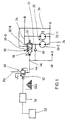
- Fig. 1 is an example of a hydraulic Control circuit for a designated by the reference numeral 20 Radial piston shown, the - schematically indicated - two Piston groups 20-1 and 20-2, of which the engine piston group 20-2 selective for reduction, preferably for halving the Swallowing volume, can be switched off.
- the working pressure or inlet side of the Two-speed radial piston motor 20 is labeled "B", and the drain side with "A".
- the radial piston motor is after the built so-called "multi-stroke principle" in which the radially arranged Support the piston via rollers on a lifting cam.
- the cylinder chambers the individual pistons are controlled via axial bores Supplied pressurized fluid, each piston per shaft revolution so often with Pressure fluid is loaded or unloaded, as is the number of cams on the Lifting curve corresponds.
- the resulting from the shape of the cam ring Torque is preferably provided by a toothing of the Rotor / piston group transferred to an output shaft.
- a valve arrangement in the Design of a continuously adjustable 3/2-way valve 30 which has two end switch positions 30-A and 30-B.
- a return spring 32 pushes the valve body, preferably a spool, in the shown Switching position 30-A, in which the inlet B via line sections 34 and 22nd is switched through to the piston group 20-2.
- the two piston groups 20-2 and 20-1 on an equal footing with hydraulic fluid supplied so that the radial piston motor with a predetermined first Speed and a predetermined first torque works.
- the radial piston motor shown in Fig. 1 is also able to reverse direction of rotation, in which case the connections "A" and "B" are reversed. In this direction of rotation are in the Switching position 30-B of the valve 30, the terminals 22 and 24 of the Piston group 20-2 in turn short-circuited, so this piston group can not contribute to the torque increase. However, these are Connections at working pressure level, so that in this direction of rotation higher energy losses, e.g. Temperature increase of the hydraulic fluid and adjust friction losses.
- the valve 30 is continuous adjustable 3/2-way valve formed, i. as a valve, that between the both end shift positions 30-A and 30-B at least one intermediate shift position has, in the lying in the inlet of the piston group 20-2 Line sections 34 and 22 via an aperture arrangement with each other in Connection stand.
- This intermediate switching position is below Reference to the figures 3ff explained in more detail. The important thing is that Running over this intermediate switching position is used to pressure peaks in the line sections 22, 24 and 34, 36 to smooth and thus uncontrolled torque and / or speed fluctuations to avoid the output shaft of the radial piston engine, which ultimately too a deterioration of the driving behavior of one with such Motor equipped vehicle would lead.
- valve assembly 30 is not the subject of the invention per se, as described in a document under Art. 54 (3) EPC. in the The following is but the generation of the control pressure for the Valve assembly 30 will be described in more detail, since they are in the inventive embodiments of FIGS. 7 to 16 application Can be found.
- the control pressure X is the output pressure of a continuously adjustable Pressure valve 40, with a supply pressure PV preferably by electrical control at the signal terminal 42 set to the value "X" or regulated.
- a branch takes place Control pressure line 44 in a control pressure branch line 48, the other Motors or engine piston groups leads.
- the control of the continuously adjustable pressure valve 40 takes place in the Radial piston engine according to FIG. 1 electrically, by electronic Output signals of a suitable control electronics 50 preferably be given programmatically to the control terminal 42.
- the Control electronics 50 is powered by a voltage source 52, for example powered by a battery.
- the spool of the 3/2-way valve 30 due to the intended driving, i. by suitable control of the drive signal X in a predetermined manner and Mode controlled from one end shift position to the other, i. about the Between-shift position is shifted away, so that pressure changes in the line sections 22, 24, 34 and 36 also controlled and occur in a controlled manner.
- the control can be, for example programmatically so that the path / time diagram of the Movement of the spool as a function of the switching direction (accessory) or shutdown) of the piston group 20-2 varies, which manages the Switching speed at a given smoothing of the pressure peaks too maximize.
- the inventive control provides the valve 30, the possibility of the timing of the control signal on Control terminal 42 to be selected so that it corresponds to the direction of rotation of Radial piston engine is optimally adapted.
- Fig. 2 is a variant of the hydraulic Control circuit for a radial piston motor with two speeds shown.
- those components are which correspond to the components according to FIG. 1, with provided with the same reference numerals but preceded by a "1" is.
- this variant only in the area of Control for the continuously adjustable 3/2-way valve 130 is different.
- the drive pressure X for the valve 130 is at the Variant according to FIG. 2 produced in another way, namely by series connection of a preferably electrically controlled 3/2-way valve 162 and an aperture 164 in a supply pressure PV leading line.
- the 3/2-way valve is in turn by a Control electronics 150 driven in a manner as above has been described with reference to FIG. 1.
- the control the valve arrangement 130 takes place in the variant according to FIG. 2 again such that the valve body of the valve arrangement 130 via its Between-shift position away at a controlled speed movable is.
- FIGS. 2A and 2B show variants for the generation of the Control pressure X shown, with only the detail of the Combination aperture / directional valve is turned off.
- the diaphragm 164 " is in the as 3/3-way valve trained valve 162 "incorporated, in such a way that the diaphragm 164 "in the middle position B comes into operation while in the two other switching positions A and B has no influence.
- the Control of the directional control valve 162 " is made such that the valve spool preferably operated at reduced speed, in particular via the middle shift position is moved away.
- the special advantage the arrangement is that if necessary unrestricted additional Fluid in the control pressure line X can be fed to in this way ensure that over that with respect to the figure 1 closer described anti-cavitation valve 60, 160 hydraulic fluid in Sufficient quantity and be sucked under sufficient pressure can.
- FIG. 2B Another variation of this the danger of cavitation on diminishing facial expression is shown in Figure 2B.
- FIG. 3 is schematically the intermediate switching position 230-Z of the 3/2-way valve 230 indicated. It can be seen that in the intermediate switching position 230-Z the inlet side 222 and the drain side 224th throttled, i. are connected via a diaphragm 231, wherein a another aperture 233 between the supply line 234 and the Supply line 222 throttles the pressure fluid flow to the piston group 220-2. Only in the second end switching position 230-B is the supply line 234 completely blocked, and the inlet 222 and the outlet 224 of the piston group 220-2 unthrottled shorted.
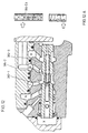
- FIGS. 4A, 5A and 6A each is fragmentary the circuit for those shown in Figures 4B, 5B and 6B Switching position of the valve spool shown.
- the 3/2-way valve 230 is in the switching position 230-A shown.
- a spool 270 is in a bore 272 of a Motor housing 274 in the vicinity of the generally axially extending Distributor bores for controlling the individual radial pistons axially slidably received.
- a spring 232 biases the spool 270 4B to the right against a stop surface 276, which has a Anberichtraum 238 limited, which leads the control pressure "X".
- the spool 270 for a Control pressure X in the range of, for example, 0 to 8 bar occupies the Port B unthrottled to the inlet port 222 of the piston group 220-2 is turned on. In this state, the radial piston motor works 220 - as seen in Fig. 4A - with full torque.
- spool 270 In the spool 270 is a so-called anti-cavitation valve 260 integrated, the structure of which will be described in more detail below.
- the stop surface 276 facing side of the spool has a preferably central recess 277, in which a valve seat body 275 is screwed.
- the valve seat body acts with a valve ball 266 together, recorded with play in a room 268. From the room 268 assumes an axial bore 279, which meets a tap hole 281, which opens into the recess 278 of the spool.
- the geometry and the location of the valve ball 266 is such on geometry and location the axial bore 279 tuned that the valve ball 266 the Axial bore 279 can not close. However, the over the Port B, the tap hole 281 and the axial bore 279 fitting Pressure the valve ball 266 on the valve seat of the valve seat body 275th Press, as long as a corresponding pressure gradient exists.
- the control pressure X in the way and Way is raised to a higher pressure range in which the switching operation expires.
- the spool 270 takes the schematic shown in Fig. 5 Position on ..
- the control pressure X is here sufficiently large to the Spool against the force of spring 232 from the stop surface 276th to lift and according to Fig. 58 to the left to move so far that the Connection from port B to port 222 on the one hand and the Connection from port 222 to port A, i.
- the finely machined and circumferential housing-side Provides control edges, which cooperate with the axial slots 284-B, 284-A.
- this switching state is through the adjustable throttles A1 and A2 indicated, wherein the throttle point A1 the axial slots 284-B and the throttle point A2 corresponds to the axial slots 284-A.
- the Control pressure X preferably programmed and, for example is raised according to a gently rising ramp.
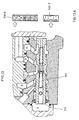
- the Control pressure X a certain upper threshold of, for example, 13th reached bar, takes the 3/2-way valve the second end switching position according to FIG. 6 a.
- the axial slots 284-B have in this switching state, the complementary control edge 286-B for completely over the port B, while the control edge 280 on the side of the terminal A, the connection between the terminal 222 and the port A auf negligencet unthrottled.
- the radial piston motor operates with increased, usually double speed. Because of the lift curve and the rotor however, a permanent mechanical coupling of all pistons of the Radial piston engine is present, the pistons are also deactivated Piston group (s) 220-2 accelerated. So now on the suction side 222 of the Piston group 220-2, the fluid pressure is not below a critical, the occurrence of cavitation causing pressure drops, the anti-cavitation valve, i.e. the check valve 260 in function. As soon as the Pressure in connection 222 should be too low, the ball 266 lifts from Valve seat body 275 from so that hydraulic fluid under the pressure of Control pressure X via the axial bore 279 and the tap hole 281 in the terminal 222 can be fed.
- This mode of operation of the Valve 260 is also particularly important when the radial piston engine in of the high-speed stage shown in FIG. 6 is started.
- the A special feature of the exemplary variant described above is that that the anti-cavitation valve extremely space-saving in the 3/2-way valve 230th is housed.
- Switching the radial piston motor from the high speed stage to the low speed stage is done by corresponding retraction of the control pressure X, again the Path of the spool from one end switch position to the other traversing at a controlled speed.
- the control slots 284-B and 284-A again to used, the occurrence of pressure peaks in the range of up and counteracting zuzuseuuernden connections, which ultimately leads to that the switching process smooth and thus gentle for the individual Components of the radial piston engine takes place.
- the radial piston motor shown in FIG. 7 is in the so-called "4-port configuration" operable, i. he can be both for the full also for half the intake volume in both directions with the same Efficiency can be operated.
- the at the Variants according to Figures 1 to 6 as a continuously adjustable 3/2-way valve trained valve assembly as a continuously adjustable 4/2-way valve 330 configured, the two end switch positions 330-A and 330-B are shown in Fig. 7.
- valve 330 In the end switching position 330-A of the valve 330, the pressure is in the inlet the constantly working engine piston or the constantly working Engine piston group 320-1 to a first connection line 337th through-connected to the inlet 322 of the switched on and off Engine piston (engine piston group) 320-2 leads. At the same time this turns Valve 330 the flow 324 of the engine piston group 320-2 on the second Connecting line 339 to the drain port A through.
- switch position 360-A of the anti-cavitation valve 360 under the influence of a return spring 365 is held against the force at the control terminal 335, is a Branch line 337K closed, although one throttled Drainage is provided at tank pressure level.
- a connection 361 which is connected to the control terminal 335 connected, locked.
- the spool valve 330 closes in the switching position 330-B the connection of the working pressure leading port B to first connection line 337 as well as the connection between the second connection line 339 and the drain port A.
- the first and the second connection line 337, 339 are short-circuited, so that the engine piston group 320-2 no longer contribute to the torque increase can afford. Since in this switching state, the speed of the motor runs up, and the individual pistons 320-1 and 320-2 still are mechanically coupled, the port C or 322 of the piston group 320-2 cavitation hazard.
- the continuously variable directional valve 330 ensures that the Switching from one speed level to the other jerk-free takes place by using intermediate switching positions of the valve 330 and be driven through controlled.
- 8A is a concrete structure of the 4/2-way valve with integrated Anti-cavitation valve 360 described in more detail. For those components that correspond to the components of previous embodiments are again corresponding reference numerals used, which a "3" is preceded.
- valve spool 370 in the bore 372 of a Valve insert 371 received axially displaceable.
- the valve insert 371 is mounted sealed in a distributor part 374, so that the space to the as shown in FIG. 8 right side of the valve spool 370 with a range low pressure in the system, for example, tank pressure is related.
- the valve spool 370 has a stepped bore 373, in whose middle section, a valve body 366 in the form of a cylindrical Slider is recorded accurately and axially movable. Of the Valve body 366 is supported on the right side of FIG. 8 at a Compressing spring 365 from which the valve body 366 in the shown in Fig. 8 Position against a retaining pin 367 presses.
- the Ventifenia 366 has on the the low pressure region side facing a bore 369, in the End several radial-branch channels 369a open, which of a Ring groove 369b go out.
- the valve body 366 acts with a in Control spool 370 formed control bore 381 together, the radial extends to the outside and into a first piston recess 378-1 of the Piston slide 370 opens.
- valve body 366 has on the Blind bore 369 side turned away reduced a section Diameter 366R, so that a piston shoulder 366S is formed. With portion 366R, valve body 366 projects into a portion 373V in FIG Inside of the spool 370, on this page with the Control pressure X is applied.
- the Spool 370 by means of a compression spring 332 in a shown in Fig. 8 Stroke biased position (corresponds to position 330-A of the valve 330 as shown in FIG. 7), in which the left end according to FIG. 8 against a Stop surface 376 is tensioned.
- the stop surface defines a space which is in fluid communication with the drive pressure X.
- Radialausnaturalept shown in the Sim Type of Piston spool 370 is a pressure connection between the space 373V and the space in which the compression spring 332 is received.
- spool 370 receiving bore 372 open Channels corresponding to the respective terminals A, D, C and B (see FIG. 7) to lead.
- a leakage port is labeled LA.
- the Piston recesses 378-1 and 378-2 form control edges 382-1, 382-2 and 382-3, in their area - similar to the design of the Valve 230 of FIGS. 4 to 6 - axial slots 384-1, 384-2 and 384-3 available.
- the connection channels for ports B and D open respectively in a turn 386B and 386D.
- Fig. 9 shows the two valves 330 and 360 in the respective end switching positions 330-A and 360-A.
- Port B is unthrottled over the recess 386B and the piston recess 378-1 with the terminal C, so that the on and off switchable engine piston group 320-2 equal to the piston group 320-1 with working fluid under Working pressure is supplied.
- the respective expiration pages are the Engine piston group 320-1 and 320-2 unthrottled connected by the Port A via the second piston recess 378-2 and the recess 386D is connected to port D.
- the valve body 366 of the anti-cavitation valve 360 occupies a position in which the connection between the terminal C and a Low pressure space or a tank pressure chamber T is blocked by the Valve body 366, the radial channels 381 in the spool 370 closes.
- the valve assembly is so long in the position shown in Fig. 9 held, as the driving pressure X a predetermined first threshold of, for example, 4 bar (equivalent to 58 psi).
- the spool 370 moves against the force of the return spring 332 10 to the right, so that the control edges 382-1 and 382-3 in Function. Due to the axial recesses 384-1 and 384-3 a throttled connection between the terminals B and C. maintained on the one hand and the terminals A and D on the other hand.
- the control pressure X is not in this operating state in the Able to the valve body 366 against the force of the return spring 365 to move so that the anti-cavitation valve in the end switching position 360-A remains.
- the first intermediate switching position of the continuously adjustable 4/2-way valve 330 is designated 330-Z1 in FIG. 10A. These Switching position is for example in a print window between 4 and 7.7 bar (between 58 and 112 psi) held.
- the control edges 382-1 and 382-3 close the connections between B and C on the one hand and between D and A on the other hand completely, so that the continuously adjustable 4/2-way valve 330 has a third intermediate switching position 330-Z3 takes, in which, however, the connection between terminals C and D, i. the short-circuiting of the inlet and outlet side the supply and disconnectable engine piston group 320-2 throttled, because the axial recesses 384-2 are still effective.
- the spool 370 reaches its second end shift position 330-B, which is shown in FIGS. 13, 13A and a stop switching position represents.
- the control pressure X has a in this phase taken sufficiently large value to the valve body 366 in a Intermediate shift position 360-Z (see Fig. 13A) to move.
- this Switch position is briefly a connection of the terminals C and D for Tank side T manufactured to energy losses in the range of in this Operating state shorted and deactivated engine pistons or Keep the engine piston group as small as possible.
- the valve body 366 - Fig. 14 - pushed so far to the right that the shoulder 366S the Radialkanal 381 aufberichtt.
- the terminals C and D with the Drive pressure X connected i. the side to be marked against cavitation the connectable or disconnectable engine piston group 320-2 is reliable with Supplies fluid which is under a sufficiently high pressure, so that the intake pressure in the relevant engine piston a critical Limit does not fall below.
- the anti-cavitation valve 360 thus takes the second end switch position 360-B.
- valves 330 and 360 are equally ensured when the Direction of rotation of the radial piston motor is reversed. It is further Emphasize that by the inventive control of Valves 330 and 360 realized jerk-free and thus the components as far as possible gentle switching between the speeds too is ensured in the case that the radial piston motor in the Switch position of the valves of FIG. 14, i. in the High-speed operation starts and then to operation with half speed and double torque is switched. In this Case, the control pressure X is lowered controlled, so that in turn the switch positions according to FIGS. 14, 13, 12, 11, 10 and 9 taken become.
- FIGS. 8 to 14 is so through a very space-saving design.
- the valve assembly with the continuously adjustable 4/2-way valves 330 and the anti-cavitation valve 360 can be housed with ease in housing parts of the radial piston motor be, with the modular design even the possibility opened, already commercially available radial piston engines with the retrofit valve assembly according to the invention.
- FIGs. 15 and 16 another Embodiment of a control circuit according to the invention shown, in which the protection of the radial piston motor against Cavitation phenomena accomplished in other ways.
- those components which are the components of the embodiment according to the 8 to 14 correspond with similar reference numerals, which, however, is preceded by a "4".
- FIG. 15 is a denoted by 460 Anti-cavitation valve designed as an external 2/2-way valve. It has a Valve slide 466, against the force of a return spring 465 from his Lock position 460-A is displaceable in its passage position 460-B, in the system pressure P to the branch line 437K and thus to the Terminals C and C and D is turned on when the Engine piston group 420-2 in the switch position 430-B of steady 4/2-way valve 430 is disabled and thus the Radial piston engine with increased, i. double speed runs.
- 460 Anti-cavitation valve designed as an external 2/2-way valve. It has a Valve slide 466, against the force of a return spring 465 from his Lock position 460-A is displaceable in its passage position 460-B, in the system pressure P to the branch line 437K and thus to the Terminals C and C and D is turned on when the Engine piston group 420-2 in the switch position 430-B of steady 4/2-way valve 430 is disabled and
- a spool 470 of the steady adjustable 4/2-way valve 430 are carried out in a simplified manner, i. when Solid piston, wherein in an insert body 471, a further connection CK for the coupling of the line coming from the anti-cavitation valve 460 is provided. Otherwise corresponds to the embodiment of the valve according to Fig. 16 that of the embodiment of FIG. 8 to 14, so that on a detailed description can be omitted.
- the embodiments have been based on an application the control circuit according to the invention in a radial piston motor according to described the Mehrhubzin.
- the invention is not limited to this field of application. Rather, the is suitable Control circuit while maintaining the principle of operation of jerk-free Switching speeds for all hydraulic motors where the Switching the speed by selective "neutralizing” and activate Selected Motor Anlagenkammem or working chamber groups takes place.
- This not only enables multi-stroke axial or radial piston motors, but also hydromotors on the planetary gear principle, i. so-called Gerotoren or also various types of piston engines with Stepped piston whose structure roughly explained in the introduction was operated with the control circuit according to the invention.
- the control circuit is also not limited to a Switching between only two Geschwindinkeiten takes place. Much more allows the inventive concept of the control circuit readily Applicable to hydraulic motors containing any number of Have speed levels.
- the invention thus provides, with the features of claim 1, a hydraulic control circuit for a hydraulic motor, in particular a radial piston motor with two speeds, which on extra Space saving way ensures that switching between the speeds smoothly and thus for the individual Building components as gently as possible done.
Description
Ein vergleichbarer, die Gefahr des Auftretens von Kavitation vermindernder Effekt, lässt sich mit der Eingliederung eines Folgeschaltventils nach Anspruch 12 erzielen.
Claims (17)
- Hydraulische Steuerschaltung für einen Hydromotor mit zumindest zwei Geschwindigkeiten, wie z.B. einen mehrhubigen Axial- oder Radialkolbenmotor, einen Hydromotor nach dem Planetenradprinzip oder einen Kolbenmotor mit Stufenkolben, insbesondere für einen Radialkolbenmotor mit zwei Geschwindigkeiten, mit der die Umschaltung zwischen den Geschwindigkeiten durch Veränderung des Schluckvolumens dadurch erfolgt, dass die Schluckvolumina einer ausgewählten Anzahl von Motor-Arbeitskammern (Motorkolben 20-2; 120-2; 220-2; 320-2; 420-2) mittels einer Ventilanordnung (30; 130; 230; 330; 430) selektiv neutralisiert werden, indem für diese Motor-Arbeitskammern die betreffende Zulaufseite (22; 122; 222; C) mit der Ablaufseite (24; 124; 224; 324, D) kurzgeschlossen wird, wobei die Ventilanordnung (30; 130; 230; 330; 430) zwischen den beiden dem betreffenden Umschaltvorgang zugewiesenen Schaltstellungen (30-A, 30-B; 230-A, 230-B; 330-A, 330-B; 430-A, 430-B) zumindest eine Zwischen-Schaltstellung (230-Z; 330-Z2, 330-Z3) hat, in der vorzugsweise unter Androsselung der Strömungsmittelversorgung der zu neutralisierenden Motor-Arbeitskammern (Motorkolbengruppe 20-2; 120-2; 220-2; 320-2; 420-2) die Zulaufseite (22; 122; 222; C) mit der Ablaufseite (24; 124; 224; 324, D) über eine Blendenanordnung (231; A1, A2, 282, 284-A, 284-B, 286-A, 286-B; 382-2, 384-2) verbunden ist, und dass die Ansteuerung der Ventilanordnung (30; 130; 230; 330; 430) derart erfolgt, dass ein Ventilkörper (270; 370, 470) der Ventilanordnung über die Zwischen-Schaltstellung (230-Z; 330-Z1, 330-Z2, 330-Z3) hinweg kontrolliert, vorzugsweise mit gesteuerter Geschwindigkeit bewegbar ist, dadurch gekennzeichnet, dass die Ventilanordnung ein stetig verstellbares 4/2-Wegeventil (330; 430) aufweist, das in seiner einen End-Schaltstellung (Ausgangsschaltstellung 330-A; 430-A) eine Verbindung einerseits zwischen dem Zulauf (A) einer hinsichtlich des Schluckvolumens nicht zu neutralisierenden Motor-Arbeitskammer (Motorkolben 320-1; 420-1) und dem Zulauf (C) der hinsichtlich des Schluckvolumens jeweils zu neutralisierenden Motor-Arbeitskammer (Motorkolben 320-2; 420-2) und andererseits zwischen den jeweiligen Abläufen (B) der Motor-Arbeitskammern bzw. Motorkolben herstellt, und in der anderen End-Schaltstellung (330-B; 430-B) den Zu- und Ablauf (C und D) der zuund abschaltbaren Motor-Arbeitskammer (Motorkolben 320-2; 420-2) kurzschließt und gleichzeitig die übrige Verbindung sperrt.
- Steuerschaltung nach Anspruch 1, dadurch gekennzeichnet, dass die Ventilanordnung ein weiteres Wegeventil (360; 460) aufweist, mit dem in einem Betriebszustand, in dem sich das 4/2-Wegeventil (330; 430) in seiner anderen End-Schaltstellung (330-B; 430-B) befindet, in die Saugseite (C oder D) der hinsichtlich des Schluckvolumens jeweils neutralisierten Motor-Arbeitskammer (Motorkolben 320-2; 420-2) Strömungsmittel einspeisbar ist.
- Steuerschaltung nach Anspruch 2, dadurch gekennzeichnet, dass das weitere Wegeventil von einem stetig verstellbaren 3/2-Wegeventil (360) gebildet ist, das in seiner anderen End-Schaltstellung (360-B) einen Steuerdruck (X) in den Versorgungskreis (Leitung 337K) für die neutralisierte Motor-Arbeitskammer bzw. für den abgeschalteten Motorkolben (320-2) einspeist.
- Steuerschaltung nach einem der Ansprüche 1 bis 3, dadurch gekennzeichnet, dass die Ventilkörper (370, 366) der Wegeventile (330, 360) konzentrisch zueinander angeordnet sind.
- Steuerschaltung nach Anspruch 2, dadurch gekennzeichnet, dass das weitere Wegeventil von einem 2/2-Schaltventil (460) gebildet ist, das in seiner anderen End-Schaltstellung (460-B) Systemdruck (P) in den Versorgungskreis (Leitung 437K) der abgeschalteten Motor-Arbeitskammer bzw. des abgeschalteten Motorkolbens (420-2) einspeist.
- Steuerschaltung nach einem der Ansprüche 2 bis 5, dadurch gekennzeichnet, dass das weitere Wegeventil (360; 460) mit dem Steuerdruck (X) des stetig verstellbaren 4/2-Wegeventils (330; 430) beaufschlagt und angesteuert ist.
- Steuerschaltung nach einem der Ansprüche 1 bis 6, dadurch gekennzeichnet, dass der Ventilkörper (370; 470) des stetig verstellbaren 4/2-Wegeventils (330; 430) ein gegen eine Druckfeder (332) vom Ansteuerdruck (X) beaufschlagter Ventilkolben ist, dessen Steuerkanten (382-1; 382-2; 382-3) mit Nuten (384-1, 384-2, 384-3) ausgestattet sind, die die Blendenanordnung bilden.
- Hydraulische Steuerschaltung nach einem der Ansprüche 1 bis 7 für einen Radialkolbenmotor mit zwei Geschwindigkeiten, wobei die Umschaltung zwischen den Geschwindigkeiten durch Veränderung des Schluckvolumens dadurch erfolgt, dass bei einer ausgewählten Anzahl von Motorkolben (320-2; 420-2) mittels der Ventilanordnung (330; 430) die Zulaufseite (C) mit der Ablaufseite (D) kurzgeschlossen wird, dadurch gekennzeichnet, dass die Ventilanordnung (330; 430) in der Zwischen-Schaltstellung (330-Z2, 330-Z3), in der vorzugsweise eine Androsselung der Strömungsmittelversorgung der Motorkolben der hinsichtlich des Schluckvolumens jeweils zu neutralisierenden Motorkolbengruppe (320-2; 420-2) erfolgt, die Zulaufseite (C) mit der Ablaufseite (D) über eine Blendenanordnung (382-2, 384-2) verbunden ist.
- Steuerschaltung nach einem der Ansprüche 1 bis 8, dadurch gekennzeichnet, dass zur Ansteuerung der Ventilanordnung (330; 430) der Ausgangsdruck (P44, X) eines stetig verstellbaren Druckventils (40) herangezogen wird.
- Steuerschaltung nach einem der Ansprüche 1 bis 9, dadurch gekennzeichnet, dass zur Ansteuerung der Ventilanordnung (330; 430) der Druck (P144, X) in einer Steuerdruckleitung (144) stromab einer Blende (164) herangezogen wird.
- Steuerschaltung nach Anspruch 10, dadurch gekennzeichnet, dass die Blende (164; 164') stromab eines Wegeventils (162) liegt, mit dem die Steuerdruckleitung (144) entweder mit dem Tankdruck (T) oder mit einem Verstärkerdruck (PV) verbindbar ist.
- Steuerschaltung nach Anspruch 11, dadurch gekennzeichnet, dass die Blende (164') mittels eines Folgeschaltventils (165') überbrückbar ist, das oberhalb eines Schwellwerts für den Ansteuerdruck für die Ventilanordnung (130) auf Überbrückung schaltet.
- Steuerschaltung nach Anspruch 10, dadurch gekennzeichnet, dass die Blende (164'') in ein Wegeventil (162'') eingegliedert ist, mit dem die Steuerdruckleitung (144'') entweder zum Tank (T) entlastbar oder mit einem Verstärkerdruck (PV) verbindbar ist, wobei lediglich in einer Mittelstellung (M) des Wegeventils (162'') die Beaufschlagung mit dem Verstärkerdruck (PV) über die Blende (164'') erfolgt.
- Steuerschaltung nach einem der Ansprüche 9 bis 13, dadurch gekennzeichnet, dass der Steuerdruck (X) der Ventilanordnung (330; 430) rampenartig veränderbar ist.
- Steuerschaltung nach einem der Ansprüche 9 bis 13, dadurch gekennzeichnet, dass der Steuerdruck (X) der Ventilanordnung (330; 430) progressiv veränderbar ist.
- Radialkolbenmotor mit einer Steuerschaltung nach einem der Ansprüche 1 bis 15, dadurch gekennzeichnet, dass die Ventilanordnung (330, 360; 430) im Motorgehäuse (374) integriert ist.
- Radialkolbenmotor nach Anspruch 16, dadurch gekennzeichnet, dass die Ventilanordnung als Einsatzmodul (371) ausgebildet ist.
Applications Claiming Priority (5)
| Application Number | Priority Date | Filing Date | Title |
|---|---|---|---|
| DE10007155 | 2000-02-17 | ||
| DE10007155 | 2000-02-17 | ||
| DE10041435A DE10041435A1 (de) | 2000-02-17 | 2000-08-23 | Hydraulische Steuerschaltung für einen Hydromotor mit mindestens zwei Geschwindigkeiten |
| DE10041435 | 2000-08-23 | ||
| PCT/EP2001/001702 WO2001061186A1 (de) | 2000-02-17 | 2001-02-15 | Hydraulische steuerschaltung für einen hydromotor mit mindestens zwei geschwindigkeiten |
Publications (2)
| Publication Number | Publication Date |
|---|---|
| EP1255930A1 EP1255930A1 (de) | 2002-11-13 |
| EP1255930B1 true EP1255930B1 (de) | 2005-06-01 |
Family
ID=26004379
Family Applications (1)
| Application Number | Title | Priority Date | Filing Date |
|---|---|---|---|
| EP01909759A Expired - Lifetime EP1255930B1 (de) | 2000-02-17 | 2001-02-15 | Hydraulische steuerschaltung für einen hydromotor mit mindestens zwei geschwindigkeiten |
Country Status (3)
| Country | Link |
|---|---|
| US (1) | US7090475B2 (de) |
| EP (1) | EP1255930B1 (de) |
| WO (1) | WO2001061186A1 (de) |
Families Citing this family (5)
| Publication number | Priority date | Publication date | Assignee | Title |
|---|---|---|---|---|
| US6679691B1 (en) * | 2002-10-29 | 2004-01-20 | Eaton Corporation | Anti cavitation system for two-speed motors |
| US8444400B2 (en) * | 2009-02-13 | 2013-05-21 | Caterpillar Inc. | Hydraulic cylinder having piston-mounted bypass valve |
| US8851112B2 (en) * | 2012-05-08 | 2014-10-07 | 1566618 Alberta Ltd. | Dual configuration hydraulic manifold apparatus and system |
| DE102014212203A1 (de) | 2014-06-25 | 2015-12-31 | Robert Bosch Gmbh | Hydrostatische Maschinenanordnung |
| DE102017205846A1 (de) * | 2017-04-06 | 2018-10-11 | Robert Bosch Gmbh | Hydraulischer Antrieb für die Vorschubwalzen eines Kopfes eines Holzvollernters |
Family Cites Families (17)
| Publication number | Priority date | Publication date | Assignee | Title |
|---|---|---|---|---|
| DE2514624C3 (de) * | 1975-04-03 | 1986-10-23 | Danfoss A/S, Nordborg | Steuereinrichtung für mindestens einen hydraulisch betriebenen doppeltwirkenden Verbraucher |
| FR2481755A1 (fr) * | 1980-04-30 | 1981-11-06 | Poclain Hydraulics Sa | Moteur a fluide sous pression muni d'un dispositif de selection de sa vitesse de rotation |
| FR2522626A1 (fr) * | 1982-03-02 | 1983-09-09 | Morillon Ets | Dispositif d'assistance au demarrage d'extracteur a vis equipant des cellules de stockage de produits pulverulents ou granuleux |
| US4543786A (en) * | 1983-07-14 | 1985-10-01 | Caterpillar Tractor Co. | Control system for hydrostatic transmission |
| FR2588616B1 (fr) | 1985-10-16 | 1988-01-08 | Poclain Hydraulics Sa | Mecanisme, moteur a pompe, a au moins deux cylindrees actives distinctes. |
| FR2637944B1 (fr) * | 1988-10-19 | 1991-01-25 | Poclain Hydraulics Sa | Mecanisme a fluide sous pression a deux cylindrees et circuit ferme en faisant application |
| FR2673684B1 (fr) * | 1991-03-04 | 1993-07-09 | Poclain Hydraulics Sa | Ensemble d'un moteur a fluide sous pression a plusieurs cylindrees et d'un frein associe. |
| FR2706538B1 (fr) | 1993-06-09 | 1995-09-01 | Poclain Hydraulics Sa | Mécanisme à fluide sous pression tel qu'un moteur ou une pompe, réversible, à au moins deux cylindrées de fonctionnement. |
| JPH082269A (ja) * | 1994-06-21 | 1996-01-09 | Komatsu Ltd | 油圧駆動式走行装置の走行制御回路 |
| JP3127842B2 (ja) | 1996-11-01 | 2001-01-29 | ダイキン工業株式会社 | カムモータ装置 |
| DE69723207T2 (de) * | 1996-11-11 | 2004-04-22 | Denso Corp., Kariya | Bremssteueranlage für Fahrzeuge |
| DE69719999T2 (de) * | 1997-12-02 | 2004-02-19 | Poclain Hydraulics Industrie | Hydraulikmotor mit Schaltventil |
| US6318235B1 (en) * | 1999-06-04 | 2001-11-20 | Poclain Hydraulics Industrie | Hydraulic motor cylinder-capacity selector for avoiding jarring when switching from one cylinder capacity to another |
| FR2794496B1 (fr) | 1999-06-04 | 2001-08-24 | Poclain Hydraulics Ind | Selecteur de cylindree pour un moteur hydraulique evitant un freinage brutal lors du passage de petite cylindree en grande cylindree |
| DE19930425A1 (de) * | 1999-07-01 | 2001-01-04 | Mannesmann Rexroth Ag | Hydrostatischer Fahrantrieb |
| US6422804B1 (en) * | 2000-02-18 | 2002-07-23 | Deere & Company | Inertia load dampening hydraulic system |
| US6609368B2 (en) * | 2001-06-04 | 2003-08-26 | Caterpillar S.A.R.L. | Automatic downshift and override control for a transmission |
-
2001
- 2001-02-15 US US10/203,625 patent/US7090475B2/en not_active Expired - Lifetime
- 2001-02-15 WO PCT/EP2001/001702 patent/WO2001061186A1/de active IP Right Grant
- 2001-02-15 EP EP01909759A patent/EP1255930B1/de not_active Expired - Lifetime
Also Published As
| Publication number | Publication date |
|---|---|
| WO2001061186A1 (de) | 2001-08-23 |
| US20030167770A1 (en) | 2003-09-11 |
| US7090475B2 (en) | 2006-08-15 |
| EP1255930A1 (de) | 2002-11-13 |
Similar Documents
| Publication | Publication Date | Title |
|---|---|---|
| EP1476642B1 (de) | Vorrichtung zur relativen drehwinkelverstellung einer nockenwelle einer brennkraftmaschine zu einem antriebsrad | |
| DE2737788C2 (de) | ||
| EP0335083A1 (de) | Vorrichtung zur relativen Winkelverstellung zwischen zwei in Antriebsverbindung stehenden Wellen | |
| DE60123699T2 (de) | Hydraulische Servolenkung für ein Fahrzeug | |
| DE19580685B4 (de) | Radialkolbenhydraulikmotor und Verfahren zur Regelung eines Radialkolbenhydraulikmotors | |
| DE3913414A1 (de) | Mehrkreis-regelpumpe | |
| DE3142604A1 (de) | Oelpumpeneinheit | |
| EP1255930B1 (de) | Hydraulische steuerschaltung für einen hydromotor mit mindestens zwei geschwindigkeiten | |
| DE3731258A1 (de) | Drehschieberventil fuer hydraulische hilfskraftlenkungen | |
| EP2504534B1 (de) | Vorrichtung zur variablen einstellung der steuerzeiten von gaswechselventilen einer brennkaftmaschine | |
| DE4119333C2 (de) | Hydrostatischer Antrieb mit einem im offenen Kreislauf angeordneten Hydromotor | |
| DE10041435A1 (de) | Hydraulische Steuerschaltung für einen Hydromotor mit mindestens zwei Geschwindigkeiten | |
| DE4409928A1 (de) | Hydraulischer Stellantrieb für die Achslenkung eines Kraftfahrzeuges | |
| DE19804374B4 (de) | Axialkolbenmaschine mit Mitteldrucköffnung | |
| DE4135904A1 (de) | Kolbenpumpe, insbesondere radialkolbenpumpe | |
| DE102007046660A1 (de) | Drehflügelmaschine | |
| DE102017204145A1 (de) | Ölmehrfachpumpe und Kraftfahrzeug mit einer solchen Ölmehrfachpumpe | |
| DE2102019A1 (de) | Druckmittelzumeßpumpe für einen Servomotor | |
| DE20122432U1 (de) | Hydraulische Steuerschaltung für einen Hydromotor mit mindestens zwei Geschwindigkeiten | |
| EP3406837B1 (de) | Hydraulische antriebsbaugruppe für eine fahrzeugtür oder fahrzeugklappe | |
| DE3526319C2 (de) | ||
| DE3145418C2 (de) | ||
| DE3414535C2 (de) | ||
| DE3925298C2 (de) | Hydrostatisches Getriebe | |
| DE2249527A1 (de) | Radialkolbenmaschine |
Legal Events
| Date | Code | Title | Description |
|---|---|---|---|
| PUAI | Public reference made under article 153(3) epc to a published international application that has entered the european phase |
Free format text: ORIGINAL CODE: 0009012 |
|
| 17P | Request for examination filed |
Effective date: 20020813 |
|
| AK | Designated contracting states |
Kind code of ref document: A1 Designated state(s): AT BE CH CY DE DK ES FI FR GB GR IE IT LI LU MC NL PT SE TR |
|
| RAP1 | Party data changed (applicant data changed or rights of an application transferred) |
Owner name: BOSCH REXROTH AG |
|
| RIN1 | Information on inventor provided before grant (corrected) |
Inventor name: SHRIVE, CHRIS |
|
| 17Q | First examination report despatched |
Effective date: 20031107 |
|
| RBV | Designated contracting states (corrected) |
Designated state(s): AT BE CH CY DE FR GB IT LI |
|
| GRAP | Despatch of communication of intention to grant a patent |
Free format text: ORIGINAL CODE: EPIDOSNIGR1 |
|
| RBV | Designated contracting states (corrected) |
Designated state(s): DE FR GB IT |
|
| GRAS | Grant fee paid |
Free format text: ORIGINAL CODE: EPIDOSNIGR3 |
|
| GRAA | (expected) grant |
Free format text: ORIGINAL CODE: 0009210 |
|
| AK | Designated contracting states |
Kind code of ref document: B1 Designated state(s): DE FR GB IT |
|
| REG | Reference to a national code |
Ref country code: GB Ref legal event code: FG4D Free format text: NOT ENGLISH |
|
| REF | Corresponds to: |
Ref document number: 50106387 Country of ref document: DE Date of ref document: 20050707 Kind code of ref document: P |
|
| GBT | Gb: translation of ep patent filed (gb section 77(6)(a)/1977) |
Effective date: 20050902 |
|
| PLBE | No opposition filed within time limit |
Free format text: ORIGINAL CODE: 0009261 |
|
| STAA | Information on the status of an ep patent application or granted ep patent |
Free format text: STATUS: NO OPPOSITION FILED WITHIN TIME LIMIT |
|
| ET | Fr: translation filed | ||
| 26N | No opposition filed |
Effective date: 20060302 |
|
| PGFP | Annual fee paid to national office [announced via postgrant information from national office to epo] |
Ref country code: IT Payment date: 20140224 Year of fee payment: 14 |
|
| PGFP | Annual fee paid to national office [announced via postgrant information from national office to epo] |
Ref country code: GB Payment date: 20140220 Year of fee payment: 14 |
|
| REG | Reference to a national code |
Ref country code: FR Ref legal event code: PLFP Year of fee payment: 15 |
|
| GBPC | Gb: european patent ceased through non-payment of renewal fee |
Effective date: 20150215 |
|
| PG25 | Lapsed in a contracting state [announced via postgrant information from national office to epo] |
Ref country code: IT Free format text: LAPSE BECAUSE OF NON-PAYMENT OF DUE FEES Effective date: 20150215 |
|
| PG25 | Lapsed in a contracting state [announced via postgrant information from national office to epo] |
Ref country code: GB Free format text: LAPSE BECAUSE OF NON-PAYMENT OF DUE FEES Effective date: 20150215 |
|
| REG | Reference to a national code |
Ref country code: FR Ref legal event code: PLFP Year of fee payment: 16 |
|
| REG | Reference to a national code |
Ref country code: FR Ref legal event code: PLFP Year of fee payment: 17 |
|
| PGFP | Annual fee paid to national office [announced via postgrant information from national office to epo] |
Ref country code: FR Payment date: 20170220 Year of fee payment: 17 |
|
| REG | Reference to a national code |
Ref country code: FR Ref legal event code: ST Effective date: 20181031 |
|
| PG25 | Lapsed in a contracting state [announced via postgrant information from national office to epo] |
Ref country code: FR Free format text: LAPSE BECAUSE OF NON-PAYMENT OF DUE FEES Effective date: 20180228 |
|
| PGFP | Annual fee paid to national office [announced via postgrant information from national office to epo] |
Ref country code: DE Payment date: 20200421 Year of fee payment: 20 |
|
| REG | Reference to a national code |
Ref country code: DE Ref legal event code: R071 Ref document number: 50106387 Country of ref document: DE |