EP1254974A1 - Verfahren und Vorrichtung zum Verschieben von auf Kontaktbalken hängenden Metall-Anodenplatten oder Metall-Anodenstäben in Elektrolyttanks - Google Patents
Verfahren und Vorrichtung zum Verschieben von auf Kontaktbalken hängenden Metall-Anodenplatten oder Metall-Anodenstäben in Elektrolyttanks Download PDFInfo
- Publication number
- EP1254974A1 EP1254974A1 EP02009002A EP02009002A EP1254974A1 EP 1254974 A1 EP1254974 A1 EP 1254974A1 EP 02009002 A EP02009002 A EP 02009002A EP 02009002 A EP02009002 A EP 02009002A EP 1254974 A1 EP1254974 A1 EP 1254974A1
- Authority
- EP
- European Patent Office
- Prior art keywords
- anode
- metal anode
- anodes
- strip
- metal
- Prior art date
- Legal status (The legal status is an assumption and is not a legal conclusion. Google has not performed a legal analysis and makes no representation as to the accuracy of the status listed.)
- Granted
Links
- 238000000034 method Methods 0.000 title claims abstract description 9
- 239000002184 metal Substances 0.000 title claims description 29
- 239000011248 coating agent Substances 0.000 claims description 13
- 238000000576 coating method Methods 0.000 claims description 13
- 239000003792 electrolyte Substances 0.000 claims description 8
- 239000000872 buffer Substances 0.000 claims description 4
- 230000001154 acute effect Effects 0.000 claims description 3
- 238000006073 displacement reaction Methods 0.000 abstract description 5
- 239000000725 suspension Substances 0.000 abstract 2
- 238000007747 plating Methods 0.000 abstract 1
- 229910000831 Steel Inorganic materials 0.000 description 4
- 239000010959 steel Substances 0.000 description 4
- 230000002349 favourable effect Effects 0.000 description 3
- 239000007788 liquid Substances 0.000 description 3
- 230000001419 dependent effect Effects 0.000 description 1
Images


Classifications
-
- C—CHEMISTRY; METALLURGY
- C25—ELECTROLYTIC OR ELECTROPHORETIC PROCESSES; APPARATUS THEREFOR
- C25D—PROCESSES FOR THE ELECTROLYTIC OR ELECTROPHORETIC PRODUCTION OF COATINGS; ELECTROFORMING; APPARATUS THEREFOR
- C25D7/00—Electroplating characterised by the article coated
- C25D7/06—Wires; Strips; Foils
- C25D7/0614—Strips or foils
- C25D7/0642—Anodes
Definitions
- the invention relates to a method and an apparatus for moving from Contact bar hanging metal anode plates or metal anode rods in Electrolyte tanks through an anode slide, especially for electrolytic Coil finishing or coating systems.
- metallic tape e.g. Steel strip
- electrolytic Process continuously coated, e.g. tinned.
- the metal anode plates or the metal anode rods using a hook-like tool in the treatment area on both sides of the steel strip to be coated positioned.
- It is known to pack entire anodes by attacking a push rod to be moved mechanically or hydraulically on the last attached outer anode.
- the push rod is connected to a push device that is located approximately at the level of the anode heads and is transportable (DE-OS 23 23 788).
- the actuation of the pushing device i.e. the driving back and forth takes place still by an operator.
- the anodes are also attached still by hand.
- the anodes with the system running at full speed in a short time and without accident or Risk of damaging the belt.
- the anode package sufficiently accurate to the metal strip to be coated align and follow up during coating and e.g. the To change the coating thickness in the band edge area.
- the invention is based, regardless of the replenishment of the task new anode plates or anode rods, whole anode packages faster and position it more precisely.
- the object is achieved according to the invention in that the on the anode bench put on new anodes automatically in the area of the to be coated Band pushed and centered or staggered on both sides positioned in a controlled manner on the belt.
- This allows the entire anode package the number of new, unused anodes compared to the one to be coated Belt moved and moved to the most favorable coating position become.
- the entire anode package thus becomes the one to be coated Band aligned favorably.
- the position of the anode stack is no longer the same Handling dependent on the operator.
- the performance of the system can also be increased by using several Metal anode plates located at the contact bar can be moved simultaneously.
- the posed Object achieved according to the invention in that a beam crossbar is supported on both sides of the bridge bearing and that perpendicular and / or under one acute angle to the tape running direction by means of a drive several on the Metal anodes placed on the contact bar can be moved into the coating position are.
- This allows a controlled positioning of the anodes over the Bandwidth take place and the whole anode package can be adjusted.
- the entire set of anodes can be increased by the number of new, unused ones Anodes shifted in relation to the strip to be coated and in the cheapest Position.
- the beam crossbar is positioned next to one another the treatment tank arranged slidably supported bridge bearings and has rotatably mounted adjusting spindle, at one end of the adjusting spindle a drive motor attacks.
- the drive motor When rotating by the drive motor, the can be operated electrically, hydraulically or pneumatically, the beam crossbar pushed back and forth.
- the adjusting spindle and the pivot bearings and threaded nuts are surrounded by a base frame that even from a front travel frame and a rear travel frame Part lengths is surrounded.
- the adjusting spindle therefore remains in any position surrounded by the base frame and thus protected.
- Another improvement is that one located on the beam crossbar Hook into the rearmost used metal anode using a catch can be snapped into place.
- An increase in performance of the system is achieved in that the beam crossbar interacts with several contact bars running parallel to each other. A shift of the beam crossbar affects everyone on the contact beam metal anodes.
- the adjustment of the beam crossbar can be technically and economically favorable be carried out by using a single drive for the multiple contact bars Beam crossbar is provided.
- the buffers on the beam crossbar are electrically insulated and / or electrically isolated driver pawls are provided.
- the security of the functions can be further increased by the entire Beam crossbar is hung or stored in an electrically insulated manner.
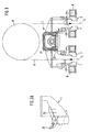
- a beam crossbar 1 is formed, which is arranged at the ends Bridge bearings 2 and 3 is supported.
- the beam crossbar 1 runs vertically and / or at an acute angle to the tape running direction 4 (see FIG. 3) of the metal strip to be coated, in particular steel strip 5.
- the metal strip 5 is led around a current roller 6, so that the metal strip 5 between two rows of anodes (soluble metal anode plates or metal anode rods) continuously transported past becomes.
- the anodes 7 are located on a contact bar 8 and hang from it in an electrolyte tank 9 which is up to the liquid level 10 with electrolyte liquid is filled.
- the metal anodes 7 hang in the coating position 11, i.e. in a distance from the metal strip 5, which is electrolytically favorable.
- the beam crossbar 1 has sliding bearings 12 and 13 with pivot bearings 14 and 17, which together with threaded nuts 15 and 16 by means of an adjusting spindle 18 can be pushed out.
- the beam crossbar 1 forms a front and a rear at the ends Travel frame 19 and 20.
- the left travel frame 19 is in the rest position drawn and the right traversing frame 20 in the change position with a displacement path 21, which depends on the width ratio of the metal strip 5 is so that different widths can be treated.
- the displacement path 21 is carried out by means of a drive 22, which is on the adjusting spindle 18 stores and e.g. can consist of an electric rotary motor 22a.
- the adjusting spindle 18 and the rotary bearings 14 and 17 and the threaded nuts 15 and 16 are surrounded by a base frame 23, which itself is from the front Travel frame 19 and the rear travel frame 20 on the partial lengths shown 24 is surrounded.
- the anode slide 1a is on the front travel frame 19 attached.
- a hook 25 is also attached, which is a driver pawl 26 owns.
- the driver pawl 26 is in the last one or more used metal anodes 7 snap into place and these can then be pulled out become.
- the beam crossbar 1 can have a plurality of contact beams running parallel to one another 8 (as visible in Fig. 3). For several contact bars 8 is the Drive 22 is provided as the only drive that the beam crossbar 1 in total adjusted.
- the beam crossbar 1 On the beam crossbar 1 there are electrically insulated displacement buffers 27 and / or electrically isolated driver pawls 26 are provided. The entire beam crossbar 1 can be hung or stored in an electrically insulated manner his.
Landscapes
- Chemical & Material Sciences (AREA)
- Engineering & Computer Science (AREA)
- Chemical Kinetics & Catalysis (AREA)
- Electrochemistry (AREA)
- Materials Engineering (AREA)
- Metallurgy (AREA)
- Organic Chemistry (AREA)
- Electroplating Methods And Accessories (AREA)
Abstract
Description
- Fig. 1
- xeine Draufsicht auf die Balkentraverse mit Brückenlagern,
- Fig. 2
- einen senkrechten Längsschnitt B-B aus Fig. 1,
- Fig. 2A
- eine Einzelheit C aus Fig. 2 und
- Fig. 3
- einen senkrechten Querschnitt A-A aus Fig. 2.
- 1
- Balkentraverse
- 1a
- Anodenschieber
- 2
- Brückenlager
- 3
- Brückenlager
- 4
- Bandlaufrichtung
- 5
- Metall-, insbesondere Stahlband
- 6
- Stromrolle
- 7
- Metall-Anode
- 8
- Kontaktbalken
- 9
- Elektrolyttank
- 10
- Flüssigkeitsspiegel
- 11
- Beschichtungsposition
- 12
- Schiebelager
- 13
- Schiebelager
- 14
- Drehlager
- 15
- Gewindemutter
- 16
- Gewindemutter
- 17
- Drehlager
- 18
- Verstellspindel
- 19
- vorderer Verfahrrahmen
- 20
- hinterer Verfahrrahmen
- 21
- Verschiebeweg
- 22
- Antrieb
- 22a
- Antriebsmotor
- 23
- Grundrahmen
- 24
- Teillänge
- 25
- Haken
- 26
- elektrisch isolierte Mitnehmerklinke
- 27
- elektrisch isolierter Verschiebepuffer
Claims (11)
- Verfahren zum Verschieben von auf Kontaktbalken hängenden Metall-Anodenplatten oder Metall-Anodenstäben in Elektrolyttanks, durch einen Anodenschieber, insbesondere für elektrolytische Bandveredelungs- oder Beschichtungsanlagen,
dadurch gekennzeichnet, dass die auf die Anodenbank aufgesetzten, neuen Anoden automatisch in den Bereich des zu beschichtenden Bandes geschoben und mittig oder definiert versetzt beidseitig zu dem Band kontrolliert positioniert werden. - Verfahren nach Anspruch 1,
dadurch gekennzeichnet, dass gleichzeitig mit dem Zurückfahren des Anodenschiebers auf der Gegenseite eine oder mehrere, verbrauchte Anoden aus dem Beschichtungsbereich herausgezogen und in eine Wechselposition gefahren werden. - Verfahren nach einem der Ansprüche 1 oder 2,
dadurch gekennzeichnet, dass auf mehreren Kontaktbalken befindliche Metall-Anodenplatten jeweils gleichzeitig verschoben werden. - Vorrichtung für die Verschiebung von auf Kontaktbalken hängenden Metall-Anodenplatten oder Metall-Anodenstäben in Elektrolyttanks mittels eines Anodenschiebers, insbesondere für elektrolytische Bandveredelungs- oder Beschichtungsanlagen,
dadurch gekennzeichnet, dass eine Balkentraverse (1) auf beidseitigen Brückenlagern (2; 3) abgestützt ist und dass senkrecht und / oder unter einem spitzen Winkel zur Bandlaufrichtung (4) mittels eines Antriebs (22) mehrere auf den Kontaktbalken (8) aufgesetzte Metall-Anoden (7) in die Beschichtungsposition (11) verschiebbar sind. - Vorrichtung nach Anspruch 4,
dadurch gekennzeichnet, dass die Balkentraverse (1) eine auf neben dem Elektrolyttank (9) angeordneten Brückenlagern (2; 3) verschiebbar aufgestützte und drehgelagerte Verstellspindel (18) aufweist, wobei an einem Ende der Verstellspindel (18) ein Antriebsmotor (22a) angreift. - Vorrichtung nach einem der Ansprüche 4 oder 5,
dadurch gekennzeichnet, dass die Verstellspindel (18) und die Drehlager (14, 17) sowie Gewindemuttern (15, 16) von einem Grundrahmen (23) umgeben sind, der selbst von einem vorderen Verfahrrahmen (19) und einem hinteren Verfahrrahmen (20) auf Teillängen (24) umgeben ist. - Vorrichtung nach einem der Ansprüche 4 bis 6,
dadurch gekennzeichnet, dass ein an der Balkentraverse (1) angeordneter Haken (25) mittels einer Mitnehmerklinke (26) in die hinterste, verbrauchte Metall-Anode (7) einrastbar ist. - Vorrichtung nach einem der Ansprüche 4 bis 7,
dadurch gekennzeichnet, dass die Balkentraverse (1) mit mehreren, parallel nebeneinander verlaufenden Kontaktbalken (8) zusammenwirkt. - Vorrichtung nach einem der Ansprüche 4 bis 8,
dadurch gekennzeichnet, dass für mehrere Kontaktbalken (8) ein einziger Antrieb (22) für die Balkentraverse (1) vorgesehen ist. - Vorrichtung nach einem der Ansprüche 4 bis 9,
dadurch gekennzeichnet, dass an der Balkentraverse (1) elektrisch isoliert ausgeführte Verschiebepuffer (27) und / oder elektrisch isoliert aufgehängte Mitnehmerklinken (26) vorgesehen sind. - Vorrichtung nach einem der Ansprüche 4 bis 9,
dadurch gekennzeichnet, dass die gesamte Balkentraverse (1) elektrisch isoliert aufgehängt oder gelagert ist.
Applications Claiming Priority (2)
| Application Number | Priority Date | Filing Date | Title |
|---|---|---|---|
| DE10121966A DE10121966A1 (de) | 2001-05-05 | 2001-05-05 | Verfahren und Vorrichtung zum Verschieben von auf Kontaktbalken hängenden Metall-Anodenplatten oder Metall-Anodenstäben in Elektrolyttanks |
| DE10121966 | 2001-05-05 |
Publications (2)
| Publication Number | Publication Date |
|---|---|
| EP1254974A1 true EP1254974A1 (de) | 2002-11-06 |
| EP1254974B1 EP1254974B1 (de) | 2011-12-28 |
Family
ID=7683796
Family Applications (1)
| Application Number | Title | Priority Date | Filing Date |
|---|---|---|---|
| EP02009002A Expired - Lifetime EP1254974B1 (de) | 2001-05-05 | 2002-04-23 | Verfahren und Vorrichtung zum Verschieben von auf Kontaktbalken hängenden Metall-Anodenplatten oder Metall-Anodenstäben in Elektrolyttanks |
Country Status (3)
| Country | Link |
|---|---|
| EP (1) | EP1254974B1 (de) |
| AT (1) | ATE539181T1 (de) |
| DE (1) | DE10121966A1 (de) |
Citations (7)
| Publication number | Priority date | Publication date | Assignee | Title |
|---|---|---|---|---|
| GB551841A (en) * | 1942-02-27 | 1943-03-11 | Carnegie Illinois Steel Corp | Improvement in methods and apparatus for continuously electroplating metallic strips |
| US2399254A (en) * | 1943-05-20 | 1946-04-30 | Nat Steel Corp | Electroplating |
| US2776939A (en) * | 1949-05-05 | 1957-01-08 | Jones & Laughlin Steel Corp | Anode and method of continuous plating |
| GB2093863A (en) * | 1981-02-24 | 1982-09-08 | Nippon Kokan Kk | Method for electroplating steel strip and electroplating apparatus |
| WO1990002219A1 (en) * | 1988-08-18 | 1990-03-08 | Techint Compagnia Tecnica Internazionale S.P.A. | A horizontal electrolytic metallization cell plant with soluble anodes, for the continuous electrolytic treatment of steel strips on one or two faces, and process |
| JPH02259100A (ja) * | 1989-03-31 | 1990-10-19 | Kawasaki Steel Corp | ストリップのラジアルセル型めっき装置 |
| US6024846A (en) * | 1997-07-02 | 2000-02-15 | Kvaerner Metals Clecim | Installation for electrolytic coating of metallic bands and anode for such an installation |
-
2001
- 2001-05-05 DE DE10121966A patent/DE10121966A1/de not_active Withdrawn
-
2002
- 2002-04-23 EP EP02009002A patent/EP1254974B1/de not_active Expired - Lifetime
- 2002-04-23 AT AT02009002T patent/ATE539181T1/de active
Patent Citations (7)
| Publication number | Priority date | Publication date | Assignee | Title |
|---|---|---|---|---|
| GB551841A (en) * | 1942-02-27 | 1943-03-11 | Carnegie Illinois Steel Corp | Improvement in methods and apparatus for continuously electroplating metallic strips |
| US2399254A (en) * | 1943-05-20 | 1946-04-30 | Nat Steel Corp | Electroplating |
| US2776939A (en) * | 1949-05-05 | 1957-01-08 | Jones & Laughlin Steel Corp | Anode and method of continuous plating |
| GB2093863A (en) * | 1981-02-24 | 1982-09-08 | Nippon Kokan Kk | Method for electroplating steel strip and electroplating apparatus |
| WO1990002219A1 (en) * | 1988-08-18 | 1990-03-08 | Techint Compagnia Tecnica Internazionale S.P.A. | A horizontal electrolytic metallization cell plant with soluble anodes, for the continuous electrolytic treatment of steel strips on one or two faces, and process |
| JPH02259100A (ja) * | 1989-03-31 | 1990-10-19 | Kawasaki Steel Corp | ストリップのラジアルセル型めっき装置 |
| US6024846A (en) * | 1997-07-02 | 2000-02-15 | Kvaerner Metals Clecim | Installation for electrolytic coating of metallic bands and anode for such an installation |
Non-Patent Citations (1)
| Title |
|---|
| PATENT ABSTRACTS OF JAPAN vol. 015, no. 012 (C - 0795) 10 January 1991 (1991-01-10) * |
Also Published As
| Publication number | Publication date |
|---|---|
| EP1254974B1 (de) | 2011-12-28 |
| ATE539181T1 (de) | 2012-01-15 |
| DE10121966A1 (de) | 2002-11-07 |
Similar Documents
| Publication | Publication Date | Title |
|---|---|---|
| DE4410477C1 (de) | Vorrichtung zur Oberflächenbehandlung von Fahrzeugkarosserien | |
| AT400934B (de) | Verfahren und anlage zum zuführen von längselementen aus rund- oder flachmaterial zu einer durchlauf-schweissmaschine für gitter oder gitterroste | |
| DE3307890C2 (de) | Verfahren und Vorrichtung zum Reinigen von bei der elektrolytischen Raffination von Metallen gewonnenen Kathodenplatten, insbesondere Cu-Kathodenplatten | |
| DE2635194C2 (de) | Zuführvorrichtung für zu bedruckendes Gut | |
| DE2623938A1 (de) | Vorrichtung zum auswechseln der elektroden fuer die elektrische raffination von metallen | |
| DE3141784C2 (de) | Vorrichtung zum Zu- und Wegführen von Statoren elektrischer Maschinen | |
| WO2008155392A1 (de) | Sägevorrichtung und verfahren zur sägenden bearbeitung eines werkstücks | |
| EP0278308A2 (de) | Anordnung zur Beschickung von Traggestellen in Anlagen zum chemischen Behandeln in Bädern, insbesondere zum Galvanisieren von plattenförmigen Gegenständen | |
| DE69417648T2 (de) | Vorrichtung zum Wiederfinden und Entladen von kurzen Stangen | |
| EP0422578B1 (de) | Einrichtung zum Verlegen von Schwellen | |
| EP0453806A1 (de) | Einrichtung zum Abstapeln von aus aufgeteilten, plattenförmigen Einzelwerkstücken oder Plattenpaketen hergestellten Einzelformaten | |
| DE2534263C2 (de) | Selbsttätige Einrichtung zum kontinuierlichen Zuführen von gestapelten Gegenständen | |
| DE9218147U1 (de) | Flexibles Transportsystem | |
| DE3306849C2 (de) | Galvanisieranlage zum selektiren Beschichten einer Folge von Werkstücken | |
| DE2106091B2 (de) | Vorrichtung zum verschachtelten, lageweisen Stapeln von profiliertem Walzgut | |
| EP1254974B1 (de) | Verfahren und Vorrichtung zum Verschieben von auf Kontaktbalken hängenden Metall-Anodenplatten oder Metall-Anodenstäben in Elektrolyttanks | |
| DE2547114C2 (de) | ||
| EP0798238B1 (de) | Lagersystem für Langgutpaletten | |
| EP0034578B2 (de) | Vorrichtung zum Führen der einzelnen Streifen eines in Längsstreifen geteilten Blechbandes | |
| DE3310058C2 (de) | ||
| DE2839532B2 (de) | Wagen zum Fördern und Zuführen von gestapelten Platten zu den Maschinen für die Bearbeitung von gedruckten Schaltungen | |
| DE3117464A1 (de) | Einrichtung zum entnehmen von walzstaeben aus einer stablage | |
| DE2323788C3 (de) | Vorrichtung zum Verschieben von mehreren hängenden Metallanoden auf Stromschienen in Elektrolyttanks von elektrolytischen Bandveredelungs-, insbesondere Verzinnungsanlagen | |
| DE4314600B4 (de) | Vorrichtung zur lageweisen Stapelung von gruppierten Gegenständen | |
| DE3888879T2 (de) | Automatische Vorrichtung zur kontinuierlichen galvanischen Behandlung von Metallstäben. |
Legal Events
| Date | Code | Title | Description |
|---|---|---|---|
| PUAI | Public reference made under article 153(3) epc to a published international application that has entered the european phase |
Free format text: ORIGINAL CODE: 0009012 |
|
| 17P | Request for examination filed |
Effective date: 20020423 |
|
| AK | Designated contracting states |
Kind code of ref document: A1 Designated state(s): AT BE CH CY DE DK ES FI FR GB GR IE IT LI LU MC NL PT SE TR |
|
| AX | Request for extension of the european patent |
Free format text: AL;LT;LV;MK;RO;SI |
|
| AKX | Designation fees paid |
Designated state(s): AT BE CH CY DE DK ES FI FR GB GR IE IT LI LU MC NL PT SE TR |
|
| 17Q | First examination report despatched |
Effective date: 20040618 |
|
| 17Q | First examination report despatched |
Effective date: 20040618 |
|
| RAP1 | Party data changed (applicant data changed or rights of an application transferred) |
Owner name: SMS SIEMAG AG |
|
| GRAP | Despatch of communication of intention to grant a patent |
Free format text: ORIGINAL CODE: EPIDOSNIGR1 |
|
| GRAS | Grant fee paid |
Free format text: ORIGINAL CODE: EPIDOSNIGR3 |
|
| GRAA | (expected) grant |
Free format text: ORIGINAL CODE: 0009210 |
|
| AK | Designated contracting states |
Kind code of ref document: B1 Designated state(s): AT BE CH CY DE DK ES FI FR GB GR IE IT LI LU MC NL PT SE TR |
|
| REG | Reference to a national code |
Ref country code: GB Ref legal event code: FG4D Free format text: NOT ENGLISH |
|
| REG | Reference to a national code |
Ref country code: CH Ref legal event code: EP |
|
| REG | Reference to a national code |
Ref country code: AT Ref legal event code: REF Ref document number: 539181 Country of ref document: AT Kind code of ref document: T Effective date: 20120115 |
|
| REG | Reference to a national code |
Ref country code: IE Ref legal event code: FG4D |
|
| REG | Reference to a national code |
Ref country code: DE Ref legal event code: R096 Ref document number: 50215326 Country of ref document: DE Effective date: 20120301 |
|
| REG | Reference to a national code |
Ref country code: NL Ref legal event code: VDEP Effective date: 20111228 |
|
| PG25 | Lapsed in a contracting state [announced via postgrant information from national office to epo] |
Ref country code: GR Free format text: LAPSE BECAUSE OF FAILURE TO SUBMIT A TRANSLATION OF THE DESCRIPTION OR TO PAY THE FEE WITHIN THE PRESCRIBED TIME-LIMIT Effective date: 20120329 Ref country code: SE Free format text: LAPSE BECAUSE OF FAILURE TO SUBMIT A TRANSLATION OF THE DESCRIPTION OR TO PAY THE FEE WITHIN THE PRESCRIBED TIME-LIMIT Effective date: 20111228 |
|
| PG25 | Lapsed in a contracting state [announced via postgrant information from national office to epo] |
Ref country code: CY Free format text: LAPSE BECAUSE OF FAILURE TO SUBMIT A TRANSLATION OF THE DESCRIPTION OR TO PAY THE FEE WITHIN THE PRESCRIBED TIME-LIMIT Effective date: 20111228 |
|
| REG | Reference to a national code |
Ref country code: IE Ref legal event code: FD4D |
|
| PG25 | Lapsed in a contracting state [announced via postgrant information from national office to epo] |
Ref country code: IE Free format text: LAPSE BECAUSE OF FAILURE TO SUBMIT A TRANSLATION OF THE DESCRIPTION OR TO PAY THE FEE WITHIN THE PRESCRIBED TIME-LIMIT Effective date: 20111228 Ref country code: NL Free format text: LAPSE BECAUSE OF FAILURE TO SUBMIT A TRANSLATION OF THE DESCRIPTION OR TO PAY THE FEE WITHIN THE PRESCRIBED TIME-LIMIT Effective date: 20111228 |
|
| PGFP | Annual fee paid to national office [announced via postgrant information from national office to epo] |
Ref country code: DE Payment date: 20120420 Year of fee payment: 11 |
|
| PG25 | Lapsed in a contracting state [announced via postgrant information from national office to epo] |
Ref country code: PT Free format text: LAPSE BECAUSE OF FAILURE TO SUBMIT A TRANSLATION OF THE DESCRIPTION OR TO PAY THE FEE WITHIN THE PRESCRIBED TIME-LIMIT Effective date: 20120430 |
|
| PGFP | Annual fee paid to national office [announced via postgrant information from national office to epo] |
Ref country code: IT Payment date: 20120423 Year of fee payment: 11 |
|
| BERE | Be: lapsed |
Owner name: SMS SIEMAG AG Effective date: 20120430 |
|
| PG25 | Lapsed in a contracting state [announced via postgrant information from national office to epo] |
Ref country code: DK Free format text: LAPSE BECAUSE OF FAILURE TO SUBMIT A TRANSLATION OF THE DESCRIPTION OR TO PAY THE FEE WITHIN THE PRESCRIBED TIME-LIMIT Effective date: 20111228 |
|
| PLBE | No opposition filed within time limit |
Free format text: ORIGINAL CODE: 0009261 |
|
| STAA | Information on the status of an ep patent application or granted ep patent |
Free format text: STATUS: NO OPPOSITION FILED WITHIN TIME LIMIT |
|
| PG25 | Lapsed in a contracting state [announced via postgrant information from national office to epo] |
Ref country code: MC Free format text: LAPSE BECAUSE OF NON-PAYMENT OF DUE FEES Effective date: 20120430 |
|
| REG | Reference to a national code |
Ref country code: CH Ref legal event code: PL |
|
| 26N | No opposition filed |
Effective date: 20121001 |
|
| GBPC | Gb: european patent ceased through non-payment of renewal fee |
Effective date: 20120423 |
|
| REG | Reference to a national code |
Ref country code: FR Ref legal event code: ST Effective date: 20121228 |
|
| REG | Reference to a national code |
Ref country code: DE Ref legal event code: R097 Ref document number: 50215326 Country of ref document: DE Effective date: 20121001 |
|
| PG25 | Lapsed in a contracting state [announced via postgrant information from national office to epo] |
Ref country code: GB Free format text: LAPSE BECAUSE OF NON-PAYMENT OF DUE FEES Effective date: 20120423 Ref country code: LI Free format text: LAPSE BECAUSE OF NON-PAYMENT OF DUE FEES Effective date: 20120430 Ref country code: CH Free format text: LAPSE BECAUSE OF NON-PAYMENT OF DUE FEES Effective date: 20120430 Ref country code: BE Free format text: LAPSE BECAUSE OF NON-PAYMENT OF DUE FEES Effective date: 20120430 |
|
| PG25 | Lapsed in a contracting state [announced via postgrant information from national office to epo] |
Ref country code: FR Free format text: LAPSE BECAUSE OF NON-PAYMENT OF DUE FEES Effective date: 20120430 |
|
| PGFP | Annual fee paid to national office [announced via postgrant information from national office to epo] |
Ref country code: AT Payment date: 20120411 Year of fee payment: 11 |
|
| PG25 | Lapsed in a contracting state [announced via postgrant information from national office to epo] |
Ref country code: ES Free format text: LAPSE BECAUSE OF FAILURE TO SUBMIT A TRANSLATION OF THE DESCRIPTION OR TO PAY THE FEE WITHIN THE PRESCRIBED TIME-LIMIT Effective date: 20120408 |
|
| PG25 | Lapsed in a contracting state [announced via postgrant information from national office to epo] |
Ref country code: FI Free format text: LAPSE BECAUSE OF FAILURE TO SUBMIT A TRANSLATION OF THE DESCRIPTION OR TO PAY THE FEE WITHIN THE PRESCRIBED TIME-LIMIT Effective date: 20111228 |
|
| REG | Reference to a national code |
Ref country code: AT Ref legal event code: MM01 Ref document number: 539181 Country of ref document: AT Kind code of ref document: T Effective date: 20130430 |
|
| PG25 | Lapsed in a contracting state [announced via postgrant information from national office to epo] |
Ref country code: DE Free format text: LAPSE BECAUSE OF NON-PAYMENT OF DUE FEES Effective date: 20131101 Ref country code: AT Free format text: LAPSE BECAUSE OF NON-PAYMENT OF DUE FEES Effective date: 20130430 |
|
| REG | Reference to a national code |
Ref country code: DE Ref legal event code: R119 Ref document number: 50215326 Country of ref document: DE Effective date: 20131101 |
|
| PG25 | Lapsed in a contracting state [announced via postgrant information from national office to epo] |
Ref country code: IT Free format text: LAPSE BECAUSE OF NON-PAYMENT OF DUE FEES Effective date: 20130423 |
|
| PG25 | Lapsed in a contracting state [announced via postgrant information from national office to epo] |
Ref country code: TR Free format text: LAPSE BECAUSE OF FAILURE TO SUBMIT A TRANSLATION OF THE DESCRIPTION OR TO PAY THE FEE WITHIN THE PRESCRIBED TIME-LIMIT Effective date: 20111228 |
|
| PG25 | Lapsed in a contracting state [announced via postgrant information from national office to epo] |
Ref country code: LU Free format text: LAPSE BECAUSE OF NON-PAYMENT OF DUE FEES Effective date: 20120423 |