EP1254404B1 - Thermostatventil für sanitärarmaturen - Google Patents
Thermostatventil für sanitärarmaturen Download PDFInfo
- Publication number
- EP1254404B1 EP1254404B1 EP01927663A EP01927663A EP1254404B1 EP 1254404 B1 EP1254404 B1 EP 1254404B1 EP 01927663 A EP01927663 A EP 01927663A EP 01927663 A EP01927663 A EP 01927663A EP 1254404 B1 EP1254404 B1 EP 1254404B1
- Authority
- EP
- European Patent Office
- Prior art keywords
- valves
- thermostatic valve
- valve according
- expansion element
- mixing chamber
- Prior art date
- Legal status (The legal status is an assumption and is not a legal conclusion. Google has not performed a legal analysis and makes no representation as to the accuracy of the status listed.)
- Expired - Lifetime
Links
- XLYOFNOQVPJJNP-UHFFFAOYSA-N water Substances O XLYOFNOQVPJJNP-UHFFFAOYSA-N 0.000 claims abstract description 45
- 239000000463 material Substances 0.000 claims abstract description 8
- 239000002184 metal Substances 0.000 claims description 2
- 239000011324 bead Substances 0.000 description 6
- 238000011161 development Methods 0.000 description 4
- 230000018109 developmental process Effects 0.000 description 4
- 230000006835 compression Effects 0.000 description 1
- 238000007906 compression Methods 0.000 description 1
- 230000001419 dependent effect Effects 0.000 description 1
- 230000000694 effects Effects 0.000 description 1
- 230000001105 regulatory effect Effects 0.000 description 1
Images

Classifications
-
- G—PHYSICS
- G05—CONTROLLING; REGULATING
- G05D—SYSTEMS FOR CONTROLLING OR REGULATING NON-ELECTRIC VARIABLES
- G05D23/00—Control of temperature
- G05D23/01—Control of temperature without auxiliary power
- G05D23/13—Control of temperature without auxiliary power by varying the mixing ratio of two fluids having different temperatures
- G05D23/1306—Control of temperature without auxiliary power by varying the mixing ratio of two fluids having different temperatures for liquids
- G05D23/132—Control of temperature without auxiliary power by varying the mixing ratio of two fluids having different temperatures for liquids with temperature sensing element
- G05D23/134—Control of temperature without auxiliary power by varying the mixing ratio of two fluids having different temperatures for liquids with temperature sensing element measuring the temperature of mixed fluid
- G05D23/1346—Control of temperature without auxiliary power by varying the mixing ratio of two fluids having different temperatures for liquids with temperature sensing element measuring the temperature of mixed fluid with manual temperature setting means
- G05D23/1353—Control of temperature without auxiliary power by varying the mixing ratio of two fluids having different temperatures for liquids with temperature sensing element measuring the temperature of mixed fluid with manual temperature setting means combined with flow controlling means
Definitions
- thermostatic valves are known in the sanitary sector, in other words, valves in which one has been set Temperature of the mixed water is regulated by the valve.
- Such sanitary fittings have an actuator to Set the amount of mixed water flowing out, as well as a another actuator with which the target temperature of the Mixed water is set.
- Thermostatic valves are usually designed so that they contain an expansion element, the temperature of the Mixed water is exposed and when this temperature changes a closing body that moves simultaneously for two Inlet valves form the closing body.
- the inlet opening for the cold water and the inlet opening for the warm one Water is considered to be a narrow one extending along a circumference Slits formed, with a cylindrical ring area as Closing body is used. This ring body must go to the outside be sealed off. When moving in the axial direction to change the cross-section of both inlet openings the seal is pushed over a surface. That through the Inlet water flowing must be axially out of the mixing room flow out, so that the currents of both Lead the inlet openings in the same direction.
- the closing element must be a ring with water flowing through it.
- An example of such a thermostat is DE 19716307 A1.
- a mixer tap with automatic control of the outflowing water (DE 1 206 241), with an outlet from the fitting is arranged between the two inlets in the fitting.
- the cold and warm Water enters the mixing chamber in the same direction.
- thermostatically controlled mixer tap (DE 24 48 485 A1), in which the cold and warm water through an annular gap in an imaginary cylindrical surface emerge radially in the same direction into a mixing chamber.
- the invention has for its object a thermostatic valve to improve its function for sanitary fittings.
- the invention proposes a thermostatic valve with the features of claim 1. Further developments the invention are the subject of the dependent claims, their wording as well as the wording of the summary by reference to the content of the description is made.
- the thermostatic valve according to the invention the outlet arranged so that it lies between the two inlet valves. It occurs through it an equalization of the temperature by an improved Mix the cold and warm water. Furthermore according to the invention, it becomes possible to seal the closing body, that tends to save.
- the expansion element With the expansion element, the temperature of the mixed water exposed, it can be an advantage act mechanically working element, for example a Bi-metal element or one with such thermostats usual expansion element.
- valve seat be at least one of the two valves, preferably both valves, from one in substantially flat annular surface is formed, which is advantageous bounded by an opening formed by the edge of the valve seat. The water flows into the mixing room through this opening.
- the ring surfaces of both valves in mutually parallel planes are arranged, the end faces in a development of the invention of the mixing room.
- the movement of the two Capping body, which takes place simultaneously, can therefore be a be axial movement in the mixing room.
- the closing body can be plate-shaped.
- the Expansion element with the closing bodies of both valve seats forms a structural unit. This can be done, for example be realized that the closing elements for both Valve seats are or are part of the expansion element form this expansion element.
- the water flows through both valves in the opposite direction into the mixing room to be led. This leads to a particularly effective mixing the water flow and thus to achieve a uniform mixing temperature of the expansion element can then be subjected.
- the thermostatic valve contains a fitting body 1, which is an elongated has a slightly spherical shape.
- a handle 2 for volume control of the thermostatic valve leaving mixed water arranged. He can do that Longitudinal axis of the valve can be rotated.
- a handle 3 is arranged with which the target temperature of the mixed water can be adjusted.
- An inlet 4 for radially leads into the valve housing 1 warm water and, also radial, an inlet 5 for cold Water. Both inlets, for example via hoses can be realized, open into radial holes that each in a cylindrical space 18, 20 within the Valve body 1 open.
- valve body 1 is approximately cylindrical in the middle formed coaxially to the base body 13, the serves to hold a valve.
- the control unit 15 contains an expansion element, that responds to temperature changes and reacts.
- the control unit contains one axial end in the area a closure element 17 connected to it, which in the embodiment shown the shape of a flat disc having.
- On its end facing the chamber 13 Side contains the closing element 17 a circumferential concentric bead, which cooperates with the shoulder 6, which surrounds the opening 18.
- the closing element 17 forms together with the shoulder 16 a valve.
- the opening 18 surrounding edge region of the shoulder 16 thus forms a Valve seat.
- the bead 7 on the has the side facing the room 20.
- This closing element too 19 is designed as a flat disc.
- the Bead 7 interacts with shoulder 6, which defines opening 20 surrounds.
- a valve with a valve seat is also formed here.
- the distance between the two closing elements 17, 19 from each other is chosen so that the axial distance of the outside of the Bead 7 is smaller than the distance between the shoulders 6. This means that one of the two valves is always open.
- Both closing elements 17, 19 contain radially outside of the bead 7 extending in the axial direction or Breakthroughs 8.
- the closing bodies 17, 19 are sufficient up to the jacket of the cylindrical space 13. Guide the control unit 15.
- a material is arranged in the expansion element 16, that expands when the temperature rises. If that Expands material inside the expansion element 16, so it moves this with the two closing elements 17, 19 left in the figures. This happens against the Effect of a control spring 24. Reduced in this shift the flow cross section of the through the openings 18th and the closing body 17 formed valve. simultaneously The distance increases on the opposite side between the closing body 19 and the edge of the opening 20. In this way the ratio of flow cross section of the warm water to the flow cross section of the cold Water changed.
- This room is referred to here as the mixing room.
- the expansion element 16 is the temperature of the in this Exposed mixed water exposed. It therefore regulates the Opening cross sections of the two valves depending on the temperature of the mixed water.
- the outlet from this room in the direction of that in FIGS. 1 and 2 downward arrow is at a point that spatially and in the direction of movement of the closing body seen between the two valves.
- the two Currents flow towards each other in the mixing room 13, so that they mix very well and quickly there.
- the expansion element 16 therefore has the relatively quickly Temperature of the mixed water.
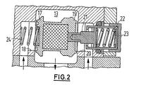
- FIG. 2 schematically shows one on an enlarged scale second embodiment, in which also the expansion element 16 seen in the direction of movement between the two Inlet valves is arranged.
- the expansion element is formed as a structural unit, the in the region of its one axial end, the closing element 17 and the closing element in the region of its opposite end 19 forms.
- Both closing elements are designed in this way or dimensioned that they are not in the radial direction lead to the edge of the interior 13 in which the Water mixed. The warm and cold water flows with the valve open on the closing elements 17, 19 past.
- a space is formed inside the expansion element, in the material that responds to temperature changes is filled.
- the wall thickness of the expansion element is on the end faces significantly larger than on the coat, so that in the room 13 existing mixed water inside the expansion of the element mainly determined.
- the compression spring 23 forming an overload spring is here between the inner face of the outer plunger 22 and the outer end face of the inner plunger 21.
Landscapes
- Physics & Mathematics (AREA)
- General Physics & Mathematics (AREA)
- Engineering & Computer Science (AREA)
- Automation & Control Theory (AREA)
- Temperature-Responsive Valves (AREA)
- Multiple-Way Valves (AREA)
- Door And Window Frames Mounted To Openings (AREA)
- Soil Working Implements (AREA)
Description
- Fig. 1
- Figur 1 einen Längsschnitt durch ein Thermostatventil nach der vorliegenden Erfindung;
- Fig. 2
- in einem gegenüber der Figur 1 vergrößerten Maßstab eine schematische Darstellung der Wirkungsweise des Thermostatventils.
Claims (11)
- Thermostatventil für Sanitärarmaturen, mit1.1 einem in einen Mischraum (13) führenden Einlassventil für kaltes Wasser,1.2 einem in dem Mischraum (13) führenden Einlassventil für warmes Wasser,1.3 die jeweils einen Ventilsitz und ein Verschließelement (17, 19) aufweisen,1.4 einem in dem Mischraum (13) angeordneten und der Temperatur des Mischwassers ausgesetzten Ausdehnungselement (16), das1.4.1 mit beiden Verschließelementen (17, 19) wirkverbunden ist und1.4.2 diese bei Temperaturänderungen gemeinsam zur Steuerung beider Ventile bewegt, sowie mit1.5 einem Auslass für das Mischwasser, der1.5.1 zwischen den beiden Ventilen angeordnet ist, dadurch gekennzeichnet, dass die beiden Strömungen gegeneinander gerichtet in den Mischraum (13) gelangen.
- Thermostatventil nach Anspruch 1, bei dem der Ventilsitz mindestens eines der beiden Ventile von einer im wesentlichen ebenen Ringfläche gebildet ist.
- Thermostatventil nach Anspruch 1 oder 2, bei dem der Ventilsitz beider Ventile von einer im wesentlichen ebenen Ringfläche gebildet ist.
- Thermostatventil nach einem der vorhergehenden Ansprüche, bei dem die Ebenen, in denen die Ventilsitze beider Ventile angeordnet sind, parallel zueinander verlaufen.
- Thermostatventil nach einem der vorhergehenden Ansprüche, bei dem die Ebenen, in denen die Ventilsitze beider Ventile angeordnet sind, Stirnflächen des Mischraums (13) bilden.
- Thermostatventil nach einem der vorhergehenden Ansprüche, bei dem das Ausdehnungselement (16) mit den Verschließelementen (17, 19) beider Ventile eine Baueinheit bildet.
- Thermostatventil nach einem der vorhergehenden Ansprüche, bei dem die Verschließelemente (17, 19) beider Ventile einen Teil des Dehnstoffelementes (16) bilden.
- Thermostatventil nach einem der vorhergehenden Ansprüche, bei dem das Wasser durch beide Ventile gegenläufig und vorzugsweise axial in den Mischraum (13) geführt wird und aus diesem insbesondere radial entnommen wird.
- Thermostatventil nach einem der vorhergehenden Ansprüche, bei dem das Ausdehnungselement ein Dehnstoffelement enthält.
- Thermostatventil nach einem der Ansprüche 1 bis 8, bei dem das Ausdehnungselement (16) ein Bi-Metallelement aufweist.
- Thermostatventil nach einem der Ansprüche 1 bis 8, bei dem das Ausdehnungselement ein Element aus Memory-Metall aufweist.
Applications Claiming Priority (3)
| Application Number | Priority Date | Filing Date | Title |
|---|---|---|---|
| DE10006374A DE10006374A1 (de) | 2000-02-12 | 2000-02-12 | Thermostatventil für Sanitärarmaturen |
| DE10006374 | 2000-02-12 | ||
| PCT/EP2001/001489 WO2001059538A2 (de) | 2000-02-12 | 2001-02-10 | Thermostatventil für sanitärarmaturen |
Publications (2)
| Publication Number | Publication Date |
|---|---|
| EP1254404A2 EP1254404A2 (de) | 2002-11-06 |
| EP1254404B1 true EP1254404B1 (de) | 2003-08-20 |
Family
ID=7630771
Family Applications (1)
| Application Number | Title | Priority Date | Filing Date |
|---|---|---|---|
| EP01927663A Expired - Lifetime EP1254404B1 (de) | 2000-02-12 | 2001-02-10 | Thermostatventil für sanitärarmaturen |
Country Status (9)
| Country | Link |
|---|---|
| US (1) | US20040016816A1 (de) |
| EP (1) | EP1254404B1 (de) |
| JP (1) | JP2003522917A (de) |
| CN (1) | CN1236368C (de) |
| AT (1) | ATE247844T1 (de) |
| AU (1) | AU5463701A (de) |
| DE (2) | DE10006374A1 (de) |
| ES (1) | ES2202288T3 (de) |
| WO (1) | WO2001059538A2 (de) |
Families Citing this family (13)
| Publication number | Priority date | Publication date | Assignee | Title |
|---|---|---|---|---|
| DE102004012782B4 (de) * | 2004-03-15 | 2007-04-05 | Kludi Gmbh & Co. Kg | Thermostatventil |
| DE602006019648D1 (de) * | 2005-05-09 | 2011-02-24 | Kohler Co | Temperaturregeleinrichtung für ein Mischventil |
| SE529727C2 (sv) * | 2006-03-17 | 2007-11-06 | Gustavsberg Ab | Vätskereglage |
| GB0900866D0 (en) * | 2009-01-17 | 2009-03-04 | Furlong David J | Thermostatic energy/water/time saving device for instant water heating devices |
| US9915959B2 (en) * | 2012-02-23 | 2018-03-13 | GM Global Technology Operations LLC | Diesel fuel temperature relief valve |
| US9340958B2 (en) * | 2012-06-22 | 2016-05-17 | Kohler Mira Limited | Mixing valve |
| US10914393B2 (en) | 2013-02-18 | 2021-02-09 | Nicholas Tallos | Multistage automated thermal balancing valve |
| DE102013003652B4 (de) * | 2013-03-05 | 2014-11-27 | Grohe Ag | Überlasteinheit für ein Thermostatventil |
| DE102013004109B4 (de) * | 2013-03-11 | 2018-04-05 | Neoperl Gmbh | Sanitäres Einbauteil und Duschanordnung |
| JP6670443B2 (ja) * | 2016-03-23 | 2020-03-25 | Toto株式会社 | 湯水混合水栓 |
| GB2568271B (en) | 2017-11-09 | 2020-04-22 | Kohler Mira Ltd | A plumbing component for controlling the mixture of two supplies of water |
| CN109589028B (zh) * | 2018-12-12 | 2021-06-25 | 鹤山市国庆卫浴实业有限公司 | 一种磁动节水淋浴装置 |
| CN109723105B (zh) * | 2018-12-14 | 2020-11-06 | 浙江一佳厨卫科技股份有限公司 | 一种具有节水功能的淋浴装置 |
Family Cites Families (27)
| Publication number | Priority date | Publication date | Assignee | Title |
|---|---|---|---|---|
| US2896836A (en) * | 1956-12-14 | 1959-07-28 | Bergstein Packaging Trust | Carton with self-sealing end closures |
| AT214863B (de) * | 1959-04-23 | 1961-04-25 | Metallgiesserei & Armaturenfabrik Lyss | Badewannen-Einlaufgarnitur mit thermostatischer Regelung der Mischwassertemperatur |
| CH377288A (de) * | 1960-03-02 | 1964-04-30 | Lins Albert | Mischbatterie |
| DE1206241B (de) * | 1961-02-01 | 1965-12-02 | Lins Albert | Mischbatterie mit automatischer Regelung des ausfliessenden Wassers |
| CH473342A (fr) * | 1968-05-08 | 1969-05-31 | Burhop Robert | Robinet mélangeur d'eau chaude et froide |
| DE1947015A1 (de) * | 1969-09-17 | 1971-03-25 | Braukmann Armaturen | Ventil zum Mischen zweier Medien |
| CH557492A (fr) * | 1972-10-04 | 1974-12-31 | Kugler Fonderie Robinetterie | Melangeur pour eaux chaude et froide. |
| DE2448485A1 (de) * | 1974-10-11 | 1976-04-22 | Ideal Standard | Thermostatisch gesteuerte mischbatterie fuer sanitaere anlagen |
| DE2747969A1 (de) * | 1977-10-26 | 1979-05-10 | Braukmann Armaturen | Regelvorrichtung fuer eine heizungsanlage |
| GB1544075A (en) * | 1978-01-03 | 1979-04-11 | Standard Telephones Cables Ltd | Water mixers |
| DE2839326C2 (de) * | 1978-09-09 | 1982-09-23 | H.D. Eichelberg & Co Gmbh, 5860 Iserlohn | Mischventil für sanitäre Anlagen |
| US5141153A (en) * | 1990-02-20 | 1992-08-25 | Moen Incorporated | Energy conservation and anti-scald/burn single handle valve construction |
| US5323960A (en) * | 1991-03-04 | 1994-06-28 | Lawler Manufacturing Co., Inc. | Thermostatic control valve with fluid mixing and non-linear response characteristics |
| SE507634C2 (sv) * | 1991-03-14 | 1998-06-29 | Masco Corp | Termostatiskt kontrollerade blandningsventil, speciellt av engreppstyp |
| US5148976A (en) * | 1991-03-15 | 1992-09-22 | The Horne Engineering Co., Ltd. | Thermostatic mixing valve |
| DE4206703A1 (de) * | 1992-03-04 | 1993-09-09 | Grohe Armaturen Friedrich | Mischbatterie |
| DE4237435C2 (de) * | 1992-11-06 | 2002-11-14 | Grohe Armaturen Friedrich | Thermostatmischbatterie |
| DE4401637C2 (de) * | 1993-01-22 | 2001-08-23 | Hansgrohe Ag | Sanitäre Mischarmatur |
| DE4309409C2 (de) * | 1993-03-19 | 1997-11-13 | Butzke Werke Aqua | Mischventil zum Mischen von kaltem und warmem Wasser |
| DE4423857A1 (de) * | 1994-07-07 | 1996-01-11 | Grohe Kg Hans | Sicherheitseinrichtung für sanitäre Einrichtungen |
| DE19509530B4 (de) * | 1995-03-16 | 2006-01-19 | Hansgrohe Ag | Sanitäres Mischventil |
| US5623990A (en) * | 1995-11-03 | 1997-04-29 | Texan Corporation | Temperature-controlled water delivery system |
| US5647531A (en) * | 1996-06-21 | 1997-07-15 | Lawler Manufacturing | Thermostatic control valve system for use in emergency shower and eyewash systems |
| CA2182259C (en) * | 1996-07-29 | 2002-01-29 | Silvano Breda | Single lever valve and cartridge with integral mixing chamber and divided waterway |
| DE19711760C1 (de) * | 1997-03-21 | 1998-10-01 | Honeywell Ag | Thermostatischer Wassermischer |
| DE19716307A1 (de) * | 1997-04-18 | 1998-10-22 | Grohe Armaturen Friedrich | Thermostatgeregeltes Mischventil |
| DE19753101C2 (de) * | 1997-11-29 | 2001-03-01 | Hansa Metallwerke Ag | Wasserversorgungsanlage |
-
2000
- 2000-02-12 DE DE10006374A patent/DE10006374A1/de not_active Withdrawn
-
2001
- 2001-02-10 EP EP01927663A patent/EP1254404B1/de not_active Expired - Lifetime
- 2001-02-10 US US10/204,930 patent/US20040016816A1/en not_active Abandoned
- 2001-02-10 DE DE50100525T patent/DE50100525D1/de not_active Expired - Fee Related
- 2001-02-10 AU AU54637/01A patent/AU5463701A/en not_active Abandoned
- 2001-02-10 JP JP2001558805A patent/JP2003522917A/ja active Pending
- 2001-02-10 CN CNB018075622A patent/CN1236368C/zh not_active Expired - Fee Related
- 2001-02-10 ES ES01927663T patent/ES2202288T3/es not_active Expired - Lifetime
- 2001-02-10 AT AT01927663T patent/ATE247844T1/de not_active IP Right Cessation
- 2001-02-10 WO PCT/EP2001/001489 patent/WO2001059538A2/de not_active Ceased
Also Published As
| Publication number | Publication date |
|---|---|
| ES2202288T3 (es) | 2004-04-01 |
| DE50100525D1 (en) | 2003-09-25 |
| JP2003522917A (ja) | 2003-07-29 |
| ATE247844T1 (de) | 2003-09-15 |
| EP1254404A2 (de) | 2002-11-06 |
| US20040016816A1 (en) | 2004-01-29 |
| WO2001059538A3 (de) | 2001-12-27 |
| DE10006374A1 (de) | 2001-08-16 |
| CN1422398A (zh) | 2003-06-04 |
| AU5463701A (en) | 2001-08-20 |
| CN1236368C (zh) | 2006-01-11 |
| WO2001059538A2 (de) | 2001-08-16 |
Similar Documents
| Publication | Publication Date | Title |
|---|---|---|
| EP0691494B1 (de) | Sanitärventil | |
| DE69910092T2 (de) | Sicherheitskartusche für ein thermostatisches Mischventil | |
| DE60319751T2 (de) | Thermostatisches mischventil | |
| DE60107258T2 (de) | Thermostatisches mischventil | |
| DE10006374A1 (de) | Thermostatventil für Sanitärarmaturen | |
| EP1022637B1 (de) | Thermostatventil | |
| WO1994021948A1 (de) | Sanitäres mischventil | |
| EP1248173B1 (de) | Thermostatisch gesteuertes Mischventil | |
| DE102007055455B4 (de) | Thermostatventil | |
| EP1022635A1 (de) | Sanitäres Thermostatventil | |
| DE102005018904B3 (de) | Thermostatventil für das Kühlsystem einer Verbrennungskraftmaschine | |
| EP1261822B1 (de) | Temperaturgeregeltes mischventil | |
| DE4423240C1 (de) | Thermostatventil | |
| CH640925A5 (de) | Vorrichtung zur regulierung der wassertemperatur einer zentralheizungsanlage. | |
| DE4423853C2 (de) | Einhebelmischventil | |
| DE3043089A1 (de) | Mechanisch betaetigte brauchwassermischbatterie | |
| DE69805603T2 (de) | Thermostatisches mischventil | |
| EP0698157B1 (de) | Sanitäre mischbatterie mit thermostatregelung | |
| DE2050025B2 (de) | Eingriff Mischbatterie | |
| DE4423854B4 (de) | Einhebelmischventil | |
| AT389578B (de) | Mischvorrichtung fuer kalt- und warmwasser | |
| DE112020001778T5 (de) | Thermostatischer Einsatz | |
| DE8701593U1 (de) | Thermostatisches Ventil | |
| DE102004029214B4 (de) | Heizkörperventil | |
| EP0634596A1 (de) | Temperaturgesteuertes Dreiwege-Mischventil |
Legal Events
| Date | Code | Title | Description |
|---|---|---|---|
| PUAI | Public reference made under article 153(3) epc to a published international application that has entered the european phase |
Free format text: ORIGINAL CODE: 0009012 |
|
| 17P | Request for examination filed |
Effective date: 20020823 |
|
| AK | Designated contracting states |
Kind code of ref document: A2 Designated state(s): AT BE CH CY DE DK ES FI FR GB GR IE IT LI LU MC NL PT SE TR |
|
| AX | Request for extension of the european patent |
Free format text: AL;LT;LV;MK;RO;SI PAYMENT 20020823 |
|
| GRAH | Despatch of communication of intention to grant a patent |
Free format text: ORIGINAL CODE: EPIDOS IGRA |
|
| GRAH | Despatch of communication of intention to grant a patent |
Free format text: ORIGINAL CODE: EPIDOS IGRA |
|
| GRAA | (expected) grant |
Free format text: ORIGINAL CODE: 0009210 |
|
| AK | Designated contracting states |
Designated state(s): AT BE CH CY DE DK ES FI FR GB GR IE IT LI LU MC NL PT SE TR |
|
| AX | Request for extension of the european patent |
Extension state: SI |
|
| PG25 | Lapsed in a contracting state [announced via postgrant information from national office to epo] |
Ref country code: TR Free format text: LAPSE BECAUSE OF FAILURE TO SUBMIT A TRANSLATION OF THE DESCRIPTION OR TO PAY THE FEE WITHIN THE PRESCRIBED TIME-LIMIT Effective date: 20030820 Ref country code: NL Free format text: LAPSE BECAUSE OF FAILURE TO SUBMIT A TRANSLATION OF THE DESCRIPTION OR TO PAY THE FEE WITHIN THE PRESCRIBED TIME-LIMIT Effective date: 20030820 Ref country code: IE Free format text: LAPSE BECAUSE OF FAILURE TO SUBMIT A TRANSLATION OF THE DESCRIPTION OR TO PAY THE FEE WITHIN THE PRESCRIBED TIME-LIMIT Effective date: 20030820 Ref country code: FI Free format text: LAPSE BECAUSE OF FAILURE TO SUBMIT A TRANSLATION OF THE DESCRIPTION OR TO PAY THE FEE WITHIN THE PRESCRIBED TIME-LIMIT Effective date: 20030820 Ref country code: CY Free format text: LAPSE BECAUSE OF FAILURE TO SUBMIT A TRANSLATION OF THE DESCRIPTION OR TO PAY THE FEE WITHIN THE PRESCRIBED TIME-LIMIT Effective date: 20030820 |
|
| REG | Reference to a national code |
Ref country code: GB Ref legal event code: FG4D Free format text: NOT ENGLISH |
|
| REG | Reference to a national code |
Ref country code: CH Ref legal event code: EP |
|
| GBT | Gb: translation of ep patent filed (gb section 77(6)(a)/1977) | ||
| REG | Reference to a national code |
Ref country code: CH Ref legal event code: NV Representative=s name: TROESCH SCHEIDEGGER WERNER AG |
|
| REG | Reference to a national code |
Ref country code: IE Ref legal event code: FG4D Free format text: GERMAN |
|
| REF | Corresponds to: |
Ref document number: 50100525 Country of ref document: DE Date of ref document: 20030925 Kind code of ref document: P |
|
| PG25 | Lapsed in a contracting state [announced via postgrant information from national office to epo] |
Ref country code: SE Free format text: LAPSE BECAUSE OF FAILURE TO SUBMIT A TRANSLATION OF THE DESCRIPTION OR TO PAY THE FEE WITHIN THE PRESCRIBED TIME-LIMIT Effective date: 20031120 Ref country code: GR Free format text: LAPSE BECAUSE OF FAILURE TO SUBMIT A TRANSLATION OF THE DESCRIPTION OR TO PAY THE FEE WITHIN THE PRESCRIBED TIME-LIMIT Effective date: 20031120 Ref country code: DK Free format text: LAPSE BECAUSE OF FAILURE TO SUBMIT A TRANSLATION OF THE DESCRIPTION OR TO PAY THE FEE WITHIN THE PRESCRIBED TIME-LIMIT Effective date: 20031120 |
|
| PG25 | Lapsed in a contracting state [announced via postgrant information from national office to epo] |
Ref country code: PT Free format text: LAPSE BECAUSE OF FAILURE TO SUBMIT A TRANSLATION OF THE DESCRIPTION OR TO PAY THE FEE WITHIN THE PRESCRIBED TIME-LIMIT Effective date: 20040120 |
|
| LTIE | Lt: invalidation of european patent or patent extension |
Effective date: 20030820 |
|
| NLV1 | Nl: lapsed or annulled due to failure to fulfill the requirements of art. 29p and 29m of the patents act | ||
| PG25 | Lapsed in a contracting state [announced via postgrant information from national office to epo] |
Ref country code: LU Free format text: LAPSE BECAUSE OF NON-PAYMENT OF DUE FEES Effective date: 20040210 Ref country code: AT Free format text: LAPSE BECAUSE OF NON-PAYMENT OF DUE FEES Effective date: 20040210 |
|
| PG25 | Lapsed in a contracting state [announced via postgrant information from national office to epo] |
Ref country code: MC Free format text: LAPSE BECAUSE OF NON-PAYMENT OF DUE FEES Effective date: 20040228 Ref country code: BE Free format text: LAPSE BECAUSE OF NON-PAYMENT OF DUE FEES Effective date: 20040228 |
|
| REG | Reference to a national code |
Ref country code: IE Ref legal event code: FD4D |
|
| REG | Reference to a national code |
Ref country code: ES Ref legal event code: FG2A Ref document number: 2202288 Country of ref document: ES Kind code of ref document: T3 |
|
| ET | Fr: translation filed | ||
| PLBE | No opposition filed within time limit |
Free format text: ORIGINAL CODE: 0009261 |
|
| STAA | Information on the status of an ep patent application or granted ep patent |
Free format text: STATUS: NO OPPOSITION FILED WITHIN TIME LIMIT |
|
| 26N | No opposition filed |
Effective date: 20040524 |
|
| BERE | Be: lapsed |
Owner name: *HANSGROHE A.G. Effective date: 20040228 |
|
| PGFP | Annual fee paid to national office [announced via postgrant information from national office to epo] |
Ref country code: GB Payment date: 20050126 Year of fee payment: 5 |
|
| PGFP | Annual fee paid to national office [announced via postgrant information from national office to epo] |
Ref country code: FR Payment date: 20050216 Year of fee payment: 5 |
|
| PGFP | Annual fee paid to national office [announced via postgrant information from national office to epo] |
Ref country code: CH Payment date: 20050221 Year of fee payment: 5 |
|
| PGFP | Annual fee paid to national office [announced via postgrant information from national office to epo] |
Ref country code: ES Payment date: 20050224 Year of fee payment: 5 |
|
| PGFP | Annual fee paid to national office [announced via postgrant information from national office to epo] |
Ref country code: DE Payment date: 20050317 Year of fee payment: 5 |
|
| PG25 | Lapsed in a contracting state [announced via postgrant information from national office to epo] |
Ref country code: GB Free format text: LAPSE BECAUSE OF NON-PAYMENT OF DUE FEES Effective date: 20060210 |
|
| PG25 | Lapsed in a contracting state [announced via postgrant information from national office to epo] |
Ref country code: ES Free format text: LAPSE BECAUSE OF NON-PAYMENT OF DUE FEES Effective date: 20060211 |
|
| PG25 | Lapsed in a contracting state [announced via postgrant information from national office to epo] |
Ref country code: LI Free format text: LAPSE BECAUSE OF NON-PAYMENT OF DUE FEES Effective date: 20060228 Ref country code: CH Free format text: LAPSE BECAUSE OF NON-PAYMENT OF DUE FEES Effective date: 20060228 |
|
| PGFP | Annual fee paid to national office [announced via postgrant information from national office to epo] |
Ref country code: IT Payment date: 20060228 Year of fee payment: 6 |
|
| PG25 | Lapsed in a contracting state [announced via postgrant information from national office to epo] |
Ref country code: DE Free format text: LAPSE BECAUSE OF NON-PAYMENT OF DUE FEES Effective date: 20060901 |
|
| REG | Reference to a national code |
Ref country code: CH Ref legal event code: PL |
|
| GBPC | Gb: european patent ceased through non-payment of renewal fee |
Effective date: 20060210 |
|
| REG | Reference to a national code |
Ref country code: FR Ref legal event code: ST Effective date: 20061031 |
|
| REG | Reference to a national code |
Ref country code: ES Ref legal event code: FD2A Effective date: 20060211 |
|
| PG25 | Lapsed in a contracting state [announced via postgrant information from national office to epo] |
Ref country code: FR Free format text: LAPSE BECAUSE OF NON-PAYMENT OF DUE FEES Effective date: 20060228 |
|
| PG25 | Lapsed in a contracting state [announced via postgrant information from national office to epo] |
Ref country code: IT Free format text: LAPSE BECAUSE OF NON-PAYMENT OF DUE FEES Effective date: 20070210 |