EP1252990A1 - Cutting device for vegetables particular for cutting garlic - Google Patents
Cutting device for vegetables particular for cutting garlic Download PDFInfo
- Publication number
- EP1252990A1 EP1252990A1 EP02016711A EP02016711A EP1252990A1 EP 1252990 A1 EP1252990 A1 EP 1252990A1 EP 02016711 A EP02016711 A EP 02016711A EP 02016711 A EP02016711 A EP 02016711A EP 1252990 A1 EP1252990 A1 EP 1252990A1
- Authority
- EP
- European Patent Office
- Prior art keywords
- stamp
- plate
- cutting grid
- spindle
- vegetable cutter
- Prior art date
- Legal status (The legal status is an assumption and is not a legal conclusion. Google has not performed a legal analysis and makes no representation as to the accuracy of the status listed.)
- Withdrawn
Links
Images


Classifications
-
- B—PERFORMING OPERATIONS; TRANSPORTING
- B26—HAND CUTTING TOOLS; CUTTING; SEVERING
- B26D—CUTTING; DETAILS COMMON TO MACHINES FOR PERFORATING, PUNCHING, CUTTING-OUT, STAMPING-OUT OR SEVERING
- B26D3/00—Cutting work characterised by the nature of the cut made; Apparatus therefor
- B26D3/24—Cutting work characterised by the nature of the cut made; Apparatus therefor to obtain segments other than slices, e.g. cutting pies
- B26D3/26—Cutting work characterised by the nature of the cut made; Apparatus therefor to obtain segments other than slices, e.g. cutting pies specially adapted for cutting fruit or vegetables, e.g. for onions
-
- B—PERFORMING OPERATIONS; TRANSPORTING
- B26—HAND CUTTING TOOLS; CUTTING; SEVERING
- B26D—CUTTING; DETAILS COMMON TO MACHINES FOR PERFORATING, PUNCHING, CUTTING-OUT, STAMPING-OUT OR SEVERING
- B26D7/00—Details of apparatus for cutting, cutting-out, stamping-out, punching, perforating, or severing by means other than cutting
- B26D7/06—Arrangements for feeding or delivering work of other than sheet, web, or filamentary form
- B26D7/0608—Arrangements for feeding or delivering work of other than sheet, web, or filamentary form by pushers
-
- B—PERFORMING OPERATIONS; TRANSPORTING
- B26—HAND CUTTING TOOLS; CUTTING; SEVERING
- B26D—CUTTING; DETAILS COMMON TO MACHINES FOR PERFORATING, PUNCHING, CUTTING-OUT, STAMPING-OUT OR SEVERING
- B26D3/00—Cutting work characterised by the nature of the cut made; Apparatus therefor
- B26D3/18—Cutting work characterised by the nature of the cut made; Apparatus therefor to obtain cubes or the like
-
- Y—GENERAL TAGGING OF NEW TECHNOLOGICAL DEVELOPMENTS; GENERAL TAGGING OF CROSS-SECTIONAL TECHNOLOGIES SPANNING OVER SEVERAL SECTIONS OF THE IPC; TECHNICAL SUBJECTS COVERED BY FORMER USPC CROSS-REFERENCE ART COLLECTIONS [XRACs] AND DIGESTS
- Y10—TECHNICAL SUBJECTS COVERED BY FORMER USPC
- Y10S—TECHNICAL SUBJECTS COVERED BY FORMER USPC CROSS-REFERENCE ART COLLECTIONS [XRACs] AND DIGESTS
- Y10S83/00—Cutting
- Y10S83/929—Particular nature of work or product
- Y10S83/932—Edible
-
- Y—GENERAL TAGGING OF NEW TECHNOLOGICAL DEVELOPMENTS; GENERAL TAGGING OF CROSS-SECTIONAL TECHNOLOGIES SPANNING OVER SEVERAL SECTIONS OF THE IPC; TECHNICAL SUBJECTS COVERED BY FORMER USPC CROSS-REFERENCE ART COLLECTIONS [XRACs] AND DIGESTS
- Y10—TECHNICAL SUBJECTS COVERED BY FORMER USPC
- Y10T—TECHNICAL SUBJECTS COVERED BY FORMER US CLASSIFICATION
- Y10T83/00—Cutting
- Y10T83/647—With means to convey work relative to tool station
- Y10T83/6656—Rectilinear movement only
- Y10T83/6657—Tool opposing pusher
- Y10T83/666—Screw actuated
-
- Y—GENERAL TAGGING OF NEW TECHNOLOGICAL DEVELOPMENTS; GENERAL TAGGING OF CROSS-SECTIONAL TECHNOLOGIES SPANNING OVER SEVERAL SECTIONS OF THE IPC; TECHNICAL SUBJECTS COVERED BY FORMER USPC CROSS-REFERENCE ART COLLECTIONS [XRACs] AND DIGESTS
- Y10—TECHNICAL SUBJECTS COVERED BY FORMER USPC
- Y10T—TECHNICAL SUBJECTS COVERED BY FORMER US CLASSIFICATION
- Y10T83/00—Cutting
- Y10T83/748—With work immobilizer
Definitions
- the invention relates to a vegetable cutter, in particular Garlic cutter or onion cutter or one Slicer for other vegetables, with a stamp pointing towards it or away from a cutting grid of the vegetable cutter is movable, the stamp having a plurality of pins, which can be inserted into openings in the cutting grid or can be introduced, and a plate that on the Pins sits, has.
- a vegetable cutter that is particularly suitable for processing Onions is thought to have the characteristics mentioned above already known from US 4,579,028.
- the one in this Onion cutters disclosed in the document have a stamp as a stamp Plate on which another plate is releasably attached.
- the further plate bears in vertical and horizontal rows a plurality of spaced pins blunt ends.
- Perforated plate, which with cross-shaped pins in cruciform holes of the further plate slidably guided is.
- the perforated plate sits frictionally on the pins and can from a position spaced from the further plate moved to a position in contact with the further plate become.
- the present invention has the object based on a vegetable cutter or other cutter for Vegetables with the characteristics mentioned above to further train that faster processing after filling of the vegetable cutter is made possible.
- This task is the vegetable cutter with the input mentioned features essentially solved in that the Plate with a spring preload towards one Starting position is applied and in the starting position the plate and pins are essentially closed Form stamp area.
- the stamp of this vegetable cutter according to the invention has a plurality or plurality of pens inserted into the Openings of the cutting grid are sufficient can be retracted and preferably flat at the front are, as well as a front plate, which resiliently on the stamp sits and covers the pins so that the plate is together with a closed front of the pen in the starting position Surface forms.
- the starting position until the end of the Feed movement of the stamp on the cutting grid from the Perforated plate is adhered to is essentially smooth Surface formed. If during the feed movement when cutting of the good or the clove of garlic the stamp plate is pushed up to the cutting grille at one further feed the pins through the holes or holes in the plate and grip through the cutting grid to the material to be cut completely through the cutting grid respectively to push out of this.
- the perforated plate under the Effect of spring preload in the direction of the starting position is acted upon, the perforated plate or plate automatically in the pressure relief Starting position transferred, which in turn the in substantially closed stamp area is reached.
- the closed stamp area on the one hand ensures that the Garlic by largely avoiding that Remains of garlic remain in any cavities, and on the other hand also ensures that when cleaning the smooth Stamp surface cleaned particularly quickly and easily can be.
- the plate is designed as a perforated plate, being in the holes a pin is inserted into the perforated flap. To that extent is one given safe guidance of the perforated plate on the pins and on the other hand avoided that residues of the material to be cut in open holes in the perforated plate can penetrate.
- the spring preload is caused by several springs, in particular compression springs, which is provided between the plate and the stamp are stretched.
- the perforated plate can be even with the Spring preload are applied.
- the plate on the stamp by means of clips is adjustably attached.
- the Starting position of the plate or perforated plate be defined, being in the end position of the plate or perforated plate in which the pins in the Penetrations of the cutting grid penetrate the top Hooks of the brackets are lifted off the stamp.
- the plate during the process of Stamp strikes against the cutting grid and at one further procedures of stamping the pens into the Immerse openings in the cutting grid.
- the vegetable slicer has a housing body that carries a knife on its underside, and an upper part stamp attached to it that the stamp in the Operating state when rotating against the housing body Performs axial movement against the rotating grating, an inner body receiving the material to be cut in Housing body rotatably mounted on the inner body Cutting grid is arranged and on a spindle arranged stamp dips into the inner body.
- a further embodiment of the invention are means provided that in the operating state for the intervention in the Spindle and a longitudinal displacement when open allow the spindle.
- All mechanisms are suitable as means that of a clamping or in the manner of an engagement of a piece Counter thread to the spindle can be brought into a loose position, like snap elements made of plastic or metal. It can a type of union nut can be provided, which on the Housing body is applied and, for example, by Twisting, elements for engaging in the spindle or for Letting go of the spindle brings up.
- the is in the housing body rotating inner body easily for cleaning purposes removable.
- the inner body is preferably via locking elements snapped into the housing body and can be cleaned by simply press on the cutting grid or its bottom from below Frame can be detached. So the user can Slightly remove the inner body from the vegetable cutter and that Clean the cutting grids attached to it.
- this is Cutting grid easily removable from the inner body.
- the connection both parts are made, for example, via positive pins, which allow the two parts to snap together and one easy loosening. This will clean the cutting grid simplified again.
- this Version with removable inner part also the housing body easy to clean with the cutting knife.
- the garlic cutter according to FIG. 1 has a handle part 1 on which some recessed grips are formed so that the hand-applied torque can be better introduced.
- the handle part 1 sits on the upper part 2 and is opposite Housing body 6 rotatable.
- On the housing body 6 is the top Union nut 3 attached.
- the housing body 6 goes in below the knife holder 9 over. This is widened to one to form an enlarged footprint.
- the union nut 3 has also a corrugation with hollows to make it easier To ensure handling.
- Figure 2 shows a section of the internal structure of the Garlic cutter. You can see handle 1, upper part 2 and the stamp 12 attached therein, which is connected to the spindle 4 by the Upper part 2 is attached. These components form a unit.
- the lower part of the device is essentially from Housing body 6 formed, the widened below Knife holder 9 as a base and on the top Union nut 3 is screwed on.
- Within the Housing body 6 is rotatable, the inner body 7 on a (not separately shown) metal ring mounted as a sliding element.
- the inner body 7 also set in rotation.
- the frame 5a Cutting grid 5b which is when the punch rotates 12 also rotates. Is fixed relative to the housing body 6 in contrast, the knife holder 9 with the knife 8.
- a snap ring 10 is arranged, the in turn from the retaining ring 11 within the union nut 3 is held.
- Figure 2 shows the garlic cutter according to the invention in State of opening, i.e. the union nut 3 is on the Housing body 6 placed, but not yet locked. Therefore the snap ring 10 is still open and with its Inside, which carries part of a counter thread, still not pressed against the thread of the spindle 4. In this Position can be the upper part 2 by the spring ring 10th be pulled through without intervening.
- the operating status is achieved in that the union nut 3 latches, that is is rotated against the housing body 6, whereby the snap ring 10 is compressed and its thread 10a engaged comes with the thread of the spindle 4.
- the union nut 3 again rotated a short amount of angle, causing the Snap ring 10 is released, the thread 10a no longer engages in the thread of the spindle 4 and thus the spindle 4 simply pulled out of the lower part or housing body 6 can be.
- the union nut 3 is preferably captive held on the spindle 4 between handle 1 and punch 12.
- Figure 3 shows the garlic cutter in the open state.
- the upper part 2 from the handle 1, the upper part 2 with spindle 4 and punch 12, the Union nut 3 lies loosely above the spindle 4, in this but does not intervene.
- the lower part is the housing body 6, the inner body 7 with guide grooves 7a and the cutting grid 5b to see.
- In the upper part 2 is in Sectional view of the end stop 2a can be seen when the Upper part 2 with screw 4 completely screwed down on the Union nut 3 almost comes to rest, with a corresponding Cams or pins within the union nut 3 so in effect occurs that a counter rotation or a further rotation is impossible. This avoids that the stamp 12 to is pressed deep into the cutting grid 5b.
- the stamp 12 has a large number of Pins 13 on which a plate 12b is assigned, so contains many holes, such as pins 13 are present.
- the plate 12b is fastened to the stamp 12 by means of four brackets 12a.
- springs 12c which plate 12b Push away from the punch 12. Only when the plate 12b at the end of Pressing on the cutting grid 5b, not shown here strikes, the plate 12b is stopped by the grid and against pushed the stamp 12.
- the springs 12c compress pins 12 begin to protrude beyond plate 12b. They extend through the openings of the cutting grid 5b and push the last garlic remnants through the grid against the rotating knife 8 underneath Final state are the top hooks of the clips 12a Stamp 12 lifted off.
- the user opens the Garlic cutter or screw the punch 12 back up, the springs 12c push the plate 12b down again, so that a practically flat surface formed from the plate 12b and the front of the pins 13 is formed.
- Figure 5 shows this embodiment of the stamp according to the invention again in a top view. You can see that again the spindle 4 attached stamp 12 with the round here trained pins 13 and the plate 12b with the appropriately shaped holes.
- the plate 12b is with the Brackets 12a attached to the stamp 12 and is from here springs not shown, of which e.g. five pieces over five Pins 13 sit, pressed down. It can be seen that the number of holes in the cutting grid 5b with the number of pins 13 matches.
- Figure 6a shows a view from below of the closed Garlic cutter.
- the knife holder 9 carries a footbridge that is just outside the center of the device is arranged, and that over about half its length Knife 8 carries.
- This knife 8 is fixed during operation the cutting grid 5b with the stamp 12 over during operation the knife 8 turns away.
- Figure 6b shows a detailed picture of the device shown above, wherein again both the knife 8 and the cutting grid 5b can be seen. Likewise, the pins 13 and the plate 12 b.
- Figures 7a and 7b show two sections through the device according to the invention at the level of the union nut 3.
- the upper Part 7a shows the union nut 3 in the operating state.
- the Union nut 3 is with the bayonet catch on Locked housing body 6, from which the lugs 6a can be seen are. These are formed with increasing thickness, so that when rotating the union nut 3 against the housing body 6 the lugs 6a on appropriately arranged pins of the Snap rings 10 act and this inwards, on the spindle 4, to press. As a result, the thread 10a engages in the thread of the Spindle 4 and leads to an axial opening and turning Movement of the stamp 12.
- the partial picture 7b shows the union nut 3 in the released state (Opening state).
- the lugs 6a no longer press on the corresponding projections of the snap ring 10. This is through his own elasticity popped up and expresses his Thread 10a no longer in the thread of the spindle 4. Die Spindle 4 is now from the lower part of the garlic cutter can be pulled out or pushed in easily.
- FIG. 8 finally shows a detail from FIG. 3, namely in a lateral section the engagement of the Thread 10a in the thread of the spindle 4 when the Circlip 10 against the inside by forces Spindle 4 is pressed when it is in the operating position located.
Landscapes
- Life Sciences & Earth Sciences (AREA)
- Forests & Forestry (AREA)
- Engineering & Computer Science (AREA)
- Mechanical Engineering (AREA)
- Food-Manufacturing Devices (AREA)
- Preparation Of Fruits And Vegetables (AREA)
- Apparatuses For Bulk Treatment Of Fruits And Vegetables And Apparatuses For Preparing Feeds (AREA)
- Medicines Containing Plant Substances (AREA)
- Crushing And Pulverization Processes (AREA)
Abstract
Description
Die Erfindung betrifft einen Gemüseschneider, insbesondere Knoblauchschneider oder Zwiebelschneider beziehungsweise einen Schneider für anderes Gemüse, mit einem Stempel, der hin zu beziehungsweise weg von einem Schneidgitter des Gemüseschneider verfahrbar ist, wobei der Stempel eine Mehrzahl von Stiften, die in Durchbrüche des Schneidgitters einschiebbar beziehungsweise einbringbar sind, und eine Platte, die auf den Stiften sitzt, aufweist.The invention relates to a vegetable cutter, in particular Garlic cutter or onion cutter or one Slicer for other vegetables, with a stamp pointing towards it or away from a cutting grid of the vegetable cutter is movable, the stamp having a plurality of pins, which can be inserted into openings in the cutting grid or can be introduced, and a plate that on the Pins sits, has.
Bekannte Geräte zum Zerkleinern von insbesondere Knoblauch oder sonstigem Gut sind in Art einer Presse aufgebaut, wobei der Knoblauch mittels eines Stempels durch ein Lochgitter gepresst wird. Hierdurch wird das Gemüse im wesentlichen gequetscht, indem es durch die vorgesehenen Löcher zu kleinen Würsten oder Fahnen verarbeitet wird. Der Knoblauch wird aber weniger geschnitten, sondern vielmehr gepresst. Auch bleiben relativ große Teile im Gerät hängen, ohne die Löcher beziehungsweise Durchbrechungen des Lochgitters zu passieren.Known devices for crushing garlic or in particular other goods are constructed in the manner of a press, the Press garlic through a perforated grid using a stamp becomes. This essentially squeezes the vegetables, by making small sausages through the holes provided Flags is processed. The garlic gets less cut, but rather pressed. Also stay relative large parts hang in the device without the holes respectively To pass through perforations of the perforated grid.
Ein Gemüseschneider, der insbesondere für die Verarbeitung von Zwiebeln gedacht ist, mit den eingangs genannten Merkmalen ist bereits aus der US 4 579 028 bekannt. Der in dieser Druckschrift offenbarte Zwiebelschneider weist als Stempel eine Platte auf, an der eine weitere Platte lösbar festgelegt ist. Die weitere Platte trägt in senkrechten und waagrechten Reihen eine Vielzahl von voneinander beabstandeten Stiften mit stumpfen Enden. Auf diesen Stiften sitzt verschiebbar eine Lochplatte, welche mit im Querschnitt kreuzförmigen Stiften in kreuzförmigen Löchern der weiteren Platte verschiebbar geführt ist. Die Lochplatte sitzt reibschlüssig den Stiften auf und kann von einer von der weiteren Platte beabstandeten Position in einen der weiteren Platte anliegende Position verschoben werden. Dies geschieht dann, wenn ein Großteil der Zwiebeln beziehungsweise des zu schneidenden Gutes durch das Schneidgitter hindurch geführt worden ist, wobei dann die Lochplatte auf dem Schneidgitter zu liegen kommt. Bei einer weiteren Vorwärtsbewegung des Stempels werden nun die Stifte durch die Löcher des Schneidgitters hindurchgeführt, so dass Rückstände der zu schneidenden Frucht mittels der Stifte aus dem Schneidgitter heraus gestoßen werden. Da die Lochplatte dieses bekannten Zwiebelschneiders reibschlüssig auf den Stiften verfahrbar ist, muss zum Überführen der Lochplatte in die Ausgangsposition, in der die Lochplatte mit den Stiften eine im wesentlichen geschlossene Fläche bildet, der Stempel wieder völlig zurückgefahren werden, bis die kreuzförmigen Stifte gegen rückwärtige Anschläge des Gemüseschneider stoßen. Hierdurch wird dann die Lochplatte in die Ausgangsposition zum vorderen freien Ende der die Lochplatte durchdringenden Stifte verfahren.A vegetable cutter that is particularly suitable for processing Onions is thought to have the characteristics mentioned above already known from US 4,579,028. The one in this Onion cutters disclosed in the document have a stamp as a stamp Plate on which another plate is releasably attached. The further plate bears in vertical and horizontal rows a plurality of spaced pins blunt ends. One is slidably mounted on these pins Perforated plate, which with cross-shaped pins in cruciform holes of the further plate slidably guided is. The perforated plate sits frictionally on the pins and can from a position spaced from the further plate moved to a position in contact with the further plate become. This happens when most of the bulbs or the goods to be cut by the Cutting grid has been passed, then the Perforated plate comes to rest on the cutting grid. At a further forward movement of the stamp will now be the pins passed through the holes of the cutting grid so that Residues of the fruit to be cut out using the pencils be pushed out of the cutting grid. Because the perforated plate of this well-known onion cutter frictionally on the Pins can be moved, must be transferred to the perforated plate the starting position in which the perforated plate with the pins the stamp forms a substantially closed surface be pulled back completely until the cruciform Push the pins against the rear stops of the vegetable cutter. This then turns the perforated plate into the starting position front free end of the pins penetrating the perforated plate method.
Diese Maßnahmen erweisen sich als äußerst mühsam, da der Stempel für jeden Schneidvorgang von der völlig zurückgefahrenen Position in die völlig nach vorn gefahrene Position zu überführen ist, zumal die Abmessungen des zu schneidenden Gutes in der Regel geringer sind als der maximale Hub des Stempels. Dabei muss der Stempel nach Einlegen des zu schneidenden Gutes in der Regel ziemlich "leer" mittels des Gewindes in Richtung des Schneidgitters verfahren werden, bis der Stempel an der Frucht anliegt. Erst dann beginnt der eigentliche Schneid- oder Pressvorgang. Nach Beendigung des Schneid- oder Pressvorganges ist der Stempel wieder in die entgegengesetzte Richtung bis zum äußeren Anschlag zu verfahren, so dass die Lochplatte in die Ausgangsposition überführt wird.These measures prove to be extremely tedious since the Stamp for every cutting operation from the totally retracted position to the fully retracted position Position is to be transferred, especially since the dimensions of the cutting goods are usually less than the maximum Stroke of the stamp. The stamp must be inserted after the cutting goods usually pretty "empty" by means of the The thread in the direction of the cutting grid until the stamp is against the fruit. Only then does the actual cutting or pressing process. After completing the Cutting or pressing is the stamp in the back opposite direction up to the outer stop move so that the perforated plate is in the starting position is transferred.
Demgegenüber liegt der vorliegenden Erfindung die Aufgabe zugrunde, einen Gemüseschneider oder sonstigen Schneider für Gemüse mit den eingangs genannten Merkmalen dahingehend weiterzubilden, dass eine raschere Bearbeitung nach Befüllung des Gemüseschneiders ermöglicht ist.In contrast, the present invention has the object based on a vegetable cutter or other cutter for Vegetables with the characteristics mentioned above to further train that faster processing after filling of the vegetable cutter is made possible.
Diese Aufgabe wird bei dem Gemüseschneider mit den eingangs genannten Merkmalen im wesentlichen dadurch gelöst, dass die Platte mit einer Federvorspannung in Richtung einer Ausgangsstellung beaufschlagt ist und in der Ausgangsstellung die Platte und die Stifte eine im wesentlichen geschlossenen Stempelfläche bilden.This task is the vegetable cutter with the input mentioned features essentially solved in that the Plate with a spring preload towards one Starting position is applied and in the starting position the plate and pins are essentially closed Form stamp area.
Der Stempel dieses erfindungsgemäßen Gemüseschneiders besitzt eine Vielzahl oder Mehrzahl von Stiften, die in die Durchbrechungen des Schneidgitters reichen beziehungsweise eingefahren werden können und vorne bevorzugt eben ausgebildet sind, sowie eine vordere Platte, die federnd auf dem Stempel sitzt und die Stifte abdeckt, so dass die Platte zusammen mit den Stiftvorderseiten in der Ausgangsstellung eine geschlossene Fläche bildet. In der Ausgangsstellung, die bis zum Ende der Vorschubbewegung des Stempels an das Schneidgitter von der Lochplatte eingehalten wird, ist eine im wesentlichen glatte Fläche gebildet. Wenn bei der Vorschubbewegung beim Schneiden des Gutes beziehungsweise der Knoblauchzehe die Stempelplatte bis an das Schneidgitter vorgeschoben ist, werden bei einer weiteren Vorschubbewegung die Stifte durch die Bohrungen beziehungsweise Löcher der Platte hindurchgeschoben und greifen durch das Schneidgitter hindurch, um das zu schneidenden Gut vollständig durch das Schneidgitter hindurch beziehungsweise aus diesem heraus zu drücken. Da die Lochplatte unter der Wirkung der Federvorspannung in Richtung der Ausgangsstellung beaufschlagt ist, wird die Lochplatte beziehungsweise Platte bei einer Druckentlastung selbsttätig wieder in die Ausgangsstellung überführt, wodurch wiederum die im wesentlichen geschlossene Stempelfläche erreicht wird. Dabei ist es nicht erforderlich, den Stempel, wie beim Stand der Technik, in eine hintere, zurückgefahrene Position zu überführen, um die Platte beziehungsweise Lochplatte in die Ausgangsstellung zu bringen. Die geschlossenen Stempelfläche sorgt einerseits für ein vollständiges Zerkleinern des Knoblauches, indem sie weitgehend vermeidet, dass Knoblauchreste in irgendwelchen Hohlräumen zurückbleiben, und sorgt andererseits auch dafür, dass beim Reinigen die glatte Stempelunterfläche besonders schnell und einfach gesäubert werden kann.The stamp of this vegetable cutter according to the invention has a plurality or plurality of pens inserted into the Openings of the cutting grid are sufficient can be retracted and preferably flat at the front are, as well as a front plate, which resiliently on the stamp sits and covers the pins so that the plate is together with a closed front of the pen in the starting position Surface forms. In the starting position, until the end of the Feed movement of the stamp on the cutting grid from the Perforated plate is adhered to is essentially smooth Surface formed. If during the feed movement when cutting of the good or the clove of garlic the stamp plate is pushed up to the cutting grille at one further feed the pins through the holes or holes in the plate and grip through the cutting grid to the material to be cut completely through the cutting grid respectively to push out of this. Since the perforated plate under the Effect of spring preload in the direction of the starting position is acted upon, the perforated plate or plate automatically in the pressure relief Starting position transferred, which in turn the in substantially closed stamp area is reached. there it is not necessary to use the stamp as in the state of the Technology, to a rear, retracted position transfer to the plate or perforated plate in the Bring starting position. The closed stamp area on the one hand ensures that the Garlic by largely avoiding that Remains of garlic remain in any cavities, and on the other hand also ensures that when cleaning the smooth Stamp surface cleaned particularly quickly and easily can be.
Nach einer ersten vorteilhaften Ausgestaltung der Erfindung ist die Platte als Lochplatte ausgebildet, wobei in den Bohrungen der Lochpatte jeweils ein Stift eintaucht. Insoweit ist eine sichere Führung der Lochplatte auf den Stiften gegeben und andererseits vermieden, dass Reste des zu schneidenden Gutes in offenen Löcher der Lochplatte eindringen können.According to a first advantageous embodiment of the invention the plate is designed as a perforated plate, being in the holes a pin is inserted into the perforated flap. To that extent is one given safe guidance of the perforated plate on the pins and on the other hand avoided that residues of the material to be cut in open holes in the perforated plate can penetrate.
Bei einer anderen Ausgestaltung der Erfindung bietet es sich an, dass die Federvorspannung durch mehrere Federn, insbesondere Druckfedern, bereitgestellt wird, welche zwischen der Platte und dem Stempel gespannt sind. Durch entsprechende Anordnung der Federn kann die Lochplatte gleichmäßig mit der Federvorspannung beaufschlagt werden.In another embodiment of the invention, it is possible that the spring preload is caused by several springs, in particular compression springs, which is provided between the plate and the stamp are stretched. By appropriate Arrangement of the springs, the perforated plate can be even with the Spring preload are applied.
Weiterhin erweist es sich als vorteilhaft, dass die Federn je einem Stift aufsitzen, wodurch eine sichere Halterung beziehungsweise Fixierung der Federn gewährleistet ist.Furthermore, it proves advantageous that the springs each sit on a pen, creating a secure mount or fixation of the springs is guaranteed.
Nach einer anderen vorteilhaften Weiterbildung der Erfindung ist es vorgesehen, dass die Platte am Stempel mittels Klammern verstellbar befestigt ist. Durch diese Klammern kann auch die Ausgangsstellung der Platte beziehungsweise Lochplatte definiert werden, wobei in der Endlage der Platte beziehungsweise Lochplatte, in der die Stifte in die Durchbrechungen des Schneidgitters eindringen, die oberseitigen Haken der Klammern vom Stempel abgehoben sind. According to another advantageous development of the invention it is envisaged that the plate on the stamp by means of clips is adjustably attached. With these brackets the Starting position of the plate or perforated plate be defined, being in the end position of the plate or perforated plate in which the pins in the Penetrations of the cutting grid penetrate the top Hooks of the brackets are lifted off the stamp.
Weiterhin ist es vorgesehen, dass die Platte beim Verfahren des Stempels gegen das Schneidgitter anschlägt und bei einem weiteren Verfahren des Stempels die Stifte in die Durchbrechungen des Schneidgitters eintauchen.It is further provided that the plate during the process of Stamp strikes against the cutting grid and at one further procedures of stamping the pens into the Immerse openings in the cutting grid.
Nach einer anderen vorteilhaften Ausgestaltung ist es vorgesehen, dass der Gemüseschneider einen Gehäusekörper, der an seiner Unterseite ein Messer trägt, und en Oberteil mit daran befestigten Stempel aufweist, dass der Stempel im Betriebszustand beim Verdrehen gegen den Gehäusekörper eine Axialbewegung gegen das mitrotierende Schneidgitter durchführt, wobei ein das zu schneidenden Gut aufnehmender Innenkörper im Gehäusekörper drehbar gelagert, an dem Innenkörper das Schneidgitter angeordnet ist und der an einer Spindel angeordnete Stempel in den Innenkörper eintaucht.According to another advantageous embodiment, it is provided that the vegetable slicer has a housing body that carries a knife on its underside, and an upper part stamp attached to it that the stamp in the Operating state when rotating against the housing body Performs axial movement against the rotating grating, an inner body receiving the material to be cut in Housing body rotatably mounted on the inner body Cutting grid is arranged and on a spindle arranged stamp dips into the inner body.
Nach einer weiteren Ausführungsform der Erfindung sind Mittel vorgesehen, die im Betriebszustand für den Eingriff in die Spindel sorgen und im Öffnungszustand eine Längsverschiebung der Spindel zulassen. Als Mittel eignen sich alle Mechanismen, die von einer Klemmung oder in Art eines Eingriffs eines Stücks Gegengewinde zur Spindel in eine lose Stellung bringbar sind, wie Schnappelemente aus Kunststoff oder Metall. Es kann dabei auch eine Art Überwurfmutter vorgesehen sein, die auf den Gehäusekörper aufgebracht ist und die, zum Beispiel durch Verdrehen, Elemente zum Eingreifen in die Spindel oder zum Loslassen der Spindel bringt. Durch diese zwei unterschiedlichen Betriebszustände wird von Vorteil erreicht, dass im Betrieb das Gewinde der Spindel beim Drehen des Oberteils die Frucht sanft aber kräftig gegen das Schneidgitter drückt, und dass im Öffnungszustand, wenn das Gegengewinde zur Spindel nicht mehr greift, die Spindel schnell und einfach gegenüber der Mutter verschoben oder über die Gewindespindel durchgeratscht werden kann. Dadurch ist das Einsetzen des Oberteils auf das Unterteil und das Herausnehmen des Oberteils vom Unterteil wesentlich rascher durchführbar als bisher. Ein mühsames Durchschrauben über das ganze Gewinde ist nicht notwendig. Durch die Überwurfmutter kann die Spindel in jeder beliebiger Stellung auf das Unterteil aufgebracht werden. Mit Hilfe der schnellen Arretierung über die Überwurfmutter kann die Spindel in jeder Stellung blockiert werden, wodurch der Betriebszustand zum Schneiden des Knoblauchs erreicht ist. Hierdurch ist die Handhabung des Knoblauchschneiders wesentlich erleichtert. Zunächst wird die Knoblauchzehe in das Unterteil eingelegt, dann das Oberteil mit Gewindestange beziehungsweise Spindel, Überwurfmutter und Stempel in das Unterteil eingeführt. Im Gegensatz zum Stand der Technik muss hier nicht das Oberteil über das doch recht feine Gewinde der Gewindestange vollständig eingeschraubt werden bis der Stempel auf den Knoblauchzehen aufliegt beziehungsweise gegen diese drückt. Vielmehr kann das Oberteil mit Gewindespindel durch die Überwurfmutter hindurch geratscht werden, bis der Stempel auf dem zu pressenden Gut aufliegt. Sodann wird die Überwurfmutter in Sperrstellung beziehungsweise in Betriebsstellung mit dem Unterteil gebracht, wodurch die Vorrichtung schneidbereit ist. Danach wird das Oberteil verdreht, so dass sich die Gewindespindel mittels des von der Überwurfmutter angedrückten Gegengewindes in das Unterteil einklinkt und in Axialbewegung das Schneiden der Knoblauchzehe beziehungsweise des sonstigen Gutes bewirkt. Auch das Öffnen des Knoblauch- beziehungsweise Gemüseschneiders wird durch diese Maßnähmen wesentlich beschleunigt. Der Benutzer muss lediglich die Überwurfmutter, bevorzugt aus ihrem Bajonettverschluss, lösen, wodurch das Gewinde von der Spindel freigegeben wird. Dann kann die Spindel mitsamt der Überwurfmutter heraus gezogen werden.According to a further embodiment of the invention are means provided that in the operating state for the intervention in the Spindle and a longitudinal displacement when open allow the spindle. All mechanisms are suitable as means that of a clamping or in the manner of an engagement of a piece Counter thread to the spindle can be brought into a loose position, like snap elements made of plastic or metal. It can a type of union nut can be provided, which on the Housing body is applied and, for example, by Twisting, elements for engaging in the spindle or for Letting go of the spindle brings up. Through these two different operating states are advantageously achieved, that during operation the thread of the spindle when turning the Upper part the fruit gently but strongly against the cutting grid presses, and that in the open state when the counter thread to Spindle no longer grips, the spindle is quick and easy shifted relative to the nut or via the threaded spindle can be ratcheted through. This is the onset of Upper part on the lower part and removal of the upper part can be carried out much faster from the lower part than before. On tedious screwing over the entire thread is not necessary. Due to the union nut, the spindle can be used in everyone any position on the lower part can be applied. With Can be quickly locked using the union nut the spindle can be blocked in any position, causing the Operating condition for cutting the garlic is reached. This makes handling the garlic cutter essential facilitated. First, the clove of garlic is in the lower part inserted, then the upper part with threaded rod respectively Spindle, union nut and punch in the lower part introduced. In contrast to the state of the art, this does not have to be the case here the top over the rather fine thread of the Threaded rod can be screwed in completely until the punch lies on the garlic cloves or against them suppressed. Rather, the upper part with a threaded spindle Ratchet nut rattled through until the stamp is on lies on the goods to be pressed. Then the cap nut in the locked position or in the operating position with the Brought lower part, whereby the device is ready to cut. Then the top is twisted so that the Threaded spindle using the one pressed on by the union nut Counter thread engages in the lower part and in axial movement cutting the clove of garlic or other Good causes. Also opening the garlic respectively Vegetable slicer becomes essential with these measures accelerated. All the user has to do is preferably from their bayonet catch, loosen, which the Thread is released from the spindle. Then the spindle be pulled out together with the union nut.
In einer bevorzugten Ausführungsform ist der im Gehäusekörper rotierende Innenkörper zu Reinigungszwecken leicht herausnehmbar. Der Innenkörper ist bevorzugt über Rastelemente im Gehäusekörper eingeschnappt und kann zum Reinigen durch einfaches Drücken von unten auf das Schneidgitter oder dessen Rahmen herausgelöst werden. So kann der Benutzer den Innenkörper leicht aus dem Gemüseschneider entfernen und das daran befestigte Schneidgitter reinigen.In a preferred embodiment, the is in the housing body rotating inner body easily for cleaning purposes removable. The inner body is preferably via locking elements snapped into the housing body and can be cleaned by simply press on the cutting grid or its bottom from below Frame can be detached. So the user can Slightly remove the inner body from the vegetable cutter and that Clean the cutting grids attached to it.
In einer weiteren bevorzugten Ausführungsform ist das Schneidgitter vom Innenkörper leicht abnehmbar. Die Verbindung beider Teile erfolgt zum Beispiel über formschlüssige Zapfen, die ein Zusammenschnappen der beiden Teile erlauben und ein leichtes Lösen. Die Reinigung des Schneidgitters wird hierdurch nochmals vereinfacht. Auf der anderen Seite ist bei dieser Variante mit herausnehmbaren Innenteil auch der Gehäusekörper mit dem Schneidmesser in leicht zugänglicher Weise reinigbar.In a further preferred embodiment, this is Cutting grid easily removable from the inner body. The connection both parts are made, for example, via positive pins, which allow the two parts to snap together and one easy loosening. This will clean the cutting grid simplified again. On the other hand is with this Version with removable inner part also the housing body easy to clean with the cutting knife.
Weitere Ziele, Merkmale, Ausgestaltungen und Vorteile der vorliegenden Erfindung ergeben sich aus der nachfolgenden Beschreibung der Ausführungsbeispiele anhand der Figuren. Dabei bilden alle beschriebenen und/oder bildlich dargestellten Merkmale für sich oder in beliebiger sinnvoller Kombination den Gegenstand vorliegender Erfindung, auch unabhängig von ihrer Zusammenfassung in den Ansprüchen oder deren Rückbeziehung.Further goals, features, configurations and advantages of the present invention result from the following Description of the embodiments with reference to the figures. there form all described and / or illustrated Features for themselves or in any meaningful combination Subject of the present invention, regardless of their Summary in the claims or their relationship.
- Figur 1Figure 1
- eine Gesamtansicht einer Ausführung eines erfindungsgemäßen Knoblauchschneiders,an overall view of an embodiment of a garlic cutter according to the invention,
- Figur 2Figure 2
- ein Schnittbild durch die Ausführung der Figur 1,2 shows a sectional view through the embodiment of FIG. 1,
- Figur 2aFigure 2a
- eine perspektivische Ansicht eines Teils des Knoblauchschneiders in Art einer Explosionszeichnung,a perspective view of part of the Exploded view of garlic cutter,
- Figur 3Figure 3
- die Ausführung der Figur 1 im Öffnungszustand,1 in the open state,
- Figur 4Figure 4
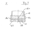
- ein Detailbild der Figur 3,3 shows a detailed picture of FIG. 3,
- Figur 5Figure 5
- einen Stempel und ein Schneidgitter des Knoblauchschneiders im Detail, a stamp and a cutting grid of the Garlic cutter in detail,
- Figur 6aFigure 6a
- einen Blick von unten auf ein erfindungsgemäßes Gerät,a view from below of an inventive Device,
- Figur 6bFigure 6b
- ein Detailbild der Einzeilheit H gemäß Figur 6,6 shows a detailed picture of the one-row unit H according to FIG.
- Figuren 7a, 7bcharacters 7a, 7b
- zwei Schnitte durch eine Überwurfmutter undtwo cuts through a union nut and
- Figur 8Figure 8
- ein Detail aus Figur 2.a detail from Figure 2.
Der Knoblauchschneider gemäß Figur 1 weist einen Griffteil 1
auf, an dem einige Griffmulden ausgeformt sind, damit die von
der Hand aufgebrachte Drehkraft besser eingeleitet werden kann.
Der Griffteil 1 sitzt auf dem Oberteil 2 und ist gegenüber dem
Gehäusekörper 6 drehbar. Am Gehäusekörper 6 ist oben die
Überwurfmutter 3 befestigt. Der Gehäusekörper 6 geht unten in
den Messerhalter 9 über. Dieser ist verbreitert, um eine
vergrößerte Standfläche zu bilden. Die Überwurfmutter 3 weist
ebenfalls eine Riffelung mit Mulden auf, um eine leichtere
Handhabung zu gewährleisten.The garlic cutter according to FIG. 1 has a
Figur 2 zeigt in einem Schnitt den Innenaufbau des
Knoblauchschneiders. Zu erkennen sind Griff 1, Oberteil 2 und
der darin befestigte Stempel 12, der über die Spindel 4 mit dem
Oberteil 2 befestigt ist. Diese Bauteile bilden eine Einheit.
Das Unterteil des Gerätes wird im wesentlichen vom
Gehäusekörper 6 gebildet, der unten den verbreiterten
Messerhalter 9 als Standfläche hat und auf dem oben die
Überwurfmutter 3 aufgeschraubt ist. Innerhalb des
Gehäusekörpers 6 ist drehbar der Innenkörper 7 auf einem (nicht
gesondert dargestellten) Metallring als Gleitelement gelagert.
Bei einem Verdrehen des Oberteils 2 wird der Innenkörper 7
ebenfalls in Rotation versetzt. Am unteren Ende des
Innenkörpers 7 befindet sich am Rahmen 5a befestigt das
Schneidgitter 5b, welches sich bei einer Drehung des Stempels
12 ebenfalls mitdreht. Fest gegenüber dem Gehäusekörper 6 steht
dagegen der Messerhalter 9 mit dem Messer 8. In der
Überwurfmutter 3 ist ein Sprengring 10 angeordnet, der
seinerseits vom Haltering 11 innerhalb der Überwurfmutter 3
gehalten ist.Figure 2 shows a section of the internal structure of the
Garlic cutter. You can see handle 1,
Figur 2 zeigt den erfindungsgemäßen Knoblauchschneider in
Öffnungszustand, d.h. die Überwurfmutter 3 ist zwar auf den
Gehäusekörper 6 aufgelegt, aber noch nicht verrastet. Deshalb
ist der Sprengring 10 auch noch geöffnet und mit seiner
Innenseite, die einen Teil eines Gegengewindes trägt, noch
nicht gegen das Gewinde der Spindel 4 gedrückt. In dieser
Stellung kann das Oberteil 2 kann also durch den Springring 10
durchgezogen werden, ohne einzugreifen. Der Betriebszustand
wird dadurch erreicht, daß die Überwurfmutter 3 verrastet, also
gegen den Gehäusekörper 6 verdreht wird, wodurch der Sprengring
10 zusammengedrückt wird und sein Gewindegang 10a in Eingriff
mit dem Gewinde der Spindel 4 kommt. Wird dann der Griff 1 mit
dem Oberteil 2 verdreht, schraubt sich die Spindel 4 langsam
gegen den Sprengring 10 nach unten und presst den Knoblauch,
der sich unterhalb des Stempels 12 und oberhalb des
Schneidgitters 5b befindet durch das Schneidgitter 5b. Dabei
entstehen im Schneidgitter 5b feine Knoblauchstäbchen, die beim
Rotieren des Schneidgitters 5b über das Messer 8 in keine
Quader zerschnitten werden.Figure 2 shows the garlic cutter according to the invention in
State of opening, i.e. the
Zum Öffnen und Zerlegen des Gerätes wird die Überwurfmutter 3
wieder um einen kurzen Winkelbetrag gedreht, wodurch der
Sprengring 10 freigegeben wird, der Gewindegang 10a nicht mehr
in das Gewinde der Spindel 4 eingreift und damit die Spindel 4
einfach aus dem Unterteil bzw. Gehäusekörper 6 herausgezogen
werden kann. Die Überwurfmutter 3 ist bevorzugt unverlierbar
auf der Spindel 4 zwischen Griff 1 und Stempel 12 gehalten.To open and dismantle the device, the
Figur 3 zeigt den Knoblauchschneider im geöffneten Zustand. Zu
erkennen ist, dass das Oberteil 2 aus dem Griff 1, dem Oberteil
2 mit Spindel 4 und Stempel 12 besteht, wobei die
Überwurfmutter 3 locker über der Spindel 4 liegt, in diese
jedoch nicht eingreift. Im Unterteil ist der Gehäusekörper 6,
der Innenkörper 7 mit Führungsnuten 7a und das Schneidgitter 5b
zu sehen. Ebenso der Messerhalter 9. Im Oberteil 2 ist im
Schnittbild der Endanschlag 2a zu erkennen, der dann, wenn das
Oberteil 2 bei ganz heruntergeschraubter Spindel 4 auf der
Überwurfmutter 3 fast zum Ruhen kommt, mit einem entsprechenden
Nocken oder Zapfen innerhalb der Überwurfmutter 3 so in Wirkung
tritt, daß eine Gegeneinanderverdrehung bzw. eine Weiterdrehung
unmöglich ist. Hierdurch wird vermieden, daß der Stempel 12 zu
tief in das Schneidgitter 5b gedrückt wird.Figure 3 shows the garlic cutter in the open state. To
can be seen that the
Innerhalb der Überwurfmutter 3 ist zu erkennen, daß sich der
Sprengring 10 in Öffnungsstellung befindet, d.h. nach außen
gespreizt ist, so daß sein nach innen wirkender Gewindegang
nicht in das Gewinde der Spindel 4 eingreift. Die
Überwurfmutter 3 ist damit leicht über die Spindel 4 hin- und
herbewegbar.Within the
Gemäß Figuren 2a und 4 weist der Stempel 12 eine Vielzahl von
Stiften 13 auf, denen eine Platte 12b zugeordnet ist, die so
viele Löcher enthält, wie Stifte 13 vorhanden sind. Die Platte
12b ist über vier Klammern 12a an dem Stempel 12 befestigt.
Gezeigt sind weiterhin vier Federn 12c, welche die Platte 12b
vom Stempel 12 wegdrücken. Erst wenn die Platte 12b am Ende des
Pressvorgangs auf das hier nicht gezeigte Schneidgitter 5b
auftrifft, wird die Platte 12b vom Gitter aufgehalten und gegen
den Stempel 12 geschoben. Die Federn 12c drücken sich zusammen,
die Stifte 12 beginnen, über die Platte 12b heraus zu ragen.
Sie reichen durch die Öffnungen des Schneidgitters 5b und
schieben so auch die letzten Knoblauchreste durch das Gitter
gegen das darunter rotierende Messer 8. In diesem gedrückten
Endzustand sind die oberseitigen Haken der Klammern 12a vom
Stempel 12 abgehoben. Öffnet der Benutzer den
Knoblauchschneider oder schraubt er den Stempel 12 wieder hoch,
so drücken die Federn 12c die Platte 12b wieder nach unten, so
dass eine praktisch ebene Fläche, gebildet aus der Platte 12b
und den Vorderseiten der Stifte 13 entsteht.According to FIGS. 2a and 4, the
Figur 5 zeigt diese Ausführung des erfindungsgemäßen Stempels
noch einmal in einer Draufsicht. Zu erkennen ist wieder der an
der Spindel 4 befestigte Stempel 12 mit den hier rund
ausgebildeten Stiften 13 und die Platte 12b mit den
entsprechend geformten Löchern. Die Platte 12b ist mit den
Klammern 12a am Stempel 12 befestigt und wird von den hier
nicht gezeigten Federn, von denen z.B. fünf Stück über fünf
Stiften 13 sitzen, nach unten gedrückt. Zu erkennen ist, dass
die Zahl der Löcher im Schneidgitter 5b mit der Zahl der Stifte
13 übereinstimmt.Figure 5 shows this embodiment of the stamp according to the invention
again in a top view. You can see that again
the
Figur 6a zeigt einen Blick von unten auf den geschlossenen
Knoblauchschneider. Zu erkennen ist der Messerhalter 9, der auf
dem Gehäusekörper 6 mittels Bajonettverschluss (hier
Linksdrehung zum Öffnen) aufgesetzt ist. Der Messerhalter 9
trägt einen Steg, der etwas außerhalb der Mitte des Gerätes
angeordnet ist, und der über ca. die Hälfte seiner Länge das
Messer 8 trägt. Dieses Messer 8 steht im Betrieb fest, während
das Schneidgitter 5b mit dem Stempel 12 sich im Betrieb über
das Messer 8 hinweg dreht. Zu erkennen sind die Stifte 13, die
Platte 12b sowie der Rahmen 5a für das Schneidgitter 5b.Figure 6a shows a view from below of the closed
Garlic cutter. You can see the
Figur 6b zeigt ein Detailbild des oben gezeigten Gerätes, wobei
noch einmal sowohl das Messer 8 als auch das Schneidgitter 5b
zu erkennen ist. Ebenso die Stifte 13 und die Platte 12 b.Figure 6b shows a detailed picture of the device shown above, wherein
again both the
Figuren 7a und 7b zeigen zwei Schnitte durch das
erfindungsgemäße Gerät in Höhe der Überwurfmutter 3. Das obere
Teilbild 7a zeigt die Überwurfmutter 3 im Betriebszustand. Die
Überwurfmutter 3 ist mit dem Bajonettverschluss am
Gehäusekörper 6 verrastet, von dem die Nasen 6a zu erkennen
sind. Diese sind mit zunehmender Dicke ausgebildet, so dass
beim Verdrehen der Überwurfmutter 3 gegen den Gehäusekörper 6
die Nasen 6a auf entsprechend angeordnete Zapfen des
Sprengrings 10 wirken und diesen nach innen, an die Spindel 4,
drücken. Dadurch greift der Gewindegang 10a in das Gewinde der
Spindel 4 und führt beim Verdrehen zu einer axialen Auf- und
Abbewegung des Stempels 12.Figures 7a and 7b show two sections through the
device according to the invention at the level of the
Das Teilbild 7b zeigt die Überwurfmutter 3 im gelösten Zustand
(Öffnungszustand). Die Nasen 6a drücken nicht mehr auf die
entsprechenden Vorsprünge des Sprengringes 10. Dieser ist durch
seine Eigenelastizität aufgesprungen und drückt seinen
Gewindegang 10a nicht mehr in das Gewinde der Spindel 4. Die
Spindel 4 ist damit aus dem Unterteil des Knoblauchschneiders
herausziehbar oder leicht hineinschiebbar.The partial picture 7b shows the
Figur 8 zeigt schließlich nochmals ein Detail aus Figur 3,
nämlich in einem seitlichen Schnitt den Eingriff des
Gewindeganges 10a in das Gewinde der Spindel 4, wenn der
Sprengring 10 durch nach innen wirkende Kräfte gegen die
Spindel 4 gedrückt ist, wenn er sich also in Betriebsstellung
befindet. FIG. 8 finally shows a detail from FIG. 3,
namely in a lateral section the engagement of the
- 11
- Griffteilhandle part
- 22
- Oberteiltop
- 33
- ÜberwurfmutterNut
- 44
- Spindelspindle
- 5a5a
- Rahmenframe
- 5b5b
- Schneidgittercutting grid
- 66
- Gehäusekörperhousing body
- 6a6a
- Nasenose
- 77
- Innenkörperinner body
- 88th
- Messerknife
- 99
- Messerhalterknife holder
- 1010
- Sprengringsnap ring
- 10a10a
- Gewindegangthread
- 1111
- Halterungbracket
- 1212
- Stempelstamp
- 12a12a
- Klammerclip
- 12b12b
- Platteplate
- 12c12c
- Federnfeathers
- 1313
- Stiftpen
Claims (10)
Applications Claiming Priority (3)
| Application Number | Priority Date | Filing Date | Title |
|---|---|---|---|
| DE19805933A DE19805933C1 (en) | 1998-02-13 | 1998-02-13 | Garlic press for domestic use |
| DE19805933 | 1998-02-13 | ||
| EP99902543A EP0975456B1 (en) | 1998-02-13 | 1999-01-15 | Device for chopping garlic |
Related Parent Applications (1)
| Application Number | Title | Priority Date | Filing Date |
|---|---|---|---|
| EP99902543A Division EP0975456B1 (en) | 1998-02-13 | 1999-01-15 | Device for chopping garlic |
Publications (1)
| Publication Number | Publication Date |
|---|---|
| EP1252990A1 true EP1252990A1 (en) | 2002-10-30 |
Family
ID=7857627
Family Applications (2)
| Application Number | Title | Priority Date | Filing Date |
|---|---|---|---|
| EP99902543A Expired - Lifetime EP0975456B1 (en) | 1998-02-13 | 1999-01-15 | Device for chopping garlic |
| EP02016711A Withdrawn EP1252990A1 (en) | 1998-02-13 | 1999-01-15 | Cutting device for vegetables particular for cutting garlic |
Family Applications Before (1)
| Application Number | Title | Priority Date | Filing Date |
|---|---|---|---|
| EP99902543A Expired - Lifetime EP0975456B1 (en) | 1998-02-13 | 1999-01-15 | Device for chopping garlic |
Country Status (13)
| Country | Link |
|---|---|
| US (1) | US5947016A (en) |
| EP (2) | EP0975456B1 (en) |
| JP (1) | JP3210970B2 (en) |
| KR (1) | KR100346255B1 (en) |
| CN (1) | CN1167538C (en) |
| AT (1) | ATE235996T1 (en) |
| AU (1) | AU735122B2 (en) |
| CA (1) | CA2286247C (en) |
| DE (3) | DE19805933C1 (en) |
| ES (1) | ES2196759T3 (en) |
| HK (1) | HK1025532A1 (en) |
| TW (1) | TW396097B (en) |
| WO (1) | WO1999041045A1 (en) |
Families Citing this family (49)
| Publication number | Priority date | Publication date | Assignee | Title |
|---|---|---|---|---|
| DE29811295U1 (en) * | 1998-06-25 | 1998-09-03 | Repac Petra | Garlic cutter |
| DE19948168C1 (en) * | 1999-10-07 | 2001-01-11 | Repac Petra | Garlic press has rotatable housing upper part with press element used to press garlic through blade mesh via axial displacement upon selective engagement of screw thread provided by housing body |
| GB2360693A (en) * | 2000-03-28 | 2001-10-03 | Paul Nicholas Wallis | Cucumber shredder |
| US20020175233A1 (en) * | 2001-05-25 | 2002-11-28 | Matt Friedlander | Mobile tire cruncher and method thereof |
| DE10223075B4 (en) * | 2002-05-24 | 2005-11-24 | Repac, Petra | vegetable cutter |
| DE10306515B4 (en) * | 2003-02-14 | 2007-07-26 | Repac, Petra | Vegetable slicer, especially onion slicer |
| US20050028685A1 (en) * | 2003-08-04 | 2005-02-10 | Hajime Yamamoto | Vegetable retainer for vegetable cooking utensil |
| US7086155B2 (en) * | 2004-07-16 | 2006-08-08 | Browne & Co. | Apparatus for coring into and cutting food items |
| DE202004011604U1 (en) * | 2004-07-23 | 2005-01-27 | Eckert, Harald | Garlic crusher, assembled of two shells each provided with integrated drop-shaped spikes |
| US8186265B2 (en) | 2005-08-08 | 2012-05-29 | Ron's Enterprises, Inc. | Device to efficiently cook food |
| US8707857B2 (en) | 2005-08-08 | 2014-04-29 | Ronald M. Popeil | Cooking device to deep fat fry foods |
| US8850965B2 (en) | 2005-08-08 | 2014-10-07 | Ronald M. Popeil | Device to efficiently cook food |
| US7367519B2 (en) * | 2006-05-12 | 2008-05-06 | Dart Industries Inc. | Processing tool for foodstuffs |
| EP2039273B1 (en) * | 2007-09-20 | 2012-04-11 | So, Kwok Kuen | Food processing device |
| DE202008002233U1 (en) * | 2008-02-18 | 2008-06-12 | Repac, Cedomir | slicer |
| US8046921B2 (en) * | 2008-03-28 | 2011-11-01 | Focus Products Group, Llc | Apparatus for coring and wedging food items |
| US20090282990A1 (en) * | 2008-05-19 | 2009-11-19 | Farnum Ronald C | Apparatus for cutting food items |
| DE102008053926B4 (en) * | 2008-10-30 | 2014-12-31 | Leifheit Ag | Food mincer |
| NL2002162C (en) | 2008-11-03 | 2010-05-04 | Mepal Bv | GARLIC PRESS. |
| US8677895B2 (en) * | 2008-12-19 | 2014-03-25 | Whirlpool Corporation | Food processor with dicing element |
| US8943954B2 (en) * | 2008-12-19 | 2015-02-03 | Whirlpool Corporation | Food processor with cleaning tool |
| US8051769B2 (en) * | 2008-12-19 | 2011-11-08 | Whirpool Corporation | Food processor with cleaning tool |
| FR2948053B1 (en) * | 2009-07-15 | 2011-07-29 | Hameur Sa | ASSEMBLY AND METHOD FOR CLEANING A GRID |
| CN101785637B (en) * | 2010-01-01 | 2015-05-06 | 王一川 | Hand-operated cutting-extrusion type garlic masher |
| CN101785636B (en) * | 2010-01-01 | 2015-05-06 | 王一川 | High-capacity hand-pressing cut-squeezing garlic mashing machine |
| US9004385B2 (en) | 2010-03-24 | 2015-04-14 | Re-Pet Ltd. | Shredding machine |
| USD730704S1 (en) | 2011-06-22 | 2015-06-02 | Genius Gmbh | Food cutting device |
| KR101395782B1 (en) * | 2012-02-24 | 2014-05-15 | 나명운 | Thin cutting utensil |
| US9119498B2 (en) | 2012-03-08 | 2015-09-01 | Grace Manufacturing, Inc. | Culinary extruding and mincing tool |
| DE202012003785U1 (en) | 2012-04-13 | 2013-07-17 | Ds Produkte Gmbh | Device for cutting food |
| US9439539B2 (en) | 2012-10-18 | 2016-09-13 | Whirlpool Corporation | Dicing tool for domestic food processing device |
| US9622620B2 (en) * | 2012-11-19 | 2017-04-18 | Helen Of Troy Limited | Device for cutting small food items |
| USD734108S1 (en) * | 2013-03-09 | 2015-07-14 | Evriholder Products, Llc | Cupcake corer |
| CN103395091B (en) * | 2013-08-16 | 2015-07-15 | 阮仕荣 | Tiny particle preparation and distribution system |
| USD737107S1 (en) | 2014-05-21 | 2015-08-25 | Grace Manufacturing, Inc. | Grater |
| USD761612S1 (en) * | 2014-09-02 | 2016-07-19 | Donald Lee Darnell | Food preparation device |
| USD749918S1 (en) | 2014-09-18 | 2016-02-23 | Grace Manufacturing, Inc. | Culinary tool |
| DE102015103222A1 (en) | 2015-03-05 | 2016-09-08 | Genius Gmbh | Crushing device for cutting food, in particular for cutting garlic |
| USD785415S1 (en) | 2016-03-17 | 2017-05-02 | Grace Manufacturing, Inc. | Culinary tool |
| USD798676S1 (en) | 2016-08-04 | 2017-10-03 | Grace Manufacturing, Inc. | Culinary grater |
| USD799283S1 (en) | 2016-08-04 | 2017-10-10 | Grace Manufacturing, Inc. | Culinary grater |
| US10183410B2 (en) * | 2016-09-28 | 2019-01-22 | Progressive International Corporation | Vegetable stick maker |
| US10412981B2 (en) | 2017-02-27 | 2019-09-17 | Ronald M. Popeil | System and method for deep frying poultry while avoiding skin damage |
| CN109049024B (en) * | 2018-07-23 | 2020-06-09 | 瑞安市金意鞋业有限公司 | Domestic onion section device of negative pressure formula |
| CN109156856B (en) * | 2018-10-31 | 2021-04-27 | 山东青田食品有限公司 | Full-automatic garlic peeling machine |
| CN111070269B (en) * | 2019-11-26 | 2021-06-22 | 徐州工程学院 | Eat material section device |
| DE102021113525A1 (en) * | 2021-05-26 | 2022-12-01 | Brandivision Gmbh | Device for pressing |
| US11897157B1 (en) * | 2023-03-15 | 2024-02-13 | Bruce Feldman | Garlic mincer |
| CN116037297B (en) * | 2023-03-31 | 2023-07-11 | 河北华裕永诚食品有限公司 | Efficient crushing device for dehydrated garlic |
Citations (2)
| Publication number | Priority date | Publication date | Assignee | Title |
|---|---|---|---|---|
| US4579028A (en) * | 1984-08-01 | 1986-04-01 | Neidhardt Edward M | Onion dicer |
| WO1992022235A1 (en) * | 1991-06-19 | 1992-12-23 | Peter Bindner | Press for squeezing vegetables, for instance garlic |
Family Cites Families (21)
| Publication number | Priority date | Publication date | Assignee | Title |
|---|---|---|---|---|
| US343840A (en) * | 1886-06-15 | Vegetable-chopper | ||
| DE131453C (en) * | ||||
| US533703A (en) * | 1895-02-05 | calla- | ||
| US2500973A (en) * | 1946-04-04 | 1950-03-21 | Ackerman Charles | Slicing machine |
| DE832051C (en) * | 1950-09-29 | 1952-02-21 | Tilo Ufer | Device for chopping onions, fruit and other goods |
| DE1750135A1 (en) * | 1968-04-02 | 1971-01-07 | Philips Patentverwaltung | Device with a cam scanning lever |
| FR2080059A5 (en) * | 1970-02-23 | 1971-11-12 | Kyvon Robert De | |
| DE2119992A1 (en) * | 1971-04-23 | 1972-10-26 | ||
| DE2232672A1 (en) * | 1972-07-04 | 1974-01-24 | Wehner Walter | DEVICE FOR CUTTING ONIONS |
| US4095518A (en) * | 1976-09-28 | 1978-06-20 | Fasline Food Equipment Co. | Sectioning device for rounded food article |
| US4436025A (en) * | 1983-04-01 | 1984-03-13 | Jones Frank W | Sectioning device for rounded food articles |
| US4569280B1 (en) * | 1984-09-26 | 1996-07-02 | Le Jo Enterprises Inc | Produce wedger |
| US4819882A (en) * | 1988-01-07 | 1989-04-11 | Whirlpool Corporation | Food processor food pusher positioning apparatus |
| US5216031A (en) * | 1991-07-26 | 1993-06-01 | The West Bend Company | Vegetable cutting device |
| US5121679A (en) * | 1991-11-12 | 1992-06-16 | Mertz Myron M | Potato cutting apparatus |
| JP2543462B2 (en) * | 1992-05-06 | 1996-10-16 | 株式会社ムロコーポレーション | Fruit and vegetable cutting cutter |
| US5271317A (en) * | 1993-03-05 | 1993-12-21 | Aguerrevere Maria S R | Potato slicer device |
| US5337480A (en) * | 1993-05-07 | 1994-08-16 | Ralph Codikow | Subdividing device |
| US5421249A (en) * | 1994-04-28 | 1995-06-06 | Milton Industries, Inc. | Food wedger |
| US5375512A (en) * | 1994-05-31 | 1994-12-27 | Ertmer; Lyle E. | Apparatus to support a fruit or vegetable on a spherical surface and to slice it with a single stroke |
| DE29713837U1 (en) * | 1997-08-02 | 1997-10-09 | Repac Petra | Garlic cutter |
-
1998
- 1998-02-13 DE DE19805933A patent/DE19805933C1/en not_active Expired - Lifetime
- 1998-05-18 DE DE29808989U patent/DE29808989U1/en not_active Expired - Lifetime
- 1998-09-04 US US09/146,756 patent/US5947016A/en not_active Expired - Lifetime
-
1999
- 1999-01-15 AU AU22795/99A patent/AU735122B2/en not_active Expired
- 1999-01-15 JP JP54095699A patent/JP3210970B2/en not_active Expired - Fee Related
- 1999-01-15 EP EP99902543A patent/EP0975456B1/en not_active Expired - Lifetime
- 1999-01-15 AT AT99902543T patent/ATE235996T1/en active
- 1999-01-15 CN CNB998001384A patent/CN1167538C/en not_active Expired - Lifetime
- 1999-01-15 EP EP02016711A patent/EP1252990A1/en not_active Withdrawn
- 1999-01-15 CA CA002286247A patent/CA2286247C/en not_active Expired - Lifetime
- 1999-01-15 WO PCT/EP1999/000215 patent/WO1999041045A1/en active IP Right Grant
- 1999-01-15 KR KR1019997009218A patent/KR100346255B1/en not_active IP Right Cessation
- 1999-01-15 ES ES99902543T patent/ES2196759T3/en not_active Expired - Lifetime
- 1999-01-15 DE DE59904812T patent/DE59904812D1/en not_active Expired - Lifetime
- 1999-02-10 TW TW088102240A patent/TW396097B/en not_active IP Right Cessation
-
2000
- 2000-08-01 HK HK00104791A patent/HK1025532A1/en not_active IP Right Cessation
Patent Citations (2)
| Publication number | Priority date | Publication date | Assignee | Title |
|---|---|---|---|---|
| US4579028A (en) * | 1984-08-01 | 1986-04-01 | Neidhardt Edward M | Onion dicer |
| WO1992022235A1 (en) * | 1991-06-19 | 1992-12-23 | Peter Bindner | Press for squeezing vegetables, for instance garlic |
Also Published As
| Publication number | Publication date |
|---|---|
| EP0975456B1 (en) | 2003-04-02 |
| KR100346255B1 (en) | 2002-07-26 |
| CA2286247A1 (en) | 1999-08-19 |
| US5947016A (en) | 1999-09-07 |
| EP0975456A1 (en) | 2000-02-02 |
| WO1999041045A1 (en) | 1999-08-19 |
| CN1256657A (en) | 2000-06-14 |
| AU2279599A (en) | 1999-08-30 |
| JP3210970B2 (en) | 2001-09-25 |
| TW396097B (en) | 2000-07-01 |
| DE59904812D1 (en) | 2003-05-08 |
| JP2000515439A (en) | 2000-11-21 |
| KR20010006139A (en) | 2001-01-26 |
| CN1167538C (en) | 2004-09-22 |
| CA2286247C (en) | 2002-02-05 |
| ATE235996T1 (en) | 2003-04-15 |
| ES2196759T3 (en) | 2003-12-16 |
| DE29808989U1 (en) | 1998-07-30 |
| AU735122B2 (en) | 2001-06-28 |
| DE19805933C1 (en) | 1999-04-15 |
| HK1025532A1 (en) | 2000-11-17 |
Similar Documents
| Publication | Publication Date | Title |
|---|---|---|
| EP0975456B1 (en) | Device for chopping garlic | |
| EP0967056B1 (en) | Garlic chopper | |
| EP1137518B1 (en) | Device for dicing garlic | |
| EP0143103B1 (en) | Hand press for vegetables or fruits | |
| WO2012150044A1 (en) | Cutting insert for a foodstuff chopping apparatus | |
| EP1829655B1 (en) | Device for cutting fruit and vegetables, in particular onions | |
| DE10223075A1 (en) | Vegetable chopper for chopping vegetables comprises a housing lower part, a housing upper part, and devices which in the operating state engage in a thread of a spindle and in the open state allow free axial displacement of the spindle | |
| DE102009035511A1 (en) | kitchen appliance | |
| EP0717599B1 (en) | Device for peeling elongated vegetables | |
| EP2641515A1 (en) | Fruit flesh cutter | |
| DD221073A5 (en) | ELECTRIC HOUSEHOLD APPLIANCE FOR CUTTING FRUIT, VEGETABLES AND AU. | |
| DE102005048788A1 (en) | Grit aid and storage container for food stuff e.g. onion, has compression plunger moved by turning screw nut or tie bar over cap towards grit grid, which is closed with lower side of casing or fixing ring | |
| DE19733551C2 (en) | Garlic cutter | |
| DE202005019232U1 (en) | Cutting aid and storage container for onions | |
| DE2302943C3 (en) | Kitchen appliance with a receptacle that can be slid into a filling chute | |
| DE102017120194A1 (en) | Press for vegetables, fruits and / or spices, especially garlic | |
| DE10332598B4 (en) | Fruit / Gemüsereibgerät | |
| DE202007008380U1 (en) | Device for cutting fruit, vegetables or the like. | |
| DE102014107135B3 (en) | coring device | |
| DE563168C (en) | Machine for pitting fruits, especially dried plums | |
| DE19747007A1 (en) | Food chopping device | |
| DE3430566A1 (en) | Holder for fruit, vegetables and similar foodstuffs for holding them while they are comminuted with a household appliance | |
| DE2302331A1 (en) | CUTTING DEVICE FOR CHOPPING GARDEN FRUITS, SO-CALLED ONION CUTTER | |
| DE1402343B2 (en) | Hand tool for cutting through screws and threaded bolts | |
| CH262628A (en) | Punching tool. |
Legal Events
| Date | Code | Title | Description |
|---|---|---|---|
| PUAI | Public reference made under article 153(3) epc to a published international application that has entered the european phase |
Free format text: ORIGINAL CODE: 0009012 |
|
| 17P | Request for examination filed |
Effective date: 20020726 |
|
| AC | Divisional application: reference to earlier application |
Ref document number: 975456 Country of ref document: EP |
|
| AK | Designated contracting states |
Kind code of ref document: A1 Designated state(s): AT CH DE ES FR GB IT LI NL |
|
| AX | Request for extension of the european patent |
Free format text: SI PAYMENT 20020726 |
|
| AKX | Designation fees paid |
Designated state(s): AT CH DE ES FR GB IT LI NL |
|
| AXX | Extension fees paid |
Extension state: SI Payment date: 20020726 |
|
| 17Q | First examination report despatched |
Effective date: 20040405 |
|
| STAA | Information on the status of an ep patent application or granted ep patent |
Free format text: STATUS: THE APPLICATION IS DEEMED TO BE WITHDRAWN |
|
| 18D | Application deemed to be withdrawn |
Effective date: 20050809 |