EP1251572B1 - Batteriebehälter - Google Patents
Batteriebehälter Download PDFInfo
- Publication number
- EP1251572B1 EP1251572B1 EP02008193A EP02008193A EP1251572B1 EP 1251572 B1 EP1251572 B1 EP 1251572B1 EP 02008193 A EP02008193 A EP 02008193A EP 02008193 A EP02008193 A EP 02008193A EP 1251572 B1 EP1251572 B1 EP 1251572B1
- Authority
- EP
- European Patent Office
- Prior art keywords
- housing section
- battery box
- contact preventing
- electrode terminal
- negative electrode
- Prior art date
- Legal status (The legal status is an assumption and is not a legal conclusion. Google has not performed a legal analysis and makes no representation as to the accuracy of the status listed.)
- Expired - Lifetime
Links
- 238000003780 insertion Methods 0.000 description 5
- 230000037431 insertion Effects 0.000 description 5
- PWHULOQIROXLJO-UHFFFAOYSA-N Manganese Chemical compound [Mn] PWHULOQIROXLJO-UHFFFAOYSA-N 0.000 description 3
- 230000008878 coupling Effects 0.000 description 3
- 238000010168 coupling process Methods 0.000 description 3
- 238000005859 coupling reaction Methods 0.000 description 3
- 229910052748 manganese Inorganic materials 0.000 description 3
- 239000011572 manganese Substances 0.000 description 3
- 229910052751 metal Inorganic materials 0.000 description 3
- 239000002184 metal Substances 0.000 description 3
- NLXLAEXVIDQMFP-UHFFFAOYSA-N Ammonia chloride Chemical compound [NH4+].[Cl-] NLXLAEXVIDQMFP-UHFFFAOYSA-N 0.000 description 2
- 239000000463 material Substances 0.000 description 2
- 238000000034 method Methods 0.000 description 2
- JIAARYAFYJHUJI-UHFFFAOYSA-L zinc dichloride Chemical compound [Cl-].[Cl-].[Zn+2] JIAARYAFYJHUJI-UHFFFAOYSA-L 0.000 description 2
- HCHKCACWOHOZIP-UHFFFAOYSA-N Zinc Chemical compound [Zn] HCHKCACWOHOZIP-UHFFFAOYSA-N 0.000 description 1
- 235000019270 ammonium chloride Nutrition 0.000 description 1
- 239000007864 aqueous solution Substances 0.000 description 1
- 230000000694 effects Effects 0.000 description 1
- 239000003792 electrolyte Substances 0.000 description 1
- 238000005516 engineering process Methods 0.000 description 1
- 239000012530 fluid Substances 0.000 description 1
- 230000002401 inhibitory effect Effects 0.000 description 1
- 230000007935 neutral effect Effects 0.000 description 1
- 238000007789 sealing Methods 0.000 description 1
- 239000011701 zinc Substances 0.000 description 1
- 229910052725 zinc Inorganic materials 0.000 description 1
- 235000005074 zinc chloride Nutrition 0.000 description 1
- 239000011592 zinc chloride Substances 0.000 description 1
Images


Classifications
-
- H—ELECTRICITY
- H01—ELECTRIC ELEMENTS
- H01M—PROCESSES OR MEANS, e.g. BATTERIES, FOR THE DIRECT CONVERSION OF CHEMICAL ENERGY INTO ELECTRICAL ENERGY
- H01M50/00—Constructional details or processes of manufacture of the non-active parts of electrochemical cells other than fuel cells, e.g. hybrid cells
- H01M50/20—Mountings; Secondary casings or frames; Racks, modules or packs; Suspension devices; Shock absorbers; Transport or carrying devices; Holders
- H01M50/204—Racks, modules or packs for multiple batteries or multiple cells
- H01M50/207—Racks, modules or packs for multiple batteries or multiple cells characterised by their shape
- H01M50/213—Racks, modules or packs for multiple batteries or multiple cells characterised by their shape adapted for cells having curved cross-section, e.g. round or elliptic
-
- H—ELECTRICITY
- H01—ELECTRIC ELEMENTS
- H01M—PROCESSES OR MEANS, e.g. BATTERIES, FOR THE DIRECT CONVERSION OF CHEMICAL ENERGY INTO ELECTRICAL ENERGY
- H01M50/00—Constructional details or processes of manufacture of the non-active parts of electrochemical cells other than fuel cells, e.g. hybrid cells
- H01M50/20—Mountings; Secondary casings or frames; Racks, modules or packs; Suspension devices; Shock absorbers; Transport or carrying devices; Holders
- H01M50/271—Lids or covers for the racks or secondary casings
-
- H—ELECTRICITY
- H01—ELECTRIC ELEMENTS
- H01M—PROCESSES OR MEANS, e.g. BATTERIES, FOR THE DIRECT CONVERSION OF CHEMICAL ENERGY INTO ELECTRICAL ENERGY
- H01M50/00—Constructional details or processes of manufacture of the non-active parts of electrochemical cells other than fuel cells, e.g. hybrid cells
- H01M50/50—Current conducting connections for cells or batteries
- H01M50/572—Means for preventing undesired use or discharge
- H01M50/584—Means for preventing undesired use or discharge for preventing incorrect connections inside or outside the batteries
- H01M50/588—Means for preventing undesired use or discharge for preventing incorrect connections inside or outside the batteries outside the batteries, e.g. incorrect connections of terminals or busbars
-
- H—ELECTRICITY
- H01—ELECTRIC ELEMENTS
- H01M—PROCESSES OR MEANS, e.g. BATTERIES, FOR THE DIRECT CONVERSION OF CHEMICAL ENERGY INTO ELECTRICAL ENERGY
- H01M50/00—Constructional details or processes of manufacture of the non-active parts of electrochemical cells other than fuel cells, e.g. hybrid cells
- H01M50/10—Primary casings; Jackets or wrappings
- H01M50/102—Primary casings; Jackets or wrappings characterised by their shape or physical structure
- H01M50/107—Primary casings; Jackets or wrappings characterised by their shape or physical structure having curved cross-section, e.g. round or elliptic
-
- Y—GENERAL TAGGING OF NEW TECHNOLOGICAL DEVELOPMENTS; GENERAL TAGGING OF CROSS-SECTIONAL TECHNOLOGIES SPANNING OVER SEVERAL SECTIONS OF THE IPC; TECHNICAL SUBJECTS COVERED BY FORMER USPC CROSS-REFERENCE ART COLLECTIONS [XRACs] AND DIGESTS
- Y02—TECHNOLOGIES OR APPLICATIONS FOR MITIGATION OR ADAPTATION AGAINST CLIMATE CHANGE
- Y02E—REDUCTION OF GREENHOUSE GAS [GHG] EMISSIONS, RELATED TO ENERGY GENERATION, TRANSMISSION OR DISTRIBUTION
- Y02E60/00—Enabling technologies; Technologies with a potential or indirect contribution to GHG emissions mitigation
- Y02E60/10—Energy storage using batteries
Definitions
- the present invention relates to a structure of a battery box in which a dry battery is introduced and secured, and in particular, to a technology for preventing an accidental event resulting from a short-circuit condition of the dry battery.
- typical dry batteries used for the electrical appliances include a manganese dry battery and an alkaline dry battery, and recently, the alkaline dry battery having a high capacity and an excellent discharge property at a high current has been commonly used in various fields.
- This alkaline dry battery is similar to the manganese dry battery in an external appearance and a size but more or less different from that in used material and structure.
- the manganese dry battery is produced by filling a zinc can with various materials such as zinc chloride and neutral aqueous solution of ammonium chloride, which will be finally sealed with a tube referred to as a metal jacket
- the alkaline dry battery is produced by filling an outer case referred to as a positive electrode can with electrolyte and separator prepared as the stuffs, sealing the can, and then wrapping around said can a label indicating a performance of the battery and/or a caution therefor.
- the positive electrode in the alkaline dry battery the positive electrode can is wrapped with the label sheathing and this label sheathing is thin and apt to be torn.
- the positive electrode can and a collector are sealed in their openings, there should be a recess in a connecting surface between them and thus a space created between the label sheathing and the connecting surface. Owing to this, a portion of interest defined in a lower region of the dry battery (at cathode side) has been more apt to be broken.
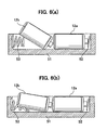
- Fig. 5(a) is a sectional view showing a structure of a battery box according to the prior art, which comprises a positive electrode terminal 52 and a negative electrode terminal 53 each serving as contact in the left or the right side within the battery box 51. It is to be noted that this battery box is of a type in which two of the dry batteries are received longitudinally one after another.
- a second one of the batteries 12b is inserted with its cathode side inclined downwardly, as shown in Fig. 5(b).
- the second one of the dry batteries 12a may be set in the battery box from the positive electrode terminal side of the battery box, as shown in Fig. 5(c).
- Fig. 6(a) shows a case where an erroneous inserting method has been applied to insertion of the alkaline dry batteries into the prior art battery box.
- a lateral face of the dry battery 12b could come into contact with the spring-shaped negative electrode terminal 53.
- the dry batteries could be received within the battery box 51 in the condition that the spring is deformed as being collapsed as shown in Fig. 6(b).
- the dry batteries used in this case are the alkaline dry batteries
- the spring-shaped negative electrode terminal 53 made of metal would tear the label sheathing of the outermost layer, thereby bringing the positive electrode can inside thereof into a stripped-out condition.
- the spring comes into contact with the positive electrode can and the cathode of the dry battery at the same time, it would result in a short-circuit condition (a short).
- the short-circuit between both electrode terminals of the dry battery could not only reduce the operating life of the dry battery as commonly known well but also induce a heat developed inside thereof and/or a fluid leakage therefrom.
- JP 10 321205 A relates to a battery housing part of a battery housing apparatus, wherein a negative electrode terminal member is installed in a rear side of the inside of the battery housing part and a guide member is formed in an aperture side of the battery housing part, so as to cover the negative electrode terminal member, so that the negative electrode terminal side of the battery can slip under the lower part of the guide member to contact the negative electrode terminal member.
- the present invention has been made in the light of the circumstance described above, and an object thereof is to provide a battery box which can prevent an erroneous insertion of a dry battery thereby avoiding a short-circuit condition thereof.
- the battery box according to the present invention is defined by the features contained in claim 1.
- said contact preventing member is formed as a bridge section which is bridged across said housing section in the direction crossing the longitudinal direction of said housing section.
- said contact preventing member is formed as a protrusion which is protruding toward an inside of said housing section in the direction crossing the longitudinal direction of said housing section.
- said contact preventing member extends only along a region proximal to a front end portion of said negative electrode terminal with respect to said longitudinal direction.
- said contact preventing member extends from a region proximal to a front end portion of said negative electrode terminal to a region proximal to an end portion of said housing section with respect to said longitudinal direction.
- said contact preventing members are disposed on respective side walls in opposite sides of said housing section.
- said contact preventing member is disposed on a side wall in one side of said housing section.
- a degree of protrusion of one of the contact preventing members is different from the degree of protrusion of the other one of the contact preventing members.
- a battery box according to the present invention further comprises a lid for covering said housing section and said lid has a through hole formed in such a location in which said contact preventing member can penetrate through said lid when the lid is closed.
- a battery box according to the present invention is provided with a contact preventing member on an upper surface of said sell box in the proximity to a terminal, so that said member functions as a stopper to prevent a lateral face of a dry battery from coming into contact with said terminal.
- the lid is provided with a through hole so as to avoid the interference of the contact preventing member with the lid when the lid is closed.
- the negative electrode terminal of the battery box has a spring-like shape, it can help to provide a sufficient contact of the dry battery with the terminal as well as a measure for preventing an erroneous insertion of the dry battery.
- the contact preventing means arranged in a location above at least one of a positive electrode terminal or a negative electrode terminal can prevent the lateral face of the dry battery to be inserted in the battery box from coming into contact with either terminal.
- the contact preventing means is formed as a bridge section bridged across a housing section along a direction crossing the longitudinal direction of the housing section, it can reliably prevent the dry battery from coming into contact with the terminal.
- the contact preventing member is formed as a protrusion which protrudes toward an inside of the housing section along the direction crossing the longitudinal direction of the housing section, it becomes possible that the contact preventing member is prohibited from protruding upwardly over an upper edge of the housing section and that said member is made compact. In addition, in this case, it is possible to avoid an interference of the contact preventing member with the lid even when the lid is closed, without any through holes formed in the lid.
- the contact preventing member extends only along a region proximal to a front end portion of the negative electrode terminal with respect to the longitudinal direction, a structure of the contact preventing member can be simplified.
- the contact preventing member extends from the region proximal to the front end portion of the negative electrode terminal to a region proximal to an end portion of the housing section with respect to the longitudinal direction, a strength of the contact preventing member can be further increased.
- the contact preventing members are provided on both side walls of the housing section, they can reliably prevent the dry battery from coming into contact with the terminal.
- the contact preventing member is provided on one side wall of the housing section, it can reliably prevent the lateral face of the dry battery from coming into contact with the terminal of the battery box even if there is no space available for providing the contact preventing member on the other side wall of the housing.
- the contact preventing member can be provided corresponding to an extent of the space available on the side wall in the other one side of the housing section.
- a lid for covering the housing section is further provided and a through hole is formed in said lid to permit the contact preventing member to pass through it when the lid is closed, therefore it can prevent the contact preventing member from coming into contact with the lid when the lid is closed.
- the negative electrode terminal is a negative electrode terminal and said negative electrode terminal is formed in an elastically deformable spring-like shape, therefore an sufficient contact between the dry battery and the terminal can be accomplished and an erroneous insertion of the dry battery can be still prevented.
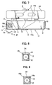
- Fig. 1 is an external plan view of a battery box according to the present invention, which is of a type for receiving two dry batteries aligned longitudinally in series, shown with a lid being opened.
- This battery box 1 has a U-shaped housing section 10 with its upper portion being open, and further comprises a positive electrode terminal 2 and a negative electrode terminal 3 arranged respectively on inner end walls 16a and 16b of the housing section 10 so as to oppose with each other.
- a minimum size of the interior of the housing section 10 is defined as such a size that can allow the inserted dry batteries to be fittingly accommodated in the housing section 10 when a lid 5 is closed.
- the positive electrode terminal 2 is a contact formed by folding a commonly-used metal plate, and the negative electrode terminal is one having a spring-like shape.
- a contact preventing member 4 functioning as a stopper is disposed in a spaced relationship from the negative electrode terminal 3 by a small distance. Preferably, this distance should be approximately equal to a free length "d" of the spring-shaped negative electrode terminal 3 (which will be described below in detail).
- the contact preventing member 4 is disposed above the negative electrode terminal side.
- the contact preventing member 4 may be formed to be integral with the housing 10 as a part thereof. According to the first embodiment of the present invention, this contact preventing member 4 is formed in a location above a region proximal to a front end portion 3a of the negative electrode terminal 3 as a bridge section bridged between side walls 17a and 17b of the housing section 10 along a direction crossing the longitudinal direction connecting one end to the other end of the housing section 10, for example, along the direction approximately orthogonal to the longitudinal direction as shown in Fig. 3.
- a main body section 4a of the contact preventing member 4 is formed in a bar-shape having an approximately uniform thickness (see Fig. 2, which will be described later).
- either end portion 4b of the contact preventing member 4 is chamfered, though not clearly seen from the drawing.
- a location in which the contact preventing member 4 is to be arranged is defined in such a location that can effectively prevent the contact of the lateral face of the dry battery to be inserted with the negative electrode terminal 3. For example, if the contact preventing member 4 is disposed along the direction approximately orthogonal to the longitudinal direction of the housing section 10 as shown in Fig.
- the contact preventing member 4 should be disposed in an appropriate location such that the distance "d" defined as from the inner end wall 16b of the housing section 10, on which a rear end portion 3b of the negative electrode terminal 3 is secured, to the front end portion 3a of the negative electrode terminal is approximately equal to or slightly less than the distance "d'" defined as from the inner end wall 16b to the contact preventing member 4 (to a side face thereof more distant from the inner wall 16b).
- the case of the former distance "d" being somewhat smaller than the latter distance "d'" is shown.
- the contact preventing member 4 is shown to have a relatively greater length of the distance "d" in comparison with the length of the housing 10 in the longitudinal direction in order to emphasize the location of the contact preventing member 4 (and the size of the negative electrode terminal 3), the distance "d" should be practically smaller than that shown in the drawing.
- a lid 5 for covering the battery box 1 is provided via coupling sections 6, and a through hole 7 is formed in a part of the lid 5.
- These lid 5 and coupling sections 6 are not necessarily required but may be eliminated.
- the inner side of the lid 5 includes an illustration P for giving an instruction on the inserting direction of the dry batteries, as shown in Fig. 1. It is to be noted that the housing section 10, the lid 5 and the coupling sections 6 maybe integrally formed as a single body.
- the battery box 1 further comprises a pawl 8 and an engaging latch section 9 so as to prevent the lid 5 from detaching from a main body side of the battery box 1 when the lid 5 is closed.
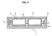
- Fig. 2 is a sectional view of the battery box taken along the line A-A' of Fig. 1.
- the contact preventing member 4 is arranged in such a manner that it is protruding from an upper edge 13 of the housing 10 (which is on the level equal to the height of the dry batteries inserted in the housing 10) upwardly (toward the lid 5 side) to some degree.
- FIG. 3 (a) shows the dry batteries to be inserted in the battery box 1, and in the case of inserting the two dry batteries longitudinally aligned in series, typically one of the dry batteries should be inserted first and then the other of the dry batteries should be entered diagonally, wherein if upon insertion, the dry battery 12a has been precedently set in the battery box 1 in the positive electrode terminal 2 side, and when the other of the dry batteries 12b is to be inserted, the dry battery 12b is entered diagonally with its anode side inclined downwardly as shown in Fig. 3 (a), then the lateral face of the dry battery 12b in the cathode side will come into contact with the upper side of the contact preventing member 4 acting as the stopper, thereby inhibiting the dry battery 12b from being fully entered.
- the contact preventing member 4 functions as the stopper with respect to the dry battery 12b, the contact of the lateral face of the dry battery 12b with the negative electrode terminal 3 could be avoided, which might have occurred in the prior art.
- the dry battery 12a has been precedently set in the battery box 1 in the positive electrode terminal 2 side and the other dry battery 12b is to be inserted with its cathode side inclined downwardly, as shown in Fig. 3(b)
- the lateral face of the dry battery 12b would come into contact with the lower side of the contact preventing member 4, but nevertheless the dry battery 12b could be allowed to enter between the contact preventing member 4 and a bottom face 18 of the housing section 10 and slide in below the contact preventing member 4.
- the lateral face of the dry battery 12b would not come in contact with the negative electrode terminal 3 and the two dry batteries (especially the dry battery 12b) can be completely inserted in the battery box 1.
- the two dry batteries may be set as they are aligned longitudinally in series by setting a first one of the dry batteries 12b in the battery box in its negative electrode terminal 3 side in a similar manner to that shown in Fig. 3 (b) and then setting the other dry battery 12a in the battery box in its positive electrode terminal 2 side.
- the lateral face of the dry battery would not come into contact with the negative electrode terminal 3 and the two dry batteries can be completely inserted in the battery box 1.
- the contact preventing member (the stopper) is disposed at the location apart from the inner end wall 16b by a distance approximately equal to the length of the negative electrode terminal 3
- the lateral face of the dry battery would never come in contact with the negative electrode terminal, and thus there would be no fear of any tears created in a label sheathing in the case of an alkaline dry battery. Accordingly, there would be no short-circuit event induced, which has been described in the section of THE DESCRIPTION OF THE PRIOR ART, thus preventing an accident associated with the dry battery. Thereby, any failures of an electrical appliance resulting from the dry battery can be prevented as well.
- the battery box 1 of the present invention can be provided with a through hole 7 formed in the lid 5. As shown in Fig. 4, this through hole 7 is disposed in such a location that permits the contact preventing member 4 to penetrate through the lid 5 when the lid 5 is closed. As described above, since the contact preventing member 4 is chamfered in either end portion 4b, therefore the lid 5 could not bump the contact preventing member 4. This lid 5 can prevent the pop-out of the dry battery as similarly to the prior art battery box, and further, owing to the through hole provided in the lid 5, the battery box 1 with the contact preventing member 4 formed thereon can be designed without increasing the total height of the battery box.
- Fig. 7 is an external plan view of a battery box 1 according to this second embodiment of the present invention, shown in the same manner as in Fig. 1, and Fig. 8 is a sectional view taken along the line B-B' of Fig. 7. It is to be noted that differently from Fig. 7, Fig. 8 shows the battery box 1 with a lid 54 closed and a dry battery 12 housed therein. In these drawings, the members similar to those in Figs. 1 to 6 are designated by using the same reference numerals.
- contact preventing members 14 and 15 are formed above a region proximal to the front end portion 3a of the negative electrode terminal 3 as protrusions which are protruding from respective side walls 17a and 17b of a housing 10 toward the inside thereof opposing with each other along a direction crossing the longitudinal direction of the housing section 10, for example, along the direction approximately orthogonal to the longitudinal direction of the housing section 10 as shown in Fig. 7.
- Locations in which the contact preventing member 14 and 15 are to be disposed are, as similarly to the first embodiment, designed in such locations that can prevent effectively the contact of a lateral face of a dry battery with the negative electrode terminal 3. As for these locations, it should be considered that an imaginary line connecting the contact preventing members 14 and 15 with each other corresponds to the contact preventing member 4 in the first embodiment (see Figs. 3 to 5).
- each of the contact preventing members 14 and 15 should be disposed in the appropriate locations such that the distance "d" defined as from the inner end wall 16b of the housing section 10, on which the rear end portion 3b of the negative electrode terminal 3 is secured, to the front end portion 3a of the negative electrode terminal is approximately equal to or slightly less than the (shortest) distance "d'" defined as from the inner end wall 16b to the imaginary line connecting the contact preventing members 14 and 15 with each other.
- the distance "d" defined as from the inner end wall 16b of the housing section 10, on which the rear end portion 3b of the negative electrode terminal 3 is secured, to the front end portion 3a of the negative electrode terminal is approximately equal to or slightly less than the (shortest) distance "d'" defined as from the inner end wall 16b to the imaginary line connecting the contact preventing members 14 and 15 with each other.
- shortest distance "d'" defined as from the inner end wall 16b to the imaginary line connecting the contact preventing members 14 and 15 with each other.
- every part of the cross section of the contact preventing members 14 and 15 is formed by a flat surface.
- Each of the contact preventing members 14, 15 is formed at a level same as or lower than an upper edge 13 of the housing section 10, which is at a height level of the dry battery, and would never protrude upwardly over the upper edge 13 of the housing section 10 (toward the lid 54 side) .
- this lid 54 in the second embodiment is not required to have such a through hole 7 (see Figs. 3 and 5) that has been provided in the lid 5 in the first embodiment.
- the contact preventing member would never increase the total height of the battery box.
- the degrees of protrusion of the contact preventing members 14 and 15 within the housing section 10 may be different from each other.
- the contact preventing member 14 may protrude more toward the inside of the housing as compared with the contact preventing member 15 does.
- the contact preventing members are not necessarily required to be disposed on both side walls 17 opposing with each other, but the contact preventing member may be disposed on one of the side walls 17, for example, only on the side wall 17a. Further, if the contact preventing members are provided on both side walls 17, one contact preventing member on one side wall may be offset from the other contact preventing member on the other side wall in the longitudinal direction.
- the contact preventing member 14, 15 may be formed so as to protrude upwardly over the upper edge 13 of the housing section 10, as similarly to the contact preventing member 4 in the first embodiment.
- these contact preventing members 14 and 15 may be formed by dividing the contact preventing member 4 in the first embodiment (see Fig. 3) into two separate parts. It is to be realized that this variation requires a through hole to be formed in a lid as is the case with the first embodiment.
- Fig. 9 shows a variation of a sectional geometry of the contact preventing member shown in Fig. 8.
- every part of the cross section of the contact preventing members 14 and 15 has been formed by a flat surface
- a part of the cross section located in a lower side of the contact preventing member 14a, 15a is formed in a curved face corresponding to the surface contour of the dry battery.
- the cross section of the contact preventing member 14a, 15a is tapered toward the inside of the housing section 10 corresponding to the surface contour of the dry battery.
- the contact preventing member 14a, 15a can be accommodated in a relatively small apace between the dry battery and the lid 54. Further, it becomes possible to make greater the degree of protrusion of the contact preventing member 14a, 15a toward the inside of the housing 10, thereby preventing more effectively the contact of the terminal with the lateral face of the dry battery.
- Fig. 10 is an external plan view of a battery box according to the third embodiment, shown in the same manner as in Fig. 1 and Fig. 7.
- the members similar to those in Figs. 1 and 7 are designated by using the same reference numerals.
- the third embodiment should be considered a variation of the second embodiment.
- the contact preventing member 24, 25 of the third embodiment extends over a range from the region proximal to the front end portion 3a of the negative electrode terminal 3 to a region proximal to one end portion (an inner end wall 16b) of the housing section 10 with respect to the longitudinal direction of the housing section 10.
- Other features may be considered same as those of the second embodiment.
- a cross section C-C' of the battery box 21 according to this third embodiment may be of similar geometry to that defined in Fig. 8 or Fig. 9, and also the cross section of the elongated portion of the contact preventing member 24, 25 may have a similar geometry to that.
- the contact preventing members 24 and 25 similarly to the second embodiment, have been formed below the level of the upper edge 13 of the housing section 10 and thus they would never protrude upwardly over the upper edge 13 of the housing section 10 (toward a lid 55 side).
- the present invention is not limited to this but may be employed regardless of the number of the dry batteries used. Further, the present invention can be applied even to a configuration in which the dry batteries is inserted in parallel by arranging the contact preventing members in respective locations.
- a battery box according to the present invention may be employed regardless of the category of the dry battery used.
- a battery box according to the present invention which includes a member on an upper face thereof in the proximity to a terminal for preventing a lateral face of a dry battery to be inserted from coming into contact with the terminal, can prevent a tear in a label of the dry battery and thereby avoid an accident of the dry battery.
- the battery box according to the present invention comprises a contact preventing member as well as a lid provided with a through hole formed in a location where the contact preventing member penetrates through the lid when closed, the battery box can be designed without increasing its profile and still can prevent pop-up of the dry battery. Further, with the contact preventing member, which has been formed as a protrusion, it will also become possible to design the battery box without increasing its profile even if no through hole is provided.
- a contact terminal of the battery box of the present invention has a spring-like shape
- a sufficient contact can be obtained by an expanding and contracting force from the spring under the condition where the dry batteries having been inserted
- the battery box of the present invention which further comprises the contact preventing member, can prevent a tear in a sheathing label which would otherwise occur due to an erroneous inserting action of the dry battery, thus providing a safety.
Landscapes
- Chemical & Material Sciences (AREA)
- Chemical Kinetics & Catalysis (AREA)
- Electrochemistry (AREA)
- General Chemical & Material Sciences (AREA)
- Battery Mounting, Suspending (AREA)
Claims (10)
- Batteriebehälter (1), umfassend:einen positiven Elektrodenanschluß bzw. Anschluß der positiven Elektrode (2) undeinen negativen Elektrodenanschluß (3), die an gegenüberliegenden bzw. entgegengesetzten Enden in der Längsrichtung eines Gehäuseabschnitts (10) angeordnet sind, wobei der Anschluß der negativen Elektrode bzw. negative Elektrodenanschluß (3) in einer federartigen Form so ausgebildet ist, um elastisch deformierbar zu sein; undwenigstens ein einen Kontakt verhinderndes bzw. Kontaktverhinderungsglied (4; 14, 15; 14a, 15a; 24, 25), welches an einer oberen Kante bzw. einem oberen Rand des Gehäuseabschnitts (10) ausgebildet ist, um eine seitliche Seite bzw. Fläche einer Trockenbatterie, die in den Gehäuseabschnitt (10) einzusetzen ist, daran zu hindern, in Kontakt mit dem negativen Elektrodenanschluß (3) zu gelangen;
dadurch gekennzeichnet,daß das Kontaktverhinderungsglied (4; 14, 15; 14a, 15a; 24, 25) über dem negativen Elektrodenanschluß (3) und nicht über einem Abschnitt des negativen Elektrodenanschlusses (3) angeordnet ist, welcher in Kontakt mit einem negativen Anschluß der Batterie ist, wenn die Trockenbatterie in dem Gehäuseabschnitt (10) eingesetzt ist bzw. wird. - Batteriebehälter (1) nach Anspruch 1, in welchem das Kontaktverhinderungsglied (4) einen Brückenabschnitt beinhaltet, welcher über den Gehäuseabschnitt (10) entlang einer Richtung überbrückt ist, die die Längsrichtung des Gehäuseabschnitts (10) kreuzt bzw. schneidet.
- Batteriebehälter (1) nach Anspruch 2, in welchem der Brückenabschnitt in einem geeigneten Ort derart angeordnet ist, daß ein Abstand (d) von einer inneren Endwand (16b) des Gehäuseabschnitts (10), auf welchem ein rückwärtiger Endabschnitt (3b) des negativen Elektrodenanschlusses (3) gesichert ist, zu einem vorderen Endabschnitt (3a) des negativen Elektrodenanschlusses (3) etwa gleich oder geringfügig kleiner als ein Abstand (d') von der inneren Endwand (16b) des Gehäuseabschnitts (10) zu dem Brückenabschnitt ist.
- Batteriebehälter (1) nach Anspruch 1, in welchem das Kontaktverhinderungsglied (14, 15) einen Vorsprung beinhaltet, welcher zu dem Inneren des Gehäuseabschnitts (10) entlang der Richtung vorragt, die die Längsrichtung des Gehäuseabschnitts (10) kreuzt.
- Batteriebehälter (1) nach Anspruch 4, in welchem der Vorsprung an einem geeigneten Ort derart angeordnet ist, daß ein Abstand (d) von einer inneren Endwand (16b) des Gehäuseabschnitts (10), auf welchem ein rückwärtiger Endabschnitt (3b) des negativen Elektrodenanschlusses (3) gesichert ist, zu einem vorderen Endabschnitt (3a) des negativen Elektrodenanschlusses (3) etwa gleich oder geringfügig kleiner als ein Abstand (d') von der inneren Endwand (16b) des Gehäuseabschnitts (10) zu dem Vorsprung ist.
- Batteriebehälter (1) nach Anspruch 5, in welchem sich das Kontaktverhinderungsglied über einen Bereich von einem Bereich bzw. einer Region proximal bzw. benachbart bzw. nahe zu einem vorderen Endabschnitt (3a) des negativen Elektrodenanschlusses (3) zu einem Bereich proximal zu einem Endabschnitt (16b) des Gehäuseabschnitts (10) in bezug auf die Längsrichtung erstreckt.
- Batteriebehälter (1) nach einem der Ansprüche 4 bis 6, in welchem die Kontaktverhinderungsglieder auf bzw. an beiden Seitenwänden (17a, 17b) des Gehäuseabschnitts (10) angeordnet sind.
- Batteriebehälter (1) nach einem der Ansprüche 4 bis 6, in welchem das Kontaktverhinderungsglied auf bzw. an einer Seitenwand des Gehäuseabschnitts (10) angeordnet ist.
- Batteriebehälter (1) nach Anspruch 7, in welchem ein Grad eines Vorragens von einem der Kontaktverhinderungsglieder unterschiedlich von jenem des anderen der Kontaktverhinderungsglieder ist.
- Batteriebehälter (1) nach einem der Ansprüche 1 bis 3, weiterhin umfassend einen Deckel (5) zum Abdecken des Gehäuseabschnitts (10), wobei der Deckel (5) ein Durchgangsloch (7) in einem derartigen Ort ausgebildet aufweist, wo das Kontaktverhinderungsglied durch den Deckel (5) penetrieren bzw. durchtreten kann, wenn der Deckel (5) geschlossen ist.
Applications Claiming Priority (4)
| Application Number | Priority Date | Filing Date | Title |
|---|---|---|---|
| JP2001119051 | 2001-04-18 | ||
| JP2001119051 | 2001-04-18 | ||
| JP2002053350 | 2002-02-28 | ||
| JP2002053350A JP4025557B2 (ja) | 2001-04-18 | 2002-02-28 | 電池ボックス |
Publications (2)
| Publication Number | Publication Date |
|---|---|
| EP1251572A1 EP1251572A1 (de) | 2002-10-23 |
| EP1251572B1 true EP1251572B1 (de) | 2006-07-19 |
Family
ID=26613745
Family Applications (1)
| Application Number | Title | Priority Date | Filing Date |
|---|---|---|---|
| EP02008193A Expired - Lifetime EP1251572B1 (de) | 2001-04-18 | 2002-04-16 | Batteriebehälter |
Country Status (6)
| Country | Link |
|---|---|
| US (1) | US6696817B2 (de) |
| EP (1) | EP1251572B1 (de) |
| JP (1) | JP4025557B2 (de) |
| CN (1) | CN1381910A (de) |
| DE (1) | DE60213153T2 (de) |
| TW (1) | TW543221B (de) |
Families Citing this family (8)
| Publication number | Priority date | Publication date | Assignee | Title |
|---|---|---|---|---|
| US7295085B2 (en) | 2003-08-21 | 2007-11-13 | E.I. Du Pont De Nemours And Company | Process for making high temperature superconductor devices each having a line oriented in a spiral fashion |
| JP4881071B2 (ja) | 2006-05-30 | 2012-02-22 | 株式会社日立製作所 | 放射線検出器、及びこれを搭載した放射線撮像装置 |
| CN101127391B (zh) * | 2006-08-18 | 2010-05-26 | 鸿富锦精密工业(深圳)有限公司 | 电池盒 |
| CN101944752B (zh) * | 2009-07-06 | 2013-11-06 | 鸿富锦精密工业(深圳)有限公司 | 电源装置 |
| DE102009053506A1 (de) * | 2009-11-16 | 2011-05-19 | Li-Tec Battery Gmbh | Batteriegehäuse zur Aufnahme von elektrochemischen Energiespeichereinrichtungen |
| JP5810908B2 (ja) | 2011-12-28 | 2015-11-11 | ブラザー工業株式会社 | 乾電池の収納構造 |
| TWI501447B (zh) * | 2014-04-24 | 2015-09-21 | Kwang Yang Motor Co | Locomotive battery box power cord fixed structure |
| EP3392974A1 (de) * | 2017-04-21 | 2018-10-24 | HILTI Aktiengesellschaft | Federkontakt an einem akkumulator |
Family Cites Families (8)
| Publication number | Priority date | Publication date | Assignee | Title |
|---|---|---|---|---|
| US3859140A (en) * | 1973-06-06 | 1975-01-07 | Bell & Howell Co | Battery holder |
| US5395263A (en) | 1993-03-24 | 1995-03-07 | C & K Systems, Inc. | Dual battery holder |
| JPH0785850A (ja) | 1993-09-14 | 1995-03-31 | Sharp Corp | 電池収納装置 |
| JP3086398B2 (ja) | 1995-03-22 | 2000-09-11 | リズム時計工業株式会社 | 電池ホルダー |
| JPH09283947A (ja) | 1996-04-16 | 1997-10-31 | Oi Denki Kk | ロック付開閉機構 |
| JPH10321205A (ja) | 1997-05-20 | 1998-12-04 | Aiwa Co Ltd | 電池収納装置 |
| JPH11167908A (ja) | 1997-11-10 | 1999-06-22 | Yoshinori Karasuno | 電池及び電池ボックス |
| JP2001052665A (ja) | 1999-08-03 | 2001-02-23 | Shu Plans Work:Kk | 電池ボックス |
-
2002
- 2002-02-28 JP JP2002053350A patent/JP4025557B2/ja not_active Expired - Fee Related
- 2002-04-09 US US10/118,376 patent/US6696817B2/en not_active Expired - Lifetime
- 2002-04-12 TW TW091107504A patent/TW543221B/zh not_active IP Right Cessation
- 2002-04-16 DE DE60213153T patent/DE60213153T2/de not_active Expired - Lifetime
- 2002-04-16 EP EP02008193A patent/EP1251572B1/de not_active Expired - Lifetime
- 2002-04-18 CN CN02105793A patent/CN1381910A/zh active Pending
Also Published As
| Publication number | Publication date |
|---|---|
| EP1251572A1 (de) | 2002-10-23 |
| DE60213153D1 (de) | 2006-08-31 |
| US20020153861A1 (en) | 2002-10-24 |
| DE60213153T2 (de) | 2007-07-19 |
| TW543221B (en) | 2003-07-21 |
| CN1381910A (zh) | 2002-11-27 |
| JP4025557B2 (ja) | 2007-12-19 |
| US6696817B2 (en) | 2004-02-24 |
| JP2003007275A (ja) | 2003-01-10 |
Similar Documents
| Publication | Publication Date | Title |
|---|---|---|
| US5250373A (en) | Internal electrode and assembly method for electrochemical cells | |
| US6556120B2 (en) | Fuse | |
| EP1659649A1 (de) | Batterie und Batteriepack | |
| KR101268332B1 (ko) | 내 충격성 및 내 진동성에 우수한 2차 전지 | |
| EP2597705B1 (de) | Wiederaufladbare Batterie | |
| CN106207073B (zh) | 方形充电电池及其制造方法 | |
| US7871724B2 (en) | Cylindrical rechargeable battery and method of forming the same | |
| EP1251572B1 (de) | Batteriebehälter | |
| KR102332446B1 (ko) | 이차 전지 및 그 팩 | |
| US20190237728A1 (en) | Secondary battery | |
| CN110199404B (zh) | 能量存储装置 | |
| US4059848A (en) | Wound capacitor comprising an excess-pressure safety device | |
| CN114830432B (zh) | 非水电解质二次电池 | |
| KR100322062B1 (ko) | 이차전지의캔 | |
| WO2021060006A1 (ja) | 二次電池 | |
| KR100777721B1 (ko) | 이차전지 | |
| KR20030043407A (ko) | 각형 이차 전지 | |
| GB1577904A (en) | Electrical devices | |
| KR100858793B1 (ko) | 보강용 비이드가 형성된 캡 조립체 및, 그것을 구비한라운드형 2 차 전지 | |
| US20230054400A1 (en) | Pouch Type Secondary Battery And Method For Manufacturing The Same | |
| JP2997997B2 (ja) | 段付き絶縁リング、それを用いた円筒形ニッケル・水素二次電池の製造方法 | |
| KR100858806B1 (ko) | 전지 | |
| KR100958650B1 (ko) | 전지 | |
| EP4060797A1 (de) | Sekundärbeutelbatterie und batteriemodul | |
| JP2635233B2 (ja) | 蓄電池 |
Legal Events
| Date | Code | Title | Description |
|---|---|---|---|
| PUAI | Public reference made under article 153(3) epc to a published international application that has entered the european phase |
Free format text: ORIGINAL CODE: 0009012 |
|
| 17P | Request for examination filed |
Effective date: 20020508 |
|
| AK | Designated contracting states |
Kind code of ref document: A1 Designated state(s): AT BE CH CY DE DK ES FI FR GB GR IE IT LI LU MC NL PT SE TR |
|
| AX | Request for extension of the european patent |
Free format text: AL;LT;LV;MK;RO;SI |
|
| AKX | Designation fees paid |
Designated state(s): DE FR GB |
|
| 17Q | First examination report despatched |
Effective date: 20041018 |
|
| GRAP | Despatch of communication of intention to grant a patent |
Free format text: ORIGINAL CODE: EPIDOSNIGR1 |
|
| GRAS | Grant fee paid |
Free format text: ORIGINAL CODE: EPIDOSNIGR3 |
|
| GRAA | (expected) grant |
Free format text: ORIGINAL CODE: 0009210 |
|
| AK | Designated contracting states |
Kind code of ref document: B1 Designated state(s): DE FR GB |
|
| REG | Reference to a national code |
Ref country code: GB Ref legal event code: FG4D |
|
| REF | Corresponds to: |
Ref document number: 60213153 Country of ref document: DE Date of ref document: 20060831 Kind code of ref document: P |
|
| ET | Fr: translation filed | ||
| PLBE | No opposition filed within time limit |
Free format text: ORIGINAL CODE: 0009261 |
|
| STAA | Information on the status of an ep patent application or granted ep patent |
Free format text: STATUS: NO OPPOSITION FILED WITHIN TIME LIMIT |
|
| 26N | No opposition filed |
Effective date: 20070420 |
|
| REG | Reference to a national code |
Ref country code: FR Ref legal event code: PLFP Year of fee payment: 15 |
|
| REG | Reference to a national code |
Ref country code: FR Ref legal event code: PLFP Year of fee payment: 16 |
|
| REG | Reference to a national code |
Ref country code: FR Ref legal event code: PLFP Year of fee payment: 17 |
|
| REG | Reference to a national code |
Ref country code: DE Ref legal event code: R079 Ref document number: 60213153 Country of ref document: DE Free format text: PREVIOUS MAIN CLASS: H01M0002100000 Ipc: H01M0050200000 |
|
| PGFP | Annual fee paid to national office [announced via postgrant information from national office to epo] |
Ref country code: FR Payment date: 20210309 Year of fee payment: 20 |
|
| PGFP | Annual fee paid to national office [announced via postgrant information from national office to epo] |
Ref country code: GB Payment date: 20210324 Year of fee payment: 20 |
|
| PGFP | Annual fee paid to national office [announced via postgrant information from national office to epo] |
Ref country code: DE Payment date: 20210323 Year of fee payment: 20 |
|
| REG | Reference to a national code |
Ref country code: DE Ref legal event code: R071 Ref document number: 60213153 Country of ref document: DE |
|
| REG | Reference to a national code |
Ref country code: GB Ref legal event code: PE20 Expiry date: 20220415 |
|
| PG25 | Lapsed in a contracting state [announced via postgrant information from national office to epo] |
Ref country code: GB Free format text: LAPSE BECAUSE OF EXPIRATION OF PROTECTION Effective date: 20220415 |