EP1251266A1 - Dispositif de limitation de pression et système de combustible avec tel dispositif de limitation de pression - Google Patents
Dispositif de limitation de pression et système de combustible avec tel dispositif de limitation de pression Download PDFInfo
- Publication number
- EP1251266A1 EP1251266A1 EP02005094A EP02005094A EP1251266A1 EP 1251266 A1 EP1251266 A1 EP 1251266A1 EP 02005094 A EP02005094 A EP 02005094A EP 02005094 A EP02005094 A EP 02005094A EP 1251266 A1 EP1251266 A1 EP 1251266A1
- Authority
- EP
- European Patent Office
- Prior art keywords
- pressure
- fuel
- limiting device
- pressure limiting
- inlet
- Prior art date
- Legal status (The legal status is an assumption and is not a legal conclusion. Google has not performed a legal analysis and makes no representation as to the accuracy of the status listed.)
- Granted
Links
Images

Classifications
-
- F—MECHANICAL ENGINEERING; LIGHTING; HEATING; WEAPONS; BLASTING
- F02—COMBUSTION ENGINES; HOT-GAS OR COMBUSTION-PRODUCT ENGINE PLANTS
- F02M—SUPPLYING COMBUSTION ENGINES IN GENERAL WITH COMBUSTIBLE MIXTURES OR CONSTITUENTS THEREOF
- F02M63/00—Other fuel-injection apparatus having pertinent characteristics not provided for in groups F02M39/00 - F02M57/00 or F02M67/00; Details, component parts, or accessories of fuel-injection apparatus, not provided for in, or of interest apart from, the apparatus of groups F02M39/00 - F02M61/00 or F02M67/00; Combination of fuel pump with other devices, e.g. lubricating oil pump
- F02M63/0012—Valves
- F02M63/0031—Valves characterized by the type of valves, e.g. special valve member details, valve seat details, valve housing details
- F02M63/005—Pressure relief valves
-
- F—MECHANICAL ENGINEERING; LIGHTING; HEATING; WEAPONS; BLASTING
- F02—COMBUSTION ENGINES; HOT-GAS OR COMBUSTION-PRODUCT ENGINE PLANTS
- F02M—SUPPLYING COMBUSTION ENGINES IN GENERAL WITH COMBUSTIBLE MIXTURES OR CONSTITUENTS THEREOF
- F02M55/00—Fuel-injection apparatus characterised by their fuel conduits or their venting means; Arrangements of conduits between fuel tank and pump F02M37/00
- F02M55/04—Means for damping vibrations or pressure fluctuations in injection pump inlets or outlets
-
- F—MECHANICAL ENGINEERING; LIGHTING; HEATING; WEAPONS; BLASTING
- F02—COMBUSTION ENGINES; HOT-GAS OR COMBUSTION-PRODUCT ENGINE PLANTS
- F02M—SUPPLYING COMBUSTION ENGINES IN GENERAL WITH COMBUSTIBLE MIXTURES OR CONSTITUENTS THEREOF
- F02M59/00—Pumps specially adapted for fuel-injection and not provided for in groups F02M39/00 -F02M57/00, e.g. rotary cylinder-block type of pumps
- F02M59/44—Details, components parts, or accessories not provided for in, or of interest apart from, the apparatus of groups F02M59/02 - F02M59/42; Pumps having transducers, e.g. to measure displacement of pump rack or piston
- F02M59/46—Valves
-
- F—MECHANICAL ENGINEERING; LIGHTING; HEATING; WEAPONS; BLASTING
- F02—COMBUSTION ENGINES; HOT-GAS OR COMBUSTION-PRODUCT ENGINE PLANTS
- F02M—SUPPLYING COMBUSTION ENGINES IN GENERAL WITH COMBUSTIBLE MIXTURES OR CONSTITUENTS THEREOF
- F02M63/00—Other fuel-injection apparatus having pertinent characteristics not provided for in groups F02M39/00 - F02M57/00 or F02M67/00; Details, component parts, or accessories of fuel-injection apparatus, not provided for in, or of interest apart from, the apparatus of groups F02M39/00 - F02M61/00 or F02M67/00; Combination of fuel pump with other devices, e.g. lubricating oil pump
- F02M63/02—Fuel-injection apparatus having several injectors fed by a common pumping element, or having several pumping elements feeding a common injector; Fuel-injection apparatus having provisions for cutting-out pumps, pumping elements, or injectors; Fuel-injection apparatus having provisions for variably interconnecting pumping elements and injectors alternatively
- F02M63/0225—Fuel-injection apparatus having a common rail feeding several injectors ; Means for varying pressure in common rails; Pumps feeding common rails
-
- F—MECHANICAL ENGINEERING; LIGHTING; HEATING; WEAPONS; BLASTING
- F02—COMBUSTION ENGINES; HOT-GAS OR COMBUSTION-PRODUCT ENGINE PLANTS
- F02M—SUPPLYING COMBUSTION ENGINES IN GENERAL WITH COMBUSTIBLE MIXTURES OR CONSTITUENTS THEREOF
- F02M2200/00—Details of fuel-injection apparatus, not otherwise provided for
- F02M2200/31—Fuel-injection apparatus having hydraulic pressure fluctuations damping elements
- F02M2200/315—Fuel-injection apparatus having hydraulic pressure fluctuations damping elements for damping fuel pressure fluctuations
-
- F—MECHANICAL ENGINEERING; LIGHTING; HEATING; WEAPONS; BLASTING
- F02—COMBUSTION ENGINES; HOT-GAS OR COMBUSTION-PRODUCT ENGINE PLANTS
- F02M—SUPPLYING COMBUSTION ENGINES IN GENERAL WITH COMBUSTIBLE MIXTURES OR CONSTITUENTS THEREOF
- F02M2200/00—Details of fuel-injection apparatus, not otherwise provided for
- F02M2200/40—Fuel-injection apparatus with fuel accumulators, e.g. a fuel injector having an integrated fuel accumulator
Definitions
- the present invention initially relates to a Pressure limiting device for a fuel system Internal combustion engine, with a housing, which one Has inlet and an outlet, and with one prestressed element, which starts at a certain between Inlet and outlet pressure difference present the inlet fluidly connects to the outlet.
- Such a pressure limiting device is from the market known. It comes preferably in such Fuel systems used, which at Internal combustion engines with gasoline direct injection are used become. Such fuel systems usually have over a low pressure area and a high pressure area. An electric fuel pump pumps the fuel in the low pressure range from which the fuel is High pressure pump in a fuel rail ("rail") called) is promoted. The pressure in the fuel rail is usually by a pressure control or a volume control valve regulated.
- the Pressure relief valve it would also be possible for the Pressure relief valve to be designed so that Opening pressure above that due to the pressure pulsations existing pressure peaks. In emergency operation if so the pressure control of the fuel rail is not works more properly and then a higher pressure in the fuel rail as the normal system pressure there is still a safe operation of the Internal combustion engine to be ensured. This in turn would the design of the components of the high pressure area of the Require fuel system for correspondingly high pressures. However, such components are relatively expensive.
- the present invention therefore has the task of a Pressure limiting device of the type mentioned above to train them to be variable at any position can be used in the fuel system without being expensive Changes to the fuel system are required.
- This task is done with a pressure limiting device of the type mentioned in that in the Pressure limiting device seen in the direction of flow an escape volume in front of the prestressed element provided.
- the measure according to the invention is as simple as effective:
- the pressure pulsations only occur when the volume in which the fuel is caught, is kept constant.
- an escape volume provided, in which in the event of a funding pulsation of Inflow fuel and from which the fuel after the The end of the delivery pulsation can flow out again Pressure pulsation "converted" into a quantity pulsation; the pressure remains essentially constant.
- the pressure limiting device for example in the Arranged near the high pressure pump of a fuel system without opening the Pressure limiting device is to be feared.
- the stake complex and therefore expensive components in the High pressure range due to tolerable in the event of a fault higher system pressures are not required.
- Pressure limiting device In a first development of the invention Pressure limiting device is proposed that the Pressure limiting device a hydraulic resistance, in particular a flow restrictor, which in Inflow to the alternative volume is arranged.
- a flow restrictor By a such a flow restrictor is avoided in the Dodge volume comes to an overshoot.
- another Training provided pre-chamber which in the inflow to Alternative volume is available.
- the biased Element for example the valve element of a Pressure relief valve, thus serves as a Pressure damper.
- Such a pressure limiting device builds particularly small and is inexpensive to manufacture because none additional components are required.
- Such a pressure limiting device can characterized in that the prestressed element as cylindrical piston is formed, which one outlet-side section and an inlet-side Section that is separated by a control edge are separated, the outlet-side section in the Housing is tight and in the closed state of the Pressure limiting device an outlet opening in the Housing wall covered, and being a free edge of the inlet side section a sealing edge with a forms valve seat on the housing.
- This embodiment of the invention Pressure limiting device is also relatively inexpensive producible and can be more common within the space requirement Pressure relief valves can be realized.
- the inlet-side section of the piston has a rounded, waisted area.
- the present invention also relates to a Fuel system for supplying fuel for a Internal combustion engine, with a reservoir, with a first fuel pump, which on the input side with the Storage container is connected to a second Fuel pump, which on the input side via a Fuel connection with the first fuel pump is connected, and with a pressure limiting device, which the pressure in a fuel connection on the Output side of the second fuel pump limited.
- the second fuel pump comprises a 1-cylinder piston pump.
- the delivery pulsations special pronounced, so that here the invention Pressure limiting device works very effectively.
- the Pressure limiting device to the second fuel pump grown preferably integrated into this.
- Such Arrangement of the pressure relief device within the Fuel system has the advantage that on a Return line from the pressure relief device for example to the low pressure area of the fuel system can be dispensed with. This will reduce the cost of that fuel system according to the invention significantly reduced.
- a fuel system as a whole carries that Reference number 10. It comprises a low-pressure region 12 and a high pressure area 14.
- the low pressure region 12 comprises a storage container 16, in which fuel 18 is stored.
- the fuel 18 is from the reservoir 16 by a first Fuel pump 20 promoted. This is about an electric fuel pump.
- the electrical Fuel pump 20 delivers into a low pressure fuel line 22.
- a filter 24 is provided in this is after the electrical Fuel pump 20 first seen in the flow direction.
- a pressure relief valve 28 is arranged in the branch line 26 in the branch line 26 in the branch line 26 in the branch line 26 in the branch line 26 in the branch line 26 in the branch line 26 is a pressure relief valve 28 is arranged.
- the low pressure fuel line 22 leads to a second one Fuel pump 30. This will not be discussed here illustrated way of the camshaft one Internal combustion engine (not shown) driven.
- the second fuel pump 30 is a 1-piston high-pressure pump. Upstream from the high pressure pump 30 are still in the low pressure fuel line 22 Pressure damper 32 and a check valve 34 are arranged. Between the filter 24 and the pressure damper 32 branches from the low-pressure fuel line 22 is a branch line 36 from, in which a low pressure regulator 38 is arranged.
- the Branch line 36 also leads to reservoir 16 for the fuel 18 back. From the high pressure pump 30 leads a leakage line 40 to branch line 36.
- the high-pressure pump 30 pumps into a Fuel line 42, which via a check valve 44 leads to a fuel rail 46.
- a fuel rail 46 To the Fuel rail 46 are again fuel injectors 48 connected which the fuel in a combustion chamber, not shown Inject internal combustion engine.
- the pressure in the Fuel rail 46 is from a pressure sensor 50 detected.
- the pressure in the fuel line 42 and the fuel rail 46, ie in the high pressure region 14 of the Fuel system 10 is operated via a quantity control valve 52 controlled. This connects the between the Check valve 44 and the high pressure pump 30 located Area of the fuel line 42 with the between the Check valve 34 and the pressure damper 32 located Low Pressure Fuel Line Area 22.
- the Connection is via a branch line 54
- Quantity control valve 42 is not used by one in FIG. 1 shown control and regulation unit, which in turn receives signals from the pressure sensor 50. In this way is a closed loop for controlling the Pressure in the high pressure area 14 of the fuel system 10 created.
- Pressure relief valve 56 To one in the event of a failure of the quantity control valve 52 To avoid excess pressure in the fuel rail 46 which determines the functionality of the injection valves 48 could impair, is in the high pressure pump 30 Pressure relief valve 56 integrated.
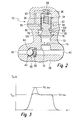
- the exact structure of the Pressure relief valve 56 can be seen in FIG. 2:
- the high pressure pump 30 and the pressure relief valve 56 are housed in a common housing 58. Of the High-pressure pump 30 is only one area in FIG. 2
- the exhaust valve 44 includes a spherical valve element 64, which of a spring 66 is urged against a valve seat 68. Downstream of the exhaust valve 44 is the high pressure fuel line 42 visible. During a suction stroke the delivery chamber 60 opposite the high-pressure fuel line 42 sealed by the outlet valve 44.
- a conical one Extension 76 provided which is cylindrical Valve chamber 80 opens.
- cylindrical Valve chamber 80 opens above the cylindrical Valve chamber 78 cylindrical recess 80 available, which a little has a smaller diameter than the valve chamber 78.
- the cylindrical recess 80 forms a guide for one also cylindrical piston 82. This is below described in detail.
- the elements from the secondary line 70 to the leakage channel 90 are part of the pressure relief valve 56.
- the piston 82 of the pressure relief valve 56 is as follows built up:
- the outlet side section 94 has one circular cylindrical outer contour with constant Diameter. 2 is in the piston 82 from above Blind hole 96 introduced. In this is a spring 98 performed, which is on the one hand on the piston 82 and on the other hand at the bottom of the upper recess 88 in the housing 58 supports. A free edge 100 is formed by this spring 98 of the inlet side section 92 of the piston 82 in FIG. 2 pressed against the conical extension 76. The conical In this respect, extension 76 forms a valve seat.
- the section 94 points toward the outlet side inlet-side section 92 of the piston 82 a Constriction 102 in the form of a rounded, waisted Area.
- a control edge 104 which the separates the two sections 92 and 94 from each other.
- the Control edge 104 is from the free edge 100 of the inlet side Section 92 spaced so that when the free Edge 100 abuts the valve seat 76, the control edge 104 of the annular groove 84 is spaced apart.
- the fuel system 10 with the pressure relief valve 56 works as follows:
- the fuel comes from the electric fuel pump 20 18 from the reservoir 16 into the low pressure fuel line 22 funded.
- the pressure in the Low pressure fuel line 22 is typically about 4 bar.
- the fuel under this pressure is further in the high pressure pump 30 to a system pressure compressed from about 120 bar.
- High pressure pump 30 pressure peaks up to a peak value of about 180 bar occur. Such a pressure peak is shown in Fig. 3 shown in dashed lines. These pressure peaks result from the acceleration of the fuel column in the High pressure fuel line 42 through high pressure pump 30. These pressure peaks are shown in FIG Pressure relief valve 56 in the following manner avoided:
- the pressure peak corresponds to one by the Delivery impulse of the high pressure pump 30 triggered mass flow.
- This mass flow flows into the secondary line 70 through which Flow throttle 74 through into the pre-chamber 72.
- There the mass flow leads to the free edge 100 of the inlet side portion 92 of the piston 82 from the valve seat 78 takes off and the entire piston 82 against Acting force of the spring 98 is moved. This leads to to enlarge the cylindrical valve chamber 78.
- the enlargement of the valve chamber 78 in turn corresponds an alternative volume into which the fuel flows can.
- the fuel flows out the cylindrical valve chamber 78 back into the high pressure fuel line 42 back.
- the piston moves 82 due to the spring action again with his free edge 100 against the valve seat 76.
- the maximum possible escape volume corresponds thus the diameter of the outlet-side section 94 of the Piston 82 multiplied by the maximum distance between the annular groove 84 and the control edge 104.
- the fuel from the bypass 70 can pass through the Flow channel 86 to the inlet side of the high pressure pump 30 flow back.
- This ensures that the System pressure total the allowable value, here for example, 120 bar. So is also if, for example, the quantity control valve 52 fails Safe function of the fuel injection valves 48 guaranteed.
- Through the formation of the inlet side Section 92 of the piston 82 with a constriction 102 ensures that flow forces largely during operation be compensated. Thus there is practically no increase in Opening pressure above the throughput instead. Such a Otherwise, an increase would possibly lead to restrictions in the operation of the fuel system 10 or Run the internal combustion engine when the quantity control valve 52 failed.
Landscapes
- Engineering & Computer Science (AREA)
- Chemical & Material Sciences (AREA)
- Combustion & Propulsion (AREA)
- Mechanical Engineering (AREA)
- General Engineering & Computer Science (AREA)
- Fuel-Injection Apparatus (AREA)
Applications Claiming Priority (2)
| Application Number | Priority Date | Filing Date | Title |
|---|---|---|---|
| DE10118936 | 2001-04-18 | ||
| DE10118936A DE10118936A1 (de) | 2001-04-18 | 2001-04-18 | Druckbegrenzungseinrichtung sowie Kraftstoffsystem mit einer solchen Druckbegrenzungseinrichtung |
Publications (2)
| Publication Number | Publication Date |
|---|---|
| EP1251266A1 true EP1251266A1 (fr) | 2002-10-23 |
| EP1251266B1 EP1251266B1 (fr) | 2005-02-23 |
Family
ID=7681809
Family Applications (1)
| Application Number | Title | Priority Date | Filing Date |
|---|---|---|---|
| EP02005094A Expired - Lifetime EP1251266B1 (fr) | 2001-04-18 | 2002-03-07 | Dispositif de limitation de pression et système de combustible avec tel dispositif de limitation de pression |
Country Status (3)
| Country | Link |
|---|---|
| EP (1) | EP1251266B1 (fr) |
| JP (1) | JP2002332931A (fr) |
| DE (2) | DE10118936A1 (fr) |
Cited By (8)
| Publication number | Priority date | Publication date | Assignee | Title |
|---|---|---|---|---|
| EP1365142A3 (fr) * | 2002-05-24 | 2006-03-15 | Hitachi, Ltd. | Pompe à carburant à haute pression |
| WO2006134264A1 (fr) * | 2005-06-15 | 2006-12-21 | Eaton | Limiteur de pression |
| WO2008122521A1 (fr) * | 2007-04-05 | 2008-10-16 | Continental Automotive Gmbh | Soupape et système d'injection pour un moteur à combustion interne comprenant une soupape |
| WO2012089376A1 (fr) * | 2010-12-27 | 2012-07-05 | Robert Bosch Gmbh | Pompe, notamment pompe d'un système d'injection de carburant |
| WO2012089371A1 (fr) * | 2010-12-27 | 2012-07-05 | Robert Bosch Gmbh | Pompe d'injection pour un système d'injection de carburant |
| WO2012089375A1 (fr) * | 2010-12-27 | 2012-07-05 | Robert Bosch Gmbh | Dispositif de régulation de pression pour un système d'injection de carburant |
| WO2012089370A1 (fr) * | 2010-12-27 | 2012-07-05 | Robert Bosch Gmbh | Conjoncteur-disjoncteur pour un système d'injection de carburant d'un moteur à combustion interne |
| CN102996433A (zh) * | 2012-10-31 | 2013-03-27 | 镇江宝城注浆设备有限公司 | 一种注浆泵安全阀 |
Families Citing this family (6)
| Publication number | Priority date | Publication date | Assignee | Title |
|---|---|---|---|---|
| DE10245084A1 (de) * | 2002-09-27 | 2004-04-01 | Robert Bosch Gmbh | Druckbegrenzungseinrichtung sowie Kraftstoffsystem mit einer solchen Druckbegrenzungseinrichtung |
| DE10327411B4 (de) * | 2002-10-15 | 2015-12-17 | Robert Bosch Gmbh | Druckbegrenzungsventil sowie Kraftstoffsystem mit einem solchen Druckbegrenzungsventil |
| FR2863316B1 (fr) * | 2003-12-04 | 2007-12-28 | Renault Sas | Dispositif d'amortissement d'ondes de pression dans une conduite et installation d'injection de carburant equipee d'un tel dispositif |
| DE102013224387B4 (de) * | 2013-11-28 | 2019-11-28 | Robert Bosch Gmbh | Kraftstoffeinspritzsystem sowie Verfahren zum Betreiben eines Kraftstoffeinspritzsystems |
| DE102014220742B4 (de) | 2014-10-14 | 2021-03-18 | Vitesco Technologies GmbH | Verfahren zum Betreiben eines Kraftstoffversorgungssystems für eine Brennkraftmaschine |
| DE102015215186B3 (de) | 2015-08-10 | 2016-12-15 | Continental Automotive Gmbh | Kraftstoffhochdruckpumpe |
Citations (7)
| Publication number | Priority date | Publication date | Assignee | Title |
|---|---|---|---|---|
| DE3912106A1 (de) * | 1988-05-02 | 1989-11-16 | Volkswagen Ag | Kraftstoffeinspritzeinrichtung |
| JPH0688557A (ja) * | 1992-07-24 | 1994-03-29 | Nippondenso Co Ltd | 電磁制御式燃料噴射装置 |
| US5353766A (en) * | 1993-09-08 | 1994-10-11 | Cummins Engine Company, Inc. | Distributor for a high pressure fuel system |
| JPH09242639A (ja) * | 1996-03-08 | 1997-09-16 | Denso Corp | 蓄圧式燃料噴射装置 |
| DE19612412A1 (de) * | 1996-03-28 | 1997-10-02 | Rexroth Mannesmann Gmbh | Regelung für ein Druckfluid-Versorgungssystem, insbesondere für den Hochdruck in einem Kraftstoff-Einspritzsystem |
| EP0887544A1 (fr) * | 1997-06-27 | 1998-12-30 | Robert Bosch Gmbh | Système d'injection de combustible pour moteurs à combustion interne |
| WO1999060266A1 (fr) * | 1998-05-20 | 1999-11-25 | Robert Bosch Gmbh | Soupape de limitation de pression |
Family Cites Families (4)
| Publication number | Priority date | Publication date | Assignee | Title |
|---|---|---|---|---|
| DE1203991B (de) * | 1963-06-27 | 1965-10-28 | Bosch Gmbh Robert | Druckregelventil |
| DE19546839C2 (de) * | 1995-12-15 | 2000-04-20 | Deutz Ag | Druckhaltevorrichtung |
| DE19852409A1 (de) * | 1998-11-13 | 2000-05-18 | Hydraulik Ring Gmbh | Druckbegrenzungsventil, insbesondere für Fahrzeuge |
| DE19933198A1 (de) * | 1999-07-15 | 2001-01-18 | Fev Motorentech Gmbh | Verfahren zur Druckregelung an einer Einspritzvorrichtung für flüssige Kraftstoffe |
-
2001
- 2001-04-18 DE DE10118936A patent/DE10118936A1/de not_active Ceased
-
2002
- 2002-03-07 EP EP02005094A patent/EP1251266B1/fr not_active Expired - Lifetime
- 2002-03-07 DE DE50202302T patent/DE50202302D1/de not_active Expired - Lifetime
- 2002-04-17 JP JP2002115016A patent/JP2002332931A/ja active Pending
Patent Citations (7)
| Publication number | Priority date | Publication date | Assignee | Title |
|---|---|---|---|---|
| DE3912106A1 (de) * | 1988-05-02 | 1989-11-16 | Volkswagen Ag | Kraftstoffeinspritzeinrichtung |
| JPH0688557A (ja) * | 1992-07-24 | 1994-03-29 | Nippondenso Co Ltd | 電磁制御式燃料噴射装置 |
| US5353766A (en) * | 1993-09-08 | 1994-10-11 | Cummins Engine Company, Inc. | Distributor for a high pressure fuel system |
| JPH09242639A (ja) * | 1996-03-08 | 1997-09-16 | Denso Corp | 蓄圧式燃料噴射装置 |
| DE19612412A1 (de) * | 1996-03-28 | 1997-10-02 | Rexroth Mannesmann Gmbh | Regelung für ein Druckfluid-Versorgungssystem, insbesondere für den Hochdruck in einem Kraftstoff-Einspritzsystem |
| EP0887544A1 (fr) * | 1997-06-27 | 1998-12-30 | Robert Bosch Gmbh | Système d'injection de combustible pour moteurs à combustion interne |
| WO1999060266A1 (fr) * | 1998-05-20 | 1999-11-25 | Robert Bosch Gmbh | Soupape de limitation de pression |
Non-Patent Citations (2)
| Title |
|---|
| PATENT ABSTRACTS OF JAPAN vol. 018, no. 352 (M - 1631) 4 July 1994 (1994-07-04) * |
| PATENT ABSTRACTS OF JAPAN vol. 1998, no. 01 30 January 1998 (1998-01-30) * |
Cited By (12)
| Publication number | Priority date | Publication date | Assignee | Title |
|---|---|---|---|---|
| EP1365142A3 (fr) * | 2002-05-24 | 2006-03-15 | Hitachi, Ltd. | Pompe à carburant à haute pression |
| US7152583B2 (en) | 2002-05-24 | 2006-12-26 | Hitachi, Ltd. | High-pressure fuel pump |
| EP1835169A3 (fr) * | 2002-05-24 | 2007-09-26 | Hitachi, Ltd. | Pompe à carburant à haute pression |
| WO2006134264A1 (fr) * | 2005-06-15 | 2006-12-21 | Eaton | Limiteur de pression |
| FR2887319A1 (fr) * | 2005-06-15 | 2006-12-22 | Eaton Sa Monegasque | Limiteur de pression |
| US8245725B2 (en) * | 2005-06-15 | 2012-08-21 | Borgwarner Inc. | Pressure relief device |
| WO2008122521A1 (fr) * | 2007-04-05 | 2008-10-16 | Continental Automotive Gmbh | Soupape et système d'injection pour un moteur à combustion interne comprenant une soupape |
| WO2012089376A1 (fr) * | 2010-12-27 | 2012-07-05 | Robert Bosch Gmbh | Pompe, notamment pompe d'un système d'injection de carburant |
| WO2012089371A1 (fr) * | 2010-12-27 | 2012-07-05 | Robert Bosch Gmbh | Pompe d'injection pour un système d'injection de carburant |
| WO2012089375A1 (fr) * | 2010-12-27 | 2012-07-05 | Robert Bosch Gmbh | Dispositif de régulation de pression pour un système d'injection de carburant |
| WO2012089370A1 (fr) * | 2010-12-27 | 2012-07-05 | Robert Bosch Gmbh | Conjoncteur-disjoncteur pour un système d'injection de carburant d'un moteur à combustion interne |
| CN102996433A (zh) * | 2012-10-31 | 2013-03-27 | 镇江宝城注浆设备有限公司 | 一种注浆泵安全阀 |
Also Published As
| Publication number | Publication date |
|---|---|
| JP2002332931A (ja) | 2002-11-22 |
| DE10118936A1 (de) | 2002-11-07 |
| EP1251266B1 (fr) | 2005-02-23 |
| DE50202302D1 (de) | 2005-03-31 |
Similar Documents
| Publication | Publication Date | Title |
|---|---|---|
| DE102004013307B4 (de) | Kraftstoffhochdruckpumpe mit einem Druckbegrenzungsventil | |
| EP1411238B1 (fr) | Soupape de limitation de pression pour un système d'injection de carburant | |
| EP2273115B1 (fr) | Pompe à fluide, en particulier pompe à carburant haute pression, avec amortisseur de pression | |
| DE10327411B4 (de) | Druckbegrenzungsventil sowie Kraftstoffsystem mit einem solchen Druckbegrenzungsventil | |
| EP1247977A1 (fr) | Système d'alimentation en carburant | |
| EP1654456B1 (fr) | Dispositif d'injection de carburant pour moteur a combustion interne | |
| EP0801710B1 (fr) | Dispositif d'injection de carburant pour moteurs a combustion interne | |
| DE102006013703A1 (de) | Kraftstoffpumpe | |
| EP1251266A1 (fr) | Dispositif de limitation de pression et système de combustible avec tel dispositif de limitation de pression | |
| DE102005033638A1 (de) | Kraftstoff-Fördereinrichtung, insbesondere für eine Brennkraftmaschine | |
| EP1342005B1 (fr) | Systeme d'injection de carburant pour moteurs a combustion interne | |
| EP2670971A2 (fr) | Unité pompe pour une pompe haute pression | |
| DE10139054C1 (de) | Verfahren, Computerprogramm, Steuer- und/oder Regelgerät sowie Kraftstoffsystem für eine Brennkraftmaschine, insbesondere mit Direkteinspritzung | |
| DE19846157A1 (de) | Pumpenanordnung zur Kraftstoffhochdruckerzeugung | |
| EP1141539B1 (fr) | Pompe a piston pour carburant sous haute pression | |
| EP1403509B1 (fr) | Dispositif de limitation de pression et système de combustible avec tel dispositif de limitation de pression | |
| DE10139052A1 (de) | Verfahren zum Betreiben einer Brennkraftmaschine, insbesondere mit Direkteinspritzung, Computerprogramm, Steuer- und/oder Regelgerät, sowie Kraftstoffsystem für eine Brennkraftmaschine | |
| EP1298379B1 (fr) | Dispositif pour amortir les pulsations de pression dans un système à fluide, en particulier dans un système à carburant d'un moteur à combustion, et système à carburant | |
| EP1395753B1 (fr) | Pompe haute pression pour un systeme de carburant d'un moteur a combustion interne | |
| DE10139055A1 (de) | Verfahren, Computerprogramm, Steuer- und/oder Regelgerät sowie Kraftstoffsystem für eine Brennkraftmaschine | |
| DE10154133C1 (de) | Kraftstoffsystem | |
| DE10220281A1 (de) | Kraftstoffpumpe, insbesondere für eine Brennkraftmaschine mit Direkteinspritzung | |
| DE19902259A1 (de) | Montageverfahren | |
| DE102011089964A1 (de) | Drucksteuerventil für ein Kraftstoffeinspritzsystem sowie Kraftstoffeinspritzsystem | |
| DE102008041393A1 (de) | Kraftstoffsystem für eine Brennkraftmaschine |
Legal Events
| Date | Code | Title | Description |
|---|---|---|---|
| PUAI | Public reference made under article 153(3) epc to a published international application that has entered the european phase |
Free format text: ORIGINAL CODE: 0009012 |
|
| AK | Designated contracting states |
Kind code of ref document: A1 Designated state(s): AT BE CH CY DE DK ES FI FR GB GR IE IT LI LU MC NL PT SE TR |
|
| AX | Request for extension of the european patent |
Free format text: AL;LT;LV;MK;RO;SI |
|
| 17P | Request for examination filed |
Effective date: 20030423 |
|
| AKX | Designation fees paid |
Designated state(s): DE FR GB IT |
|
| 17Q | First examination report despatched |
Effective date: 20031113 |
|
| GRAP | Despatch of communication of intention to grant a patent |
Free format text: ORIGINAL CODE: EPIDOSNIGR1 |
|
| GRAS | Grant fee paid |
Free format text: ORIGINAL CODE: EPIDOSNIGR3 |
|
| GRAA | (expected) grant |
Free format text: ORIGINAL CODE: 0009210 |
|
| AK | Designated contracting states |
Kind code of ref document: B1 Designated state(s): DE FR GB IT |
|
| PG25 | Lapsed in a contracting state [announced via postgrant information from national office to epo] |
Ref country code: IT Free format text: LAPSE BECAUSE OF FAILURE TO SUBMIT A TRANSLATION OF THE DESCRIPTION OR TO PAY THE FEE WITHIN THE PRESCRIBED TIME-LIMIT;WARNING: LAPSES OF ITALIAN PATENTS WITH EFFECTIVE DATE BEFORE 2007 MAY HAVE OCCURRED AT ANY TIME BEFORE 2007. THE CORRECT EFFECTIVE DATE MAY BE DIFFERENT FROM THE ONE RECORDED. Effective date: 20050223 Ref country code: FR Free format text: LAPSE BECAUSE OF NON-PAYMENT OF DUE FEES Effective date: 20050223 Ref country code: GB Free format text: LAPSE BECAUSE OF FAILURE TO SUBMIT A TRANSLATION OF THE DESCRIPTION OR TO PAY THE FEE WITHIN THE PRESCRIBED TIME-LIMIT Effective date: 20050223 |
|
| REG | Reference to a national code |
Ref country code: GB Ref legal event code: FG4D Free format text: NOT ENGLISH |
|
| REG | Reference to a national code |
Ref country code: IE Ref legal event code: FG4D Free format text: GERMAN |
|
| REF | Corresponds to: |
Ref document number: 50202302 Country of ref document: DE Date of ref document: 20050331 Kind code of ref document: P |
|
| GBV | Gb: ep patent (uk) treated as always having been void in accordance with gb section 77(7)/1977 [no translation filed] |
Effective date: 20050223 |
|
| PLBE | No opposition filed within time limit |
Free format text: ORIGINAL CODE: 0009261 |
|
| STAA | Information on the status of an ep patent application or granted ep patent |
Free format text: STATUS: NO OPPOSITION FILED WITHIN TIME LIMIT |
|
| 26N | No opposition filed |
Effective date: 20051124 |
|
| EN | Fr: translation not filed | ||
| PGFP | Annual fee paid to national office [announced via postgrant information from national office to epo] |
Ref country code: DE Payment date: 20110525 Year of fee payment: 10 |
|
| REG | Reference to a national code |
Ref country code: DE Ref legal event code: R119 Ref document number: 50202302 Country of ref document: DE Effective date: 20121002 |
|
| PG25 | Lapsed in a contracting state [announced via postgrant information from national office to epo] |
Ref country code: DE Free format text: LAPSE BECAUSE OF NON-PAYMENT OF DUE FEES Effective date: 20121002 |