EP1251264A2 - Vorrichtung zur Aufbereitung von Kraftstoffen - Google Patents
Vorrichtung zur Aufbereitung von Kraftstoffen Download PDFInfo
- Publication number
- EP1251264A2 EP1251264A2 EP02002678A EP02002678A EP1251264A2 EP 1251264 A2 EP1251264 A2 EP 1251264A2 EP 02002678 A EP02002678 A EP 02002678A EP 02002678 A EP02002678 A EP 02002678A EP 1251264 A2 EP1251264 A2 EP 1251264A2
- Authority
- EP
- European Patent Office
- Prior art keywords
- fuel
- tube
- line
- magnets
- fuels according
- Prior art date
- Legal status (The legal status is an assumption and is not a legal conclusion. Google has not performed a legal analysis and makes no representation as to the accuracy of the status listed.)
- Granted
Links
- 239000000446 fuel Substances 0.000 title claims abstract description 102
- 229930195733 hydrocarbon Natural products 0.000 claims abstract description 5
- 150000002430 hydrocarbons Chemical class 0.000 claims abstract description 5
- 230000005291 magnetic effect Effects 0.000 claims description 41
- 238000004804 winding Methods 0.000 claims description 20
- 238000012545 processing Methods 0.000 claims description 15
- 238000002485 combustion reaction Methods 0.000 claims description 10
- 238000002360 preparation method Methods 0.000 claims description 3
- 230000001427 coherent effect Effects 0.000 claims description 2
- 238000010304 firing Methods 0.000 claims description 2
- 239000004215 Carbon black (E152) Substances 0.000 abstract 2
- 230000005415 magnetization Effects 0.000 description 8
- 244000089486 Phragmites australis subsp australis Species 0.000 description 7
- 239000003344 environmental pollutant Substances 0.000 description 7
- 231100000719 pollutant Toxicity 0.000 description 7
- 230000009467 reduction Effects 0.000 description 4
- 230000003993 interaction Effects 0.000 description 3
- 238000005259 measurement Methods 0.000 description 3
- 239000000126 substance Substances 0.000 description 3
- 230000009471 action Effects 0.000 description 2
- 230000008901 benefit Effects 0.000 description 2
- 238000013461 design Methods 0.000 description 2
- 238000012549 training Methods 0.000 description 2
- 230000002730 additional effect Effects 0.000 description 1
- 239000010426 asphalt Substances 0.000 description 1
- 230000008859 change Effects 0.000 description 1
- 238000006243 chemical reaction Methods 0.000 description 1
- 238000011109 contamination Methods 0.000 description 1
- 230000003111 delayed effect Effects 0.000 description 1
- 238000011161 development Methods 0.000 description 1
- 238000010586 diagram Methods 0.000 description 1
- 239000006185 dispersion Substances 0.000 description 1
- 230000000694 effects Effects 0.000 description 1
- 230000005611 electricity Effects 0.000 description 1
- 238000002474 experimental method Methods 0.000 description 1
- 230000002349 favourable effect Effects 0.000 description 1
- 230000005294 ferromagnetic effect Effects 0.000 description 1
- 230000004907 flux Effects 0.000 description 1
- 230000006872 improvement Effects 0.000 description 1
- 238000000034 method Methods 0.000 description 1
- 238000012986 modification Methods 0.000 description 1
- 230000004048 modification Effects 0.000 description 1
- 230000008569 process Effects 0.000 description 1
- 239000007787 solid Substances 0.000 description 1
- 230000002195 synergetic effect Effects 0.000 description 1
Images

Classifications
-
- C—CHEMISTRY; METALLURGY
- C10—PETROLEUM, GAS OR COKE INDUSTRIES; TECHNICAL GASES CONTAINING CARBON MONOXIDE; FUELS; LUBRICANTS; PEAT
- C10G—CRACKING HYDROCARBON OILS; PRODUCTION OF LIQUID HYDROCARBON MIXTURES, e.g. BY DESTRUCTIVE HYDROGENATION, OLIGOMERISATION, POLYMERISATION; RECOVERY OF HYDROCARBON OILS FROM OIL-SHALE, OIL-SAND, OR GASES; REFINING MIXTURES MAINLY CONSISTING OF HYDROCARBONS; REFORMING OF NAPHTHA; MINERAL WAXES
- C10G32/00—Refining of hydrocarbon oils by electric or magnetic means, by irradiation, or by using microorganisms
- C10G32/02—Refining of hydrocarbon oils by electric or magnetic means, by irradiation, or by using microorganisms by electric or magnetic means
-
- F—MECHANICAL ENGINEERING; LIGHTING; HEATING; WEAPONS; BLASTING
- F02—COMBUSTION ENGINES; HOT-GAS OR COMBUSTION-PRODUCT ENGINE PLANTS
- F02M—SUPPLYING COMBUSTION ENGINES IN GENERAL WITH COMBUSTIBLE MIXTURES OR CONSTITUENTS THEREOF
- F02M27/00—Apparatus for treating combustion-air, fuel, or fuel-air mixture, by catalysts, electric means, magnetism, rays, sound waves, or the like
- F02M27/04—Apparatus for treating combustion-air, fuel, or fuel-air mixture, by catalysts, electric means, magnetism, rays, sound waves, or the like by electric means, ionisation, polarisation or magnetism
- F02M27/045—Apparatus for treating combustion-air, fuel, or fuel-air mixture, by catalysts, electric means, magnetism, rays, sound waves, or the like by electric means, ionisation, polarisation or magnetism by permanent magnets
-
- F—MECHANICAL ENGINEERING; LIGHTING; HEATING; WEAPONS; BLASTING
- F02—COMBUSTION ENGINES; HOT-GAS OR COMBUSTION-PRODUCT ENGINE PLANTS
- F02B—INTERNAL-COMBUSTION PISTON ENGINES; COMBUSTION ENGINES IN GENERAL
- F02B3/00—Engines characterised by air compression and subsequent fuel addition
- F02B3/06—Engines characterised by air compression and subsequent fuel addition with compression ignition
Definitions
- the invention relates to a device for processing fuels, preferably hydrocarbons, for internal combustion engines or firing systems with at least one magnet, one in the magnetic field provided fuel line and a supply and discharge of the Fuel.
- DE 299 14 247 A1 discloses a device in which the fuel through a comparatively narrow gap of a ferromagnetic Kerns is headed.
- a disadvantage of these devices is that that the interaction time between magnetic field and fuel is comparatively small. Because of the relatively low magnetization fuel savings and the reduction of harmful exhaust gas components also drop not optimal.
- the device also has similarly short interaction times according to DE 30 50 645 A1, in which the magnetization of the fuel by a field lying parallel to the direction of flow of the fuel annular permanent magnet, and the device according to DE 197 32nd 834 A1, in which the fuel passes through the interior of one or more current-carrying coils is steered.
- the invention has the task provided, a device for processing the fuel with the help of magnetic fields indicate with which the magnetization of the fuel improves and thereby fuel consumption and pollutant emissions is further reduced, the device without expensive conversion work can be integrated into any combustion system.
- the proposed device has two different tubes Diameter, which are arranged concentrically to each other.
- Both Pipes carry pipe magnets with a polarity pointing in the pipe axis, whereby the magnets equally as permanent magnets or as electromagnets can be trained.
- Two each on the outer and inner Pipe magnets each form a pair, its partner are arranged in the same position with respect to the axis direction. The in the axial direction as well as in the radial direction adjacent magnets are poled differently.
- Both pipes close one or more gaps between them a, which receive the line for the supply of fuel while the line for the discharge of the fuel is arranged inside the inner tube is. It is essential to the invention that the line for the feed is passed through the device several times in the axial direction.
- the chosen arrangement of the magnets means that there are gaps in the gaps between both tubes and inside the inner tube Form magnetic fields, with the contribution of the inner and outer Magnets of a pair to the magnetic field in the gaps each is rectified.
- the magnetization of the Fuel not only the strength of the magnetic field, but also the length of stay of fuel within the magnetic field is important.
- the present invention passes through the line for supplying the fuel hence the arrangement several times in the axial direction and expands inside the inner tube to a larger diameter, the Value preferably corresponds to that of the cross section of the inner tube. Both measures ensure that the fuel meets the magnetic field exposed much longer than in known devices. In the first-mentioned measure, the longer stay due to the longer path within the magnetic field, with the second Measure due to the delayed flow of fuel reached within the magnetic field present in this area.
- the cross-section of the line for the discharge corresponds to (2xm) times the cross-section of the line for the feed.
- This specification of the cross sections causes the fuel to drain inside inside Tube just as long as it is exposed to the present magnetic field when feeding on its (2xm) -fold pass in the axial direction through the arrangement.
- the device according to the present invention can advantageously be used in any Combustion system can be used.
- These include internal combustion engines, such as 2-stroke, 4-stroke, petrol or diesel engines, as well as jet engines or also combustion plants.
- To install the proposed Devices in the above-mentioned combustion systems are not complex Modifications to the systems themselves required.
- Variants of the aforementioned embodiments are electromagnetic Equipped coils, each having a cylindrical bobbin.
- the coil ends are connected to the electrical poles of the vehicle battery, wherein the electrical polarity is selected so that the adjacent coils each flow of electricity in opposite directions.
- the design of the Tubular magnets as electromagnets have the advantage that the current strength and thus the magnetic field strength generated within the coils in a wide range Borders is changeable.
- the magnetization of the by the magnetic field directed fuel can thus also be variably specified. This flexibility is used in the event of fluctuating fuel throughput in such a way that the current strength is chosen proportional to the throughput, so that the magnetization per unit volume of fuel remains constant.
- the current flow through the coils can also be specified in the form of a clocked direct current. Like practice has shown, significantly increased fuel savings are achieved as a result.
- a particularly preferred embodiment of solution one of the invention Device has tubes with a square cross section of different sizes that are concentric with each other and 45 degrees are arranged rotated against each other around the pipe axis.
- the Cross sections preferably chosen so that the diagonal of the cross section of the inner tube including those applied to the tube Magnets is slightly smaller than the inside diameter of the outer tube.
- the Intermediate spaces between the two tubes then fill each Space in the corner areas of the outer tube and point each a cross section from the shape of a triangle. In the field of magnet pairs these spaces are in the same direction from Magnetic flux penetrates the outer and inner coils.
- the feed line of fuel is looped through each of the four spaces that Feed line thus passes through the arrangement four times in the axial direction. This compares the length of time the fuel stays in the magnetic field a single pass also increased to four times the amount and the magnetization of the fuel is improved accordingly.
- This solution is also based on a device for processing Fuels with at least one magnet and one provided in the magnetic field Fuel line off.
- the device is a first tube containing one or more electromagnets each with a cylindrical bobbin.
- the windings of the coils are each designed so that the winding wire from layer to layer has a different direction.
- four are different A distinction is made between types of wraps that change from one layer to the next.
- the different directions of the winding wire lead under current flow in the inner area of the tube with an inhomogeneous magnetic field complicated course, which changes strongly at short distances Directions. In this excellent area of the magnetic field the line for the discharge of the fuel is arranged.
- An essential finding with this solution relates to the one proposed Type of winding generated special magnetic field. As shown in practice this field unfolds compared to that in the first part of the description device with homogeneous fields a higher effectiveness in an effort to reduce fuel consumption and To minimize pollutant emissions.
- the increased effectiveness of the second solution according to the present invention is based on the fact that the fuel inside numerous small magnetic fields in close succession of the discharge line different orientation. If you wanted a homogeneous one Magnetic field according to the first solution a comparable effectiveness to achieve this, the fuel would have to be routed in a large number of lines repeatedly through the homogeneous magnetic field. This On the other hand, the solution advantageously provides a one-off Passage of the fuel through the specially trained magnetic field high effectiveness.
- a second pipe concentric with the first pipe, which surrounds the first tube and its magnets.
- the second pipe is too equipped with one or more magnets of the type described. there are the cross sections of the tubes and the dimensions of the magnets chosen so that a free space remains between the two tubes.
- This gap has a similarly complicated magnetic field as the inner area of the first tube.
- the fuel is supplied in this case, as with the first solution, through the one between the two pipes lying space while the pipe for the drainage through leads the inner area of the first tube.
- the feeders looped through the magnetic field several times, causing the Dwell time of the fuel within the inhomogeneous magnetic field increases and thereby the effectiveness of the device is higher than with one pass of the fuel through the inhomogeneous magnetic fields.
- the cross sections of the tubes can in principle have different shapes. Preferred in the embodiments according to the solution two training courses in which the cross sections of the pipes and the Tubes arranged coils each an equilateral polygon, for example a triangle, square, pentagon, etc., or a circle.
- Particularly preferred versions of solution one and two have Fuel lines on which also the lines for the discharge of the Fuel loops several times through the interior of the interior or the first tube are guided.
- This constructive measure leads analogous to the version with two pipes, in which the feed line is looped several times through the spaces between the two pipes, to a large residence time of the fuel in the discharge line and accordingly to an intensive interaction of the fuel with the inhomogeneous magnetic field.
- the advantageous consequence is also in this case increased efficiency in fuel saving and reduction of pollutant emissions.
- the inner region has of the inner or the first tube a plurality of longitudinal channels, or is equipped with a further tube having several longitudinal channels. There are two channels on the front side by means of connecting pieces connected so that the interconnected channels total form a coherent, loop-shaped line that is used for discharge of the fuel is used. The effect of this loop-shaped Channels in the passage of the fuel corresponds to that of the aforementioned Embodiment.
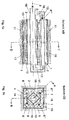
- the illustration shows an embodiment with square tubes different Size, whereby the outer tube with the reference number 1, the inner tube is identified by reference number 2. Both pipes are concentric to axis 3 and 45 degrees to each other around the pipe axis twisted arranged. Through this training they receive Intermediate spaces 4, 5, 6, 7 lying between the two tubes each have one Cross section of the shape of a triangle. Take spaces 4 - 7 the line 8, 8 ', 8 ", 8"' for the supply of fuel.
- the same Number is intended to indicate that there are four sections in and the same line, which the present arrangement four times in passes in the axial direction.
- the tubes 1 and 2 are each equipped with two coils 10 and 11 or 12 and 13, where the opposite on the outer and inner tube Coils 10 and 12 or 11 and 13 with respect to the axial direction take the same position.
- the coil ends are connected to the electrical poles of the vehicle battery.
- the Polarities as indicated by the symbols (+), (-), selected so that each Current flows through adjacent coils in opposite directions become.
- the contribution of the inner and outer Magnets 10 and 12 or 11 and 13 of a pair to the magnetic field in the Spaces 4-7 each rectified.
- the arrows 15 and 17 shown in dashed lines are an indication that the associated connectors below the Laying plane, the solid arrows 14 and 16 are a hint ensure that the corresponding connectors are above the drawing level lie. Due to this design of the feed line penetrated the fuel is the magnetic field present in the spaces 4 -7 a total of four times in the direction of the magnetic lines.
- the fuel line opens via the connector indicated by arrow 17 finally in line 18 for the discharge of the fuel on.
- This line is aligned and penetrated concentrically to axis 3 the magnetic field generated inside the coils 12 and 13 in the direction of Magnetic lines.
- the direction of flow of the fuel in this area of the line points out of the drawing layer.
- the cross section is this line section is larger than that of sections 8 - 8 "' In the present embodiment, the ratio of the two cross sections is preferred 4 selected.
- FIG. 2 shows the top view of a coil 20 of an electromagnet Solution two reproduced in a very simplified representation.
- the individual representations in FIGS. 2a, 2b, 2c, 2d each show a layer 21, 22, 23, 24 with one of the four provided according to the invention Types of wraps 21 ', 22', 23 ', 24'.
- the order of those provided on a spool 20 Layers correspond to the order of FIGS. 2a, 2b, 2c, 2d, with four layers in each case on a layer with winding type 24 ' connect with the shown winding types.
- the winding diagram shown leads through the turns when there is a current flow inside 29 of coil 20 to form an inhomogeneous magnetic field strongly changing field directions.
- the line 30 is for the removal of the fuel is provided.
- the proposed arrangement of magnets and fuel line leads to the fact that the fuel is exposed to the magnetic field for much longer than in known devices.
- the increase in the length of stay by repeatedly looping through the feed lines and / or the Discharge lines and / or a delay in the flow rate of the Fuel in the discharge line reached.
- the result is magnetization of the fuel improves and thereby the fuel consumption and reduces pollutant emissions.
Landscapes
- Chemical & Material Sciences (AREA)
- Engineering & Computer Science (AREA)
- Oil, Petroleum & Natural Gas (AREA)
- Chemical Kinetics & Catalysis (AREA)
- Microbiology (AREA)
- General Chemical & Material Sciences (AREA)
- Life Sciences & Earth Sciences (AREA)
- Organic Chemistry (AREA)
- Combustion & Propulsion (AREA)
- Mechanical Engineering (AREA)
- General Engineering & Computer Science (AREA)
- Production Of Liquid Hydrocarbon Mixture For Refining Petroleum (AREA)
- Feeding And Controlling Fuel (AREA)
- Crystals, And After-Treatments Of Crystals (AREA)
Abstract
Description
- 2x(n+1) Rohrmagnete mit einer in Richtung der Rohrachse weisenden Polung vorgesehen sind, wobei n durch eine natürliche Zahl gegeben ist,
- von denen jeweils (n+1) Magnete in axialer Richtung nebeneinander
auf einem inneren und einem zum inneren Rohr konzentrischen
äußeren Rohr angeordnet sind,
- wobei die auf dem äußeren und inneren Rohr angeordneten Magnete jeweils paarweise die gleiche Position in axialer Richtung einnehmen,
- und in axialer Richtung als auch in radialer Richtung jeweils benachbarte Magnete gegensinnig gepolt sind,
- die Zuführung des Kraftstoffs im Zwischenraum zwischen beiden Rohren
erfolgt,
- und die Leitung für die Zuführung die axiale Richtung vorzugsweise 2xm mal durchläuft, wobei m durch eine natürliche Zahl gegeben ist,
- die Abführung des Kraftstoffs im Inneren des inneren Rohrs erfolgt,
- wobei der Durchmesser der Leitung für die Abführung größer als der für die Zuführung, vorzugsweise gleich dem Durchmesser des inneren Rohrs, ist.
- ein erstes Rohr zur Anwendung kommt,
- auf dem ein oder mehrere Elektromagnete mit jeweils zylindrischem Spulenkörper angeordnet sind,
- die Spulen der Elektromagnete jeweils in vier aufeinander folgenden
Lagen unterschiedliche Wickelart aufweisen, wobei
- eine erste Lage in Umfangsrichtung
- eine zweite Lage mäanderförmig in Richtung der Mantellinien
- eine dritte Lage mänderförmig in Richtung von auf der Mantelfläche liegenden Wendellinien großer Steigung und positivem Steigungsmaß
- eine vierte Lage mänderförmig in Richtung von auf der Mantelfläche liegenden Wendellinien großer Steigung und negativem Steigungsmaß gewickelt ist
- und die Abführung des Kraftstoffs im Inneren des ersten Rohres erfolgt.
- entweder in Richtung der Mantellinien
- oder in Richtung von auf der Mantelfläche liegenden Wendellinien großer Steigung und positivem Steigungsmaß
- oder in Richtung von auf der Mantelfläche liegenden Wendellinien großer Steigung und negativem Steigungsmaß
- Figur 1a:
- Längsschnitt durch die erfindungsgemäße Vorrichtung mit der in Fig. 1 b angedeuteten Schnittführung AB.
- Figur 1b:
- Querschnitt durch die Vorrichtung entlang des in Fig. 1a angedeuteten Schnittes CD.
- Figur 2a - 2d:
- je eine Aufsicht auf die nach unterschiedlichen Wikkelarten gewickelten Lagen der Elektromagnete
- entweder in Richtung der Mantellinien (22')
- oder in Richtung von auf der Mantelfläche liegenden Wendellinien 27 großer Steigung und positivem Steigungsmaß (23')
- oder in Richtung von auf der Mantelfläche liegenden Wendellinien 28 großer Steigung und negativem Steigungsmaß (24')
Claims (14)
- Vorrichtung zur Aufbereitung von Kraftstoffen, vorzugsweise Kohlenwasserstoffen, für Verbrennungsmaschinen oder Feuerungsanlagen mit wenigstens einem Magneten, einer im Magnetfeld vorgesehenen Kraftstoffleitung und einer Zu- und Abführung des Kraftstoffs, dadurch gekennzeichnet, daß2x(n+1) Rohrmagnete (10 - 13) mit einer in Richtung der Rohrachse (3) weisenden Polung vorgesehen sind, wobei n durch eine natürliche Zahl gegeben ist,von denen jeweils (n+1) Magnete (10, 11 bzw. 12, 13) in axialer Richtung nebeneinander auf einem inneren (2) und einem zum inneren Rohr konzentrischen äußeren (1) Rohr angeordnet sind,wobei die auf dem äußeren (1) und inneren (2) Rohr angeordneten Magnete (10 - 13) jeweils paarweise die gleiche Position in axialer Richtung einnehmen,und in axialer Richtung als auch in radialer Richtung jeweils benachbarte Magnete gegensinnig gepolt sind,die Zuführung des Kraftstoffs im Zwischenraum (4 - 7) zwischen beiden Rohren (1, 2) erfolgt,und die Leitung für die Zuführung (8 - 8"') die axiale Richtung vorzugsweise 2xm mal durchläuft, wobei m durch eine natürliche Zahl gegeben ist,die Abführung des Kraftstoffs im Inneren des inneren Rohrs (2) erfolgt,wobei der Durchmesser der Leitung für die Abführung (18) größer als der für die Zuführung (8 - 8"'), vorzugsweise gleich dem Durchmesser des inneren Rohrs (2), ist.
- Vorrichtung zur Aufbereitung von Kraftstoffen nach Anspruch 1, dadurch gekennzeichnet, daß der Querschnitt der Leitung für die Abführung (18) dem (2xm)-fachen des Querschnitts der Leitung für die Zuführung (8 - 8"') entspricht.
- Vorrichtung zur Aufbereitung von Kraftstoffen nach Anspruch 1 oder 2,
dadurch gekennzeichnet, daß n = 1 ist, die Anzahl der Rohrmagnete (10 - 13) somit vier beträgt. - Vorrichtung zur Aufbereitung von Kraftstoffen nach einem der Ansprüche 1 - 3, dadurch gekennzeichnet, daß die Rohrmagnete elektromagnetische Spulen (10 - 13) mit zylindrischem Spulenkörper sind.
- Vorrichtung zur Aufbereitung von Kraftstoffen nach Anspruch 4, dadurch gekennzeichnet, daß zusätzliche Drähte quer zum Drahtverlauf der Spule angeordnet sind.
- Vorrichtung zur Aufbereitung von Kraftstoffen nach Anspruch 4 oder 5, dadurch gekennzeichnet, daß durch die Spulen (10 - 13) und/oder die zusätzlichen Drähte ein konstanter und/oder getakteter Gleichstrom fließt.
- Vorrichtung zur Aufbereitung von Kraftstoffen nach einem der Ansprüche 1 - 6, dadurch gekennzeichnet, daß die beiden Rohre (1, 2) jeweils einen quadratischen Querschnitt aufweisen und um 45 Grad um die Rohrachse gegeneinander verdreht angeordnet sind.
- Vorrichtung zur Aufbereitung von Kraftstoffen nach Anspruch 7, dadurch gekennzeichnet, daß m = 2 ist, somit die Leitung für die Zuführung (8 - 8"') die axiale Richtung vier mal durchläuft.
- Vorrichtung zur Aufbereitung von Kraftstoffen, vorzugsweise Kohlenwasserstoffen, für Verbrennungsmaschinen oder Feuerungsanlagen mit wenigstens einem Magneten, einer im Magnetfeld vorgesehenen Kraftstoff leitung und einer Zu- und Abführung des Kraftstoffs,
dadurch gekennzeichnet, daßein erstes Rohr vorgesehen ist,auf dem ein oder mehrere Elektromagnete mit jeweils zylindrischem Spulenkörper angeordnet sind,die Spulen (20) der Elektromagnete jeweils in vier aufeinander folgenden Lagen (21 - 24)unterschiedliche Wickelart (21' - 24') aufweisen, wobeieine erste Lage (21) in Umfangsrichtung,eine zweite Lage (22) mäanderförmig in Richtung der Mantellinien (25),eine dritte Lage (23) mänderförmig in Richtung von auf der Mantelfläche liegenden Wendellinien (27) großer Steigung und positivem Steigungsmaß,eine vierte Lage (24) mänderförmig in Richtung von auf der Mantelfläche liegenden Wendellinien (28) großer Steigung und negativem Steigungsmaß gewickelt istund die Abführung (30) des Kraftstoffs im Inneren (29) des ersten Rohres erfolgt. - Vorrichtung zur Aufbereitung von Kraftstoffen nach Anspruch 9, dadurch gekennzeichnet, daßdas erste Rohr und dessen Magnete von einem konzentrisch ausgerichteten zweiten Rohr umgeben ist,auf dem jeweils ein oder mehrere der genannten Elektromagnete angeordnet sindund die Zuführung des Kraftstoffs durch den zwischen beiden Rohren liegenden Zwischenraum erfolgt.
- Vorrichtung zur Aufbereitung von Kraftstoffen nach Anspruch 9 oder 10,
dadurch gekennzeichnet, daßdie Spulenkörper jeweils einen Querschnitt von der Formaufweisen.eines gleichseitigen Vielecksbeispielsweise eines Dreiecks, Quadrats, Fünfecks etc.oder eines Kreises - Vorrichtung zur Aufbereitung von Kraftstoffen nach einem der Ansprüche 9 - 11, dadurch gekennzeichnet, daßdie mäanderförmigen Wickelungen (23' bzw. 24') um Stifte (26a, 26b) herumgeführt sind,die jeweils an den stirnseitigen Enden der Spulenkörper entlang des Umfangs angeordnet sindund in radiale Richtung weisen.
- Vorrichtung zur Aufbereitung von Kraftstoffen nach einem der Ansprüche 1 - 12, dadurch gekennzeichnet, daßdie Leitung für die Abführung des Kraftstoffs mehrmals schleifenförmig durch den Innenbereich des genannten inneren bzw. des genannten ersten Rohres geführt ist.
- Vorrichtung zur Aufbereitung von Kraftstoffen nach Ansprüche 13, dadurch gekennzeichnet, daßder Innenbereich des genannten inneren bzw. des genannten ersten Rohres mehrere Längskanäle aufweist,oder im Innenbereich dieses Rohres ein mehrere Längskanäle aufweisendes weiteres Rohr angeordnet ist,je zwei Kanäle stirnseitig jeweils mittels Verbindungsstücken verbunden sindund die miteinander verbundenen Kanäle eine zusammenhängende, schleifenförmigen Leitung für die Abführung des Kraftstoffs bilden.
Applications Claiming Priority (2)
| Application Number | Priority Date | Filing Date | Title |
|---|---|---|---|
| DE10106532A DE10106532A1 (de) | 2001-02-13 | 2001-02-13 | Vorrichtung zur Aufbereitung von Kraftstoffen |
| DE10106532 | 2001-02-13 |
Publications (3)
| Publication Number | Publication Date |
|---|---|
| EP1251264A2 true EP1251264A2 (de) | 2002-10-23 |
| EP1251264A3 EP1251264A3 (de) | 2004-01-21 |
| EP1251264B1 EP1251264B1 (de) | 2006-10-25 |
Family
ID=7673809
Family Applications (1)
| Application Number | Title | Priority Date | Filing Date |
|---|---|---|---|
| EP02002678A Expired - Lifetime EP1251264B1 (de) | 2001-02-13 | 2002-02-06 | Vorrichtung zur Aufbereitung von Kraftstoffen |
Country Status (3)
| Country | Link |
|---|---|
| EP (1) | EP1251264B1 (de) |
| AT (1) | ATE343718T1 (de) |
| DE (2) | DE10106532A1 (de) |
Cited By (5)
| Publication number | Priority date | Publication date | Assignee | Title |
|---|---|---|---|---|
| EP1775456A1 (de) * | 2005-10-13 | 2007-04-18 | Eco-PowerStar GmbH | Verfahren und Vorrichtung zur Aktivierung von flüssigen oder gasförmigen Brennstoffen, insbesondere von Benzin- und Dieselkraftstoffen, Kerosin, Heizöl, Erdgas oder dergleichen |
| WO2009059767A1 (de) * | 2007-11-06 | 2009-05-14 | Dirk Wasse | Vorrichtung zum optimieren von kraftstoffen jeglicher arten für den einbau in landwirtschaftlichen forst-, bau- und kettenfahrzeugen |
| CN102720605A (zh) * | 2011-03-30 | 2012-10-10 | 张启海 | 一种磁化节油装置 |
| CN102720604A (zh) * | 2011-03-30 | 2012-10-10 | 张启海 | 一种磁化节油装置 |
| CN102720607A (zh) * | 2011-03-30 | 2012-10-10 | 张启海 | 一种磁处理装置 |
Families Citing this family (5)
| Publication number | Priority date | Publication date | Assignee | Title |
|---|---|---|---|---|
| EP1408227B1 (de) * | 2002-10-11 | 2005-08-03 | Dukic Day Dream S.r.l. | Umweltschutz- und Sparvorrichtung für flüssige Treibstoffe |
| DE10356451B4 (de) | 2002-12-04 | 2022-07-28 | Ursula Jaques-Kaiser | Vorrichtung zur Behandlung eines Fluids |
| HU227097B1 (hu) | 2004-11-03 | 2010-07-28 | Tamas Szalai | Mágneses kezelõegység folyékony és légnemû anyagokhoz |
| US9404449B2 (en) * | 2011-11-25 | 2016-08-02 | NOX—Reducts Technology SA | Apparatus for treating a mixture of fossil fuel and water prior to combustion in combustion engines |
| ITBO20110763A1 (it) * | 2011-12-28 | 2013-06-29 | Michele Campostrini | Dispositivo economizzatore antinquinamento. |
Citations (3)
| Publication number | Priority date | Publication date | Assignee | Title |
|---|---|---|---|---|
| DE3050645A1 (en) | 1980-11-28 | 1982-11-18 | Boris A Blatov | Device for magnetic treatment of fuel mixture for an internalcombustion engine |
| DE19732834A1 (de) | 1997-07-30 | 1999-02-04 | Reika Elektronik Karin Walch | Vorrichtung zur Behandlung von flüssigen oder gasförmigen Brennstoffen |
| DE29914247U1 (de) | 1999-08-18 | 2000-01-13 | Gleich, Erhard, 83132 Pittenhart | Vorrichtung zur Verbesserung des Brennwerts flüssiger Kraftstoffe und zur Reduzierung des Abgases |
Family Cites Families (14)
| Publication number | Priority date | Publication date | Assignee | Title |
|---|---|---|---|---|
| GB1055563A (en) * | 1963-07-05 | 1967-01-18 | Saburo Miyata Moriya | Improvements in and relating to liquid treatment apparatus and methods |
| US3349354A (en) * | 1965-06-02 | 1967-10-24 | Miyata Saburo | Means for imposing electric and magnetic fields on flowing fluids |
| US4373494A (en) * | 1980-08-27 | 1983-02-15 | Electrostatic Equipment Company | Treatment of fluid hydrocarbon fuels with electric fields |
| JPH065128B2 (ja) * | 1986-10-25 | 1994-01-19 | 穆夫 宇崎 | 燃料油の磁場通過装置 |
| DE3903573A1 (de) * | 1989-02-07 | 1990-08-09 | Alois Pertler | Verfahren zur magnetisierung fluessiger bis gasfoermiger kohlenwasserstoffe sowie eine vorrichtung zur durchfuehrung des verfahrens |
| DE4014902A1 (de) * | 1990-05-09 | 1991-11-14 | Horst Duempert | Verfahren und vorrichtung zur aufbereitung von kraftstoffen fuer verbrennungsmaschinen oder feuerungsanlagen |
| DE4213583A1 (de) * | 1991-04-25 | 1992-10-29 | Hermann Trabold | Vorrichtung zur kraftstoffaufbereitung |
| JPH05157220A (ja) * | 1991-12-10 | 1993-06-22 | Uzaki Atsuo | 燃料油の磁場通過装置 |
| KR950011695B1 (ko) * | 1993-08-24 | 1995-10-07 | 정태영 | 자성체를 이용한 연료활성화장치 |
| DE4335871A1 (de) * | 1993-10-21 | 1995-04-27 | Hartmut Dipl Ing Schulte | Verfahren und Vorrichtung zur Verbrauchsminderung von fließfähigen fossilen Brennstoffen |
| EP0805918B1 (de) * | 1995-01-24 | 1999-09-08 | EIC-Tech Umwelttechnik Dorl & Mutzke GBR | Vorrichtung zur verringerung der schadstoffemission von insbesondere fossile brennstoffe verbrennenden energieumwandlungsmaschinen |
| AU4272096A (en) * | 1996-01-04 | 1997-08-01 | Maurizio Albisetti | Magnetic polarization device for treating fuel |
| JPH09217923A (ja) * | 1996-02-08 | 1997-08-19 | Saibun Hayashi | 燃料油改質装置 |
| EP1099054A1 (de) * | 1998-07-20 | 2001-05-16 | Victorio Girardi | Verfahren und vorrichtung zum behandeln einer flüssigkeit |
-
2001
- 2001-02-13 DE DE10106532A patent/DE10106532A1/de not_active Withdrawn
-
2002
- 2002-02-06 DE DE50208520T patent/DE50208520D1/de not_active Expired - Fee Related
- 2002-02-06 EP EP02002678A patent/EP1251264B1/de not_active Expired - Lifetime
- 2002-02-06 AT AT02002678T patent/ATE343718T1/de not_active IP Right Cessation
Patent Citations (3)
| Publication number | Priority date | Publication date | Assignee | Title |
|---|---|---|---|---|
| DE3050645A1 (en) | 1980-11-28 | 1982-11-18 | Boris A Blatov | Device for magnetic treatment of fuel mixture for an internalcombustion engine |
| DE19732834A1 (de) | 1997-07-30 | 1999-02-04 | Reika Elektronik Karin Walch | Vorrichtung zur Behandlung von flüssigen oder gasförmigen Brennstoffen |
| DE29914247U1 (de) | 1999-08-18 | 2000-01-13 | Gleich, Erhard, 83132 Pittenhart | Vorrichtung zur Verbesserung des Brennwerts flüssiger Kraftstoffe und zur Reduzierung des Abgases |
Cited By (6)
| Publication number | Priority date | Publication date | Assignee | Title |
|---|---|---|---|---|
| EP1775456A1 (de) * | 2005-10-13 | 2007-04-18 | Eco-PowerStar GmbH | Verfahren und Vorrichtung zur Aktivierung von flüssigen oder gasförmigen Brennstoffen, insbesondere von Benzin- und Dieselkraftstoffen, Kerosin, Heizöl, Erdgas oder dergleichen |
| WO2009059767A1 (de) * | 2007-11-06 | 2009-05-14 | Dirk Wasse | Vorrichtung zum optimieren von kraftstoffen jeglicher arten für den einbau in landwirtschaftlichen forst-, bau- und kettenfahrzeugen |
| CN102720605A (zh) * | 2011-03-30 | 2012-10-10 | 张启海 | 一种磁化节油装置 |
| CN102720604A (zh) * | 2011-03-30 | 2012-10-10 | 张启海 | 一种磁化节油装置 |
| CN102720607A (zh) * | 2011-03-30 | 2012-10-10 | 张启海 | 一种磁处理装置 |
| CN102720604B (zh) * | 2011-03-30 | 2014-03-26 | 张启海 | 一种磁化节油装置 |
Also Published As
| Publication number | Publication date |
|---|---|
| DE10106532A1 (de) | 2002-08-29 |
| EP1251264B1 (de) | 2006-10-25 |
| EP1251264A3 (de) | 2004-01-21 |
| DE50208520D1 (de) | 2006-12-07 |
| ATE343718T1 (de) | 2006-11-15 |
Similar Documents
| Publication | Publication Date | Title |
|---|---|---|
| DE19726833B4 (de) | Kraftstoffeinspritzventil | |
| DE69115500T2 (de) | Magnetische einrichtung zur behandlung von flüssigkeiten | |
| CH637448A5 (de) | Vorrichtung zur magnetischen behandlung von fluids. | |
| DE69610742T2 (de) | Elektromagnetspule | |
| EP1251264A2 (de) | Vorrichtung zur Aufbereitung von Kraftstoffen | |
| DE69101524T2 (de) | Verfahren und Vorrichtung zur Behandlung eines Fluides. | |
| DE69610994T2 (de) | Magnetische polarisierungsvorrichtung zur behandlung von brennstoff | |
| WO2002082478A1 (de) | Transformator mit forcierter flüssigkeitskühlung | |
| DE69109024T2 (de) | Magnetische Vorrichtung für die Behandlung von Brennstoff. | |
| CH649647A5 (de) | Supraleitende spule fuer eine kernresonanzeinrichtung. | |
| DE9103875U1 (de) | Gerät zur magnetischen Behandlung von Flüssigkeiten, insbesondere Wasser | |
| DE19806349A1 (de) | Gerät zur Kopplung von elektrischen und magnetischen Energiefeldern | |
| DE3841747A1 (de) | Magnetisiervorrichtung | |
| DE3503691A1 (de) | Magnet-aktivator | |
| EP2925996B1 (de) | Vorrichtung zur magnetischen behandlung eines kohlenwasserstoffhaltigen fluids | |
| DE479292C (de) | Verfahren zur Herstellung von Induktionsspulen, vorwiegend fuer Fernsprechzwecke | |
| AT395412B (de) | Vorrichtung zum behandeln einer fluessigkeit, insbesondere wasser | |
| EP1856401A1 (de) | Aufbereitungsvorrichtung für energieträger | |
| DE102010000349B3 (de) | Verfahren und Vorrichtung zur Plasmazündung brennstoffhaltiger Gemische, insbesondere in Verbrennungsmotoren und -turbinen | |
| DE2800790A1 (de) | Verfahren und vorrichtung zum wirksamen verbrennen von fluessigem brennstoff | |
| DE60205381T2 (de) | Umweltschutz- und Sparvorrichtung für flüssige Treibstoffe | |
| DE1491426A1 (de) | Permanentmagnetsystem zur gebuendelten Fuehrung eines Elektrodenstrahls ueber eine lengere Wegstrecke,insbesondere fuer Wanderfeldroehren | |
| DE69013339T2 (de) | Vorrichtung zum Aufbewahren von flüssigem Brennstoff und flüssigem Kühlmittel. | |
| DE1589595C (de) | Vorrichtung zum Erzeugen eines starken Magnetfeldes | |
| DE3903573A1 (de) | Verfahren zur magnetisierung fluessiger bis gasfoermiger kohlenwasserstoffe sowie eine vorrichtung zur durchfuehrung des verfahrens |
Legal Events
| Date | Code | Title | Description |
|---|---|---|---|
| PUAI | Public reference made under article 153(3) epc to a published international application that has entered the european phase |
Free format text: ORIGINAL CODE: 0009012 |
|
| AK | Designated contracting states |
Kind code of ref document: A2 Designated state(s): AT BE CH CY DE DK ES FI FR GB GR IE IT LI LU MC NL PT SE TR |
|
| AX | Request for extension of the european patent |
Free format text: AL;LT;LV;MK;RO;SI |
|
| PUAL | Search report despatched |
Free format text: ORIGINAL CODE: 0009013 |
|
| AK | Designated contracting states |
Kind code of ref document: A3 Designated state(s): AT BE CH CY DE DK ES FI FR GB GR IE IT LI LU MC NL PT SE TR |
|
| AX | Request for extension of the european patent |
Extension state: AL LT LV MK RO SI |
|
| 17P | Request for examination filed |
Effective date: 20040720 |
|
| AKX | Designation fees paid |
Designated state(s): AT BE CH CY DE DK ES FI FR GB GR IE IT LI LU MC NL PT SE TR |
|
| 17Q | First examination report despatched |
Effective date: 20040930 |
|
| GRAP | Despatch of communication of intention to grant a patent |
Free format text: ORIGINAL CODE: EPIDOSNIGR1 |
|
| GRAS | Grant fee paid |
Free format text: ORIGINAL CODE: EPIDOSNIGR3 |
|
| GRAA | (expected) grant |
Free format text: ORIGINAL CODE: 0009210 |
|
| AK | Designated contracting states |
Kind code of ref document: B1 Designated state(s): AT BE CH CY DE DK ES FI FR GB GR IE IT LI LU MC NL PT SE TR |
|
| PG25 | Lapsed in a contracting state [announced via postgrant information from national office to epo] |
Ref country code: IT Free format text: LAPSE BECAUSE OF FAILURE TO SUBMIT A TRANSLATION OF THE DESCRIPTION OR TO PAY THE FEE WITHIN THE PRESCRIBED TIME-LIMIT;WARNING: LAPSES OF ITALIAN PATENTS WITH EFFECTIVE DATE BEFORE 2007 MAY HAVE OCCURRED AT ANY TIME BEFORE 2007. THE CORRECT EFFECTIVE DATE MAY BE DIFFERENT FROM THE ONE RECORDED. Effective date: 20061025 Ref country code: NL Free format text: LAPSE BECAUSE OF FAILURE TO SUBMIT A TRANSLATION OF THE DESCRIPTION OR TO PAY THE FEE WITHIN THE PRESCRIBED TIME-LIMIT Effective date: 20061025 Ref country code: IE Free format text: LAPSE BECAUSE OF FAILURE TO SUBMIT A TRANSLATION OF THE DESCRIPTION OR TO PAY THE FEE WITHIN THE PRESCRIBED TIME-LIMIT Effective date: 20061025 Ref country code: FI Free format text: LAPSE BECAUSE OF FAILURE TO SUBMIT A TRANSLATION OF THE DESCRIPTION OR TO PAY THE FEE WITHIN THE PRESCRIBED TIME-LIMIT Effective date: 20061025 |
|
| REG | Reference to a national code |
Ref country code: GB Ref legal event code: FG4D Free format text: NOT ENGLISH |
|
| REG | Reference to a national code |
Ref country code: CH Ref legal event code: EP |
|
| REG | Reference to a national code |
Ref country code: IE Ref legal event code: FG4D Free format text: LANGUAGE OF EP DOCUMENT: GERMAN |
|
| REF | Corresponds to: |
Ref document number: 50208520 Country of ref document: DE Date of ref document: 20061207 Kind code of ref document: P |
|
| PG25 | Lapsed in a contracting state [announced via postgrant information from national office to epo] |
Ref country code: DK Free format text: LAPSE BECAUSE OF FAILURE TO SUBMIT A TRANSLATION OF THE DESCRIPTION OR TO PAY THE FEE WITHIN THE PRESCRIBED TIME-LIMIT Effective date: 20070125 Ref country code: SE Free format text: LAPSE BECAUSE OF FAILURE TO SUBMIT A TRANSLATION OF THE DESCRIPTION OR TO PAY THE FEE WITHIN THE PRESCRIBED TIME-LIMIT Effective date: 20070125 |
|
| PG25 | Lapsed in a contracting state [announced via postgrant information from national office to epo] |
Ref country code: ES Free format text: LAPSE BECAUSE OF FAILURE TO SUBMIT A TRANSLATION OF THE DESCRIPTION OR TO PAY THE FEE WITHIN THE PRESCRIBED TIME-LIMIT Effective date: 20070205 |
|
| PG25 | Lapsed in a contracting state [announced via postgrant information from national office to epo] |
Ref country code: CH Free format text: LAPSE BECAUSE OF NON-PAYMENT OF DUE FEES Effective date: 20070228 Ref country code: MC Free format text: LAPSE BECAUSE OF NON-PAYMENT OF DUE FEES Effective date: 20070228 Ref country code: LI Free format text: LAPSE BECAUSE OF NON-PAYMENT OF DUE FEES Effective date: 20070228 |
|
| PG25 | Lapsed in a contracting state [announced via postgrant information from national office to epo] |
Ref country code: PT Free format text: LAPSE BECAUSE OF FAILURE TO SUBMIT A TRANSLATION OF THE DESCRIPTION OR TO PAY THE FEE WITHIN THE PRESCRIBED TIME-LIMIT Effective date: 20070326 |
|
| NLV1 | Nl: lapsed or annulled due to failure to fulfill the requirements of art. 29p and 29m of the patents act | ||
| GBV | Gb: ep patent (uk) treated as always having been void in accordance with gb section 77(7)/1977 [no translation filed] |
Effective date: 20061025 |
|
| EN | Fr: translation not filed | ||
| REG | Reference to a national code |
Ref country code: IE Ref legal event code: FD4D |
|
| PLBE | No opposition filed within time limit |
Free format text: ORIGINAL CODE: 0009261 |
|
| STAA | Information on the status of an ep patent application or granted ep patent |
Free format text: STATUS: NO OPPOSITION FILED WITHIN TIME LIMIT |
|
| 26N | No opposition filed |
Effective date: 20070726 |
|
| REG | Reference to a national code |
Ref country code: CH Ref legal event code: PL |
|
| PG25 | Lapsed in a contracting state [announced via postgrant information from national office to epo] |
Ref country code: GB Free format text: LAPSE BECAUSE OF FAILURE TO SUBMIT A TRANSLATION OF THE DESCRIPTION OR TO PAY THE FEE WITHIN THE PRESCRIBED TIME-LIMIT Effective date: 20061025 |
|
| BERE | Be: lapsed |
Owner name: HERBERICH, MATTHIAS Effective date: 20070228 |
|
| PG25 | Lapsed in a contracting state [announced via postgrant information from national office to epo] |
Ref country code: BE Free format text: LAPSE BECAUSE OF NON-PAYMENT OF DUE FEES Effective date: 20070228 |
|
| PG25 | Lapsed in a contracting state [announced via postgrant information from national office to epo] |
Ref country code: DE Free format text: LAPSE BECAUSE OF NON-PAYMENT OF DUE FEES Effective date: 20070901 |
|
| PG25 | Lapsed in a contracting state [announced via postgrant information from national office to epo] |
Ref country code: FR Free format text: LAPSE BECAUSE OF FAILURE TO SUBMIT A TRANSLATION OF THE DESCRIPTION OR TO PAY THE FEE WITHIN THE PRESCRIBED TIME-LIMIT Effective date: 20070608 Ref country code: GR Free format text: LAPSE BECAUSE OF FAILURE TO SUBMIT A TRANSLATION OF THE DESCRIPTION OR TO PAY THE FEE WITHIN THE PRESCRIBED TIME-LIMIT Effective date: 20070126 |
|
| PG25 | Lapsed in a contracting state [announced via postgrant information from national office to epo] |
Ref country code: AT Free format text: LAPSE BECAUSE OF NON-PAYMENT OF DUE FEES Effective date: 20070206 |
|
| PGFP | Annual fee paid to national office [announced via postgrant information from national office to epo] |
Ref country code: DE Payment date: 20080717 Year of fee payment: 7 |
|
| PGRI | Patent reinstated in contracting state [announced from national office to epo] |
Ref country code: DE Effective date: 20080707 |
|
| PG25 | Lapsed in a contracting state [announced via postgrant information from national office to epo] |
Ref country code: FR Free format text: LAPSE BECAUSE OF FAILURE TO SUBMIT A TRANSLATION OF THE DESCRIPTION OR TO PAY THE FEE WITHIN THE PRESCRIBED TIME-LIMIT Effective date: 20061025 |
|
| PG25 | Lapsed in a contracting state [announced via postgrant information from national office to epo] |
Ref country code: CY Free format text: LAPSE BECAUSE OF FAILURE TO SUBMIT A TRANSLATION OF THE DESCRIPTION OR TO PAY THE FEE WITHIN THE PRESCRIBED TIME-LIMIT Effective date: 20061025 Ref country code: LU Free format text: LAPSE BECAUSE OF NON-PAYMENT OF DUE FEES Effective date: 20070206 |
|
| PG25 | Lapsed in a contracting state [announced via postgrant information from national office to epo] |
Ref country code: TR Free format text: LAPSE BECAUSE OF FAILURE TO SUBMIT A TRANSLATION OF THE DESCRIPTION OR TO PAY THE FEE WITHIN THE PRESCRIBED TIME-LIMIT Effective date: 20061025 |
|
| PG25 | Lapsed in a contracting state [announced via postgrant information from national office to epo] |
Ref country code: DE Free format text: LAPSE BECAUSE OF NON-PAYMENT OF DUE FEES Effective date: 20090901 |
|
| REG | Reference to a national code |
Ref country code: DE Ref legal event code: R073 Ref document number: 50208520 Country of ref document: DE |
|
| REG | Reference to a national code |
Ref country code: DE Ref legal event code: R073 Ref document number: 50208520 Country of ref document: DE |
|
| REG | Reference to a national code |
Ref country code: DE Ref legal event code: R124 Ref document number: 50208520 Country of ref document: DE |