EP1249721A2 - Système de transmission optique à gestion de la dispersion, et ligne de transmission optique - Google Patents
Système de transmission optique à gestion de la dispersion, et ligne de transmission optique Download PDFInfo
- Publication number
- EP1249721A2 EP1249721A2 EP02252576A EP02252576A EP1249721A2 EP 1249721 A2 EP1249721 A2 EP 1249721A2 EP 02252576 A EP02252576 A EP 02252576A EP 02252576 A EP02252576 A EP 02252576A EP 1249721 A2 EP1249721 A2 EP 1249721A2
- Authority
- EP
- European Patent Office
- Prior art keywords
- dispersion
- optical fiber
- band
- refractive index
- core
- Prior art date
- Legal status (The legal status is an assumption and is not a legal conclusion. Google has not performed a legal analysis and makes no representation as to the accuracy of the status listed.)
- Withdrawn
Links
Images


Classifications
-
- G—PHYSICS
- G02—OPTICS
- G02B—OPTICAL ELEMENTS, SYSTEMS OR APPARATUS
- G02B6/00—Light guides; Structural details of arrangements comprising light guides and other optical elements, e.g. couplings
- G02B6/02—Optical fibres with cladding with or without a coating
- G02B6/02214—Optical fibres with cladding with or without a coating tailored to obtain the desired dispersion, e.g. dispersion shifted, dispersion flattened
- G02B6/02219—Characterised by the wavelength dispersion properties in the silica low loss window around 1550 nm, i.e. S, C, L and U bands from 1460-1675 nm
- G02B6/02228—Dispersion flattened fibres, i.e. having a low dispersion variation over an extended wavelength range
- G02B6/02238—Low dispersion slope fibres
- G02B6/02242—Low dispersion slope fibres having a dispersion slope <0.06 ps/km/nm2
-
- G—PHYSICS
- G02—OPTICS
- G02B—OPTICAL ELEMENTS, SYSTEMS OR APPARATUS
- G02B6/00—Light guides; Structural details of arrangements comprising light guides and other optical elements, e.g. couplings
- G02B6/02—Optical fibres with cladding with or without a coating
- G02B6/02214—Optical fibres with cladding with or without a coating tailored to obtain the desired dispersion, e.g. dispersion shifted, dispersion flattened
- G02B6/02219—Characterised by the wavelength dispersion properties in the silica low loss window around 1550 nm, i.e. S, C, L and U bands from 1460-1675 nm
- G02B6/02252—Negative dispersion fibres at 1550 nm
- G02B6/02261—Dispersion compensating fibres, i.e. for compensating positive dispersion of other fibres
-
- G—PHYSICS
- G02—OPTICS
- G02B—OPTICAL ELEMENTS, SYSTEMS OR APPARATUS
- G02B6/00—Light guides; Structural details of arrangements comprising light guides and other optical elements, e.g. couplings
- G02B6/02—Optical fibres with cladding with or without a coating
- G02B6/02214—Optical fibres with cladding with or without a coating tailored to obtain the desired dispersion, e.g. dispersion shifted, dispersion flattened
- G02B6/02219—Characterised by the wavelength dispersion properties in the silica low loss window around 1550 nm, i.e. S, C, L and U bands from 1460-1675 nm
- G02B6/02266—Positive dispersion fibres at 1550 nm
- G02B6/02271—Non-zero dispersion shifted fibres, i.e. having a small positive dispersion at 1550 nm, e.g. ITU-T G.655 dispersion between 1.0 to 10 ps/nm.km for avoiding nonlinear effects
-
- G—PHYSICS
- G02—OPTICS
- G02B—OPTICAL ELEMENTS, SYSTEMS OR APPARATUS
- G02B6/00—Light guides; Structural details of arrangements comprising light guides and other optical elements, e.g. couplings
- G02B6/02—Optical fibres with cladding with or without a coating
- G02B6/036—Optical fibres with cladding with or without a coating core or cladding comprising multiple layers
- G02B6/03616—Optical fibres characterised both by the number of different refractive index layers around the central core segment, i.e. around the innermost high index core layer, and their relative refractive index difference
- G02B6/03622—Optical fibres characterised both by the number of different refractive index layers around the central core segment, i.e. around the innermost high index core layer, and their relative refractive index difference having 2 layers only
- G02B6/03633—Optical fibres characterised both by the number of different refractive index layers around the central core segment, i.e. around the innermost high index core layer, and their relative refractive index difference having 2 layers only arranged - -
-
- G—PHYSICS
- G02—OPTICS
- G02B—OPTICAL ELEMENTS, SYSTEMS OR APPARATUS
- G02B6/00—Light guides; Structural details of arrangements comprising light guides and other optical elements, e.g. couplings
- G02B6/02—Optical fibres with cladding with or without a coating
- G02B6/036—Optical fibres with cladding with or without a coating core or cladding comprising multiple layers
- G02B6/03616—Optical fibres characterised both by the number of different refractive index layers around the central core segment, i.e. around the innermost high index core layer, and their relative refractive index difference
- G02B6/03638—Optical fibres characterised both by the number of different refractive index layers around the central core segment, i.e. around the innermost high index core layer, and their relative refractive index difference having 3 layers only
- G02B6/03644—Optical fibres characterised both by the number of different refractive index layers around the central core segment, i.e. around the innermost high index core layer, and their relative refractive index difference having 3 layers only arranged - + -
-
- G—PHYSICS
- G02—OPTICS
- G02B—OPTICAL ELEMENTS, SYSTEMS OR APPARATUS
- G02B6/00—Light guides; Structural details of arrangements comprising light guides and other optical elements, e.g. couplings
- G02B6/24—Coupling light guides
- G02B6/26—Optical coupling means
- G02B6/28—Optical coupling means having data bus means, i.e. plural waveguides interconnected and providing an inherently bidirectional system by mixing and splitting signals
- G02B6/293—Optical coupling means having data bus means, i.e. plural waveguides interconnected and providing an inherently bidirectional system by mixing and splitting signals with wavelength selective means
- G02B6/29371—Optical coupling means having data bus means, i.e. plural waveguides interconnected and providing an inherently bidirectional system by mixing and splitting signals with wavelength selective means operating principle based on material dispersion
- G02B6/29374—Optical coupling means having data bus means, i.e. plural waveguides interconnected and providing an inherently bidirectional system by mixing and splitting signals with wavelength selective means operating principle based on material dispersion in an optical light guide
- G02B6/29376—Optical coupling means having data bus means, i.e. plural waveguides interconnected and providing an inherently bidirectional system by mixing and splitting signals with wavelength selective means operating principle based on material dispersion in an optical light guide coupling light guides for controlling wavelength dispersion, e.g. by concatenation of two light guides having different dispersion properties
- G02B6/29377—Optical coupling means having data bus means, i.e. plural waveguides interconnected and providing an inherently bidirectional system by mixing and splitting signals with wavelength selective means operating principle based on material dispersion in an optical light guide coupling light guides for controlling wavelength dispersion, e.g. by concatenation of two light guides having different dispersion properties controlling dispersion around 1550 nm, i.e. S, C, L and U bands from 1460-1675 nm
Definitions
- the present invention relates to a dispersion management optical transmission system and optical transmission line, more particularly relates to a dispersion management optical transmission system for high speed wavelength division multiplexing (WDM) transmission and a WDM optical transmission line comprising that dispersion management optical transmission system (optical fiber).
- WDM wavelength division multiplexing
- NZ-DSF non-zero dispersion shift fiber
- ⁇ NL (2 ⁇ n 2 ⁇ L eff ⁇ P)/( ⁇ A eff )
- n 2 (m 2 /W) non-linear refractive index
- L eff (m) effective length
- P (W) power
- ⁇ (nm) wavelength
- a eff ( ⁇ m 2 ) effective core area
- Enlargement of the effective core area (A eff ), however, is known to easily cause problems such as an increase in the bending loss or an increase in the dispersion slope in a fiber of a type such as the conventional NZ-DSF used for forming a transmission line by itself. This is also a problem in NZ-DSF types.
- Japanese Unexamined Patent Publication (Kokai) No. 8-42102 discloses to obtain an optimal line by connecting two fibers of opposite positive and negative dispersions in the order of the less non-linear (smaller n 2 /A eff ) fiber and the more non-linear (larger n 2 /A eff ) fiber.
- ECOC'97 vol. 1, p. 127 it is proposed to use a combination of a single mode optical fiber (SMF) having positive dispersion characteristics and a dispersion compensation optical fiber (DCF) having negative dispersion characteristics.
- SMF single mode optical fiber
- DCF dispersion compensation optical fiber
- a 1.31 zero-dispersion single mode optical fiber that is, a fiber having zero dispersion at a wavelength of 1.31 ⁇ m, has very superior properties in the points of the non-linearity and transmission loss, but has a large positive dispersion and dispersion slope at a wavelength of the 1.55 ⁇ m band.
- This SMF alone it is not possible to transmit light of the 1.55 ⁇ m band without dispersion, so compensation of the dispersion becomes necessary and therefore a DCF having the above negative dispersion characteristic is combined.
- Such a DCF is connected with the SMF and used as a line rather than the conventional modular type dispersion compensation fiber, so is called a “line use dispersion compensation fiber”. Further, it has a negative dispersion (reverse dispersion), so is called a “reverse dispersion fiber (RDF)”.
- RDF reverse dispersion fiber
- each fiber has a large dispersion of about 16 to 22 ps/nm/km in absolute value in the 1.5 ⁇ m band. This is advantageous in terms of suppressing FWM.
- an RDF is a fiber designed to cancel out the dispersion and dispersion slope of an SMF and can therefore achieve a dispersion flatness suitable for WDM transmission in the line as a whole.
- CR (%) [(Slope RDF /Slopes SMF ) / (Dispersion RDF /Dispersion SMF )] x 100
- the nearer the compensation rate CR to 100%, in the wider wavelength range zero dispersion can be realized. That is, the closer the dispersion per slope (DPS) values of the SMF and RDF, the lower the dispersion slope obtained.
- the RDF has a high compensation characteristic of a DPS of about 300 (nm).
- an RDF or other dispersion compensation type fiber has a larger non-linearity than an SMF etc., so when connecting an SMF and RDF by a ratio (length ratio) of 1:1, relatively large power is incident into the RDF and XPM and other non-linear phenomena can no longer be avoided.
- NZ-DSF and SMF+RDF system suffer from above problems.
- An object of the present invention is to provide a dispersion management optical transmission system suppressing the occurrence of non-linear phenomena and reducing the transmission loss and an optical transmission line using the same.
- a dispersion management optical transmission system comprising a first optical fiber having a positive dispersion and a positive dispersion slope in the 1.5 ⁇ m band and a second optical fiber or a second optical fiber module connected to a rear side of the first optical fiber and having a negative dispersion and a negative dispersion slope in the 1.5 ⁇ m band, the dispersion of the first optical fiber in the 1.55 ⁇ m band being 8 to 15 ps/nm/km and the dispersion slope being at least 0.04 ps/nm 2 /km, the dispersion of the second optical fiber or the second optical fiber module in the 1.55 ⁇ m band being not more than -40 ps/nm/km and the dispersion slope being not more than -0.08 ps/nm 2 /km, the cumulative dispersion of the first optical fiber being at least 200 ps/nm, and the cumulative dispersion when combining the first optical fiber and the second optical fiber or second optical
- a "1.5 ⁇ m band” is for example a range of wavelength of 1.45 to 1.65 ⁇ m.
- the average dispersion when combining the first optical fiber and the second optical fiber or second optical fiber module is within ⁇ 3 ps/nm/km at any wavelength region of the 1.5 ⁇ m band.
- the length of the first optical fiber is at least four times the length of the second optical fiber or the second optical fiber module.
- a transmission loss of the first optical fiber in the 1.55 ⁇ m band is not more than 0.21 dB/km
- a transmission loss of the second optical fiber or the second optical fiber module in the 1.55 ⁇ m band is not more than 0.50 dB/km
- a total transmission loss in the 1.55 ⁇ m band when combining the first optical fiber and the second optical fiber or second optical fiber module, excluding a connection loss is not more than 0.300 dB/km.
- a transmission loss of the first optical fiber in the 1.55 ⁇ m band is not more than 0.20 dB/km
- a transmission loss of the second optical fiber or the second optical fiber module in the 1.55 ⁇ m band is not more than 0.27 dB/km
- a total transmission loss in the 1.55 ⁇ m band when combining the first optical fiber and the second optical fiber or second optical fiber module, excluding a connection loss is not more than 0.215 dB/km.
- the dispersion slope in the 1.55 ⁇ m band when combining the first optical fiber and the second optical fiber or second optical fiber module is -0.030 to 0.030 ps/nm 2 /km.
- the effective core area (A eff ) of the first optical fiber is at least 70 ⁇ m 2 .
- the effective core area (A eff ) of the first optical fiber is at least 90 ⁇ m 2 .
- the effective core area (A eff ) of the second optical fiber or second optical fiber module is at least 20 ⁇ m 2 .
- the bending loss at a diameter of 20 mm of the second optical fiber or second optical fiber module in the 1.55 ⁇ m band is not more than 5 dB/m.
- the first optical fiber is configured having a core and a cladding, the core having a center core which has a refractive index higher than the cladding, and a side core formed around the outer circumference of the center core and having a refractive index between a refractive index of the center core and a refractive index of the cladding.
- the second optical fiber or second optical fiber module is configured having a core and a cladding, the core having a center core which has a refractive index higher than the cladding, a first side core formed around the outer circumference of the center core and having a refractive index lower than the cladding, and a second side core formed around the outer circumference of the first side core and having a refractive index higher than a refractive index of the cladding.
- a specific refractive index difference ( ⁇ 1) of the center core with respect to the cladding is 1.2 to 1.5%
- a parameter ⁇ at the time of approximation by the following formula (3) for a refractive index profile (n(r)) of the center core and a distance r from the center of the optical fiber being 2 to 5, n ( r ) ⁇ ⁇ 1 - 2 ⁇ ( r a ) ⁇ ⁇
- a is the center core radius
- ⁇ is (n 1 -n 2 )/n 1 (n 1 is the maximum refractive index of the center core, while n 2 is the refractive index of the cladding) a specific refractive index difference ( ⁇ 2) of the first side core with respect to the cladding is -0.50 to -0.35%, a specific refractive index difference ( ⁇ 3) of the second side core with respect to the cladding is 0.15 to 0.30%, and a ratio of the center core radius (a):first side core radius (b):second side core radius (c) is 1:1.7 to 2.0:2.4 to 3.0.
- an optical transmission line provided with at least one of any of the above dispersion management optical transmission systems.
- an optical transmission line provided with a plurality of any of the above dispersion management optical transmission systems.
- FIG. 1A is a schematic view of the configuration of a dispersion management optical transmission system (optical fiber) according to a first embodiment.
- a single mode optical fiber (SMF) having a positive dispersion and a positive dispersion slope in the 1.5 ⁇ m band (first optical fiber, also called a “positive fiber” below) is connected to an input part E1 of an optical signal generator or an optical amplifier having a not shown input means, a line use dispersion compensation optical fiber (RDF) having a negative dispersion and a negative dispersion slope in the 1.5 ⁇ m band (second optical fiber, also called a “negative fiber” below) is connected to the rear side of the SMF at a connection point J, and the other end is connected to an output part E2 of an optical signal receiver or optical amplifier having a not shown output means.
- first optical fiber also called a "positive fiber” below
- RDF line use dispersion compensation optical fiber
- the SMF has a dispersion in the 1.55 ⁇ m band of 8 to 15 ps/nm/km and a dispersion slope of at least 0.04 ps/nm 2 /km.
- the RDF has a dispersion in the 1.55 ⁇ m band of not more than -40 ps/nm/km and a dispersion slope of not more than -0.08 ps/nm 2 /km.
- the SMF is used for long distance transmission until the cumulative dispersion over its length L SMF becomes at least 200 ps/nm, then the RDF is connected to its rear.
- the length L SMF of the SMF and the length L RDF of the RDF are suitably adjusted so that the average dispersion when combining the SMF and RDF is kept down to within ⁇ 3 ps/nm/km in any wavelength region of the 1.5 ⁇ m band.
- the length L SMF of the SMF is preferably set to be at least four times the length L RDF of the RDF.
- dispersion slope in the 1.55 ⁇ m band when combining the SMF and RDF by the above configuration is preferably kept down to a range of -0.030 to 0.030 ps/nm 2 /km.
- FIG. 1B is an example of a dispersion map of a dispersion management optical transmission system of the above configuration.
- the length of the SMF is made 40 km to make the cumulative dispersion of the SMF portion 600 ps/nm and the length of the RDF portion is made 10 km to give a cumulative dispersion of -600 ps/nm. Due to this, the average dispersion when combining the SMF and RDF is within ⁇ 3 ps/nm/km in any wavelength region in the 1.5 ⁇ m band and the total length of the dispersion management optical transmission system becomes 50 km.
- a conventional SMF has a dispersion of at least 16 ps/nm/km in the 1.55 ⁇ m band.
- the absolute value of the dispersion of the RDF in the 1.55 ⁇ m band must be made 100 ps/nm/km or about 5.5 times the absolute value of dispersion of the SMF.
- the structure becomes close to that of a modular dispersion compensation fiber DCF.
- a DCF generally has a large ⁇ + , so the effective core area (A eff ) becomes small and further the non-linear refractive index (n 2 ) becomes large. Therefore, non-linear phenomena occur very easily.
- the transmission loss and the polarization mode dispersion (PMD) result in relative large values that the transmission loss is 0.3 dB/km or more, and the PMD is 0.2 ps/ ⁇ km or more.
- the absolute value of the dispersion is made at least 8 ps/nm/km so as to completely suppress the problem of occurrence of FWM.
- the dispersion value required for the RDF can be eased to more than -83 ps/nm/km or so, that is, about 5.5 times -15 ps/nm/km.
- an SMF having a dispersion value in the 1.55 ⁇ m band of about 8 to 15 ps/nm/km is used for long distance transmission until reaching a cumulative dispersion of at least 200 ps/nm, then for example an RDF having a dispersion value in the 1.55 ⁇ m band of -40 to-85 ps/nm/km is connected to its rear to compensate for the dispersion.
- both the positive dispersion fiber and the negative dispersion fiber of the system are assumed to be comprised by lines, but the negative dispersion fiber may also be modularized like a DCF if the bending loss is sufficiently a small one of less than 3 dB/km or so at 20 mm ⁇ .
- the transmission loss of the SMF is made not more than 0.21 dB/km, preferably 0.20 dB/km, and the transmission loss of the RDF is made not more than 0.50 dB/km, preferably 0.27 dB/km.
- the SMF positive fiber
- RDF negative fiber
- the positive fiber having a positive dispersion and a positive dispersion slope As the positive fiber having a positive dispersion and a positive dispersion slope, a conventional single-layer structure SMF is known, but with a single-layer structure SMF, the dispersion value ends up becoming large or the A eff is hard to enlarge.
- a fiber having the above step-like refractive index profile or refractive index profile based on a step-type can achieve the characteristics of a dispersion of 8 to 15 ps/nm/km and an A eff of 70 ⁇ m 2 or more by a center core having a relative refractive index difference of one of about the conventional SMF or lower (about 0.4%).
- the above structure is nothing special. It is a relative simple, often used two-layer structure. In such a structure, the transmission loss characteristic is generally largely dependent on the specific refractive index difference of the center core, so the structure can be expected to have extremely low loss characteristics.
- the bending loss characteristic has a large effect on the loss characteristics, however, in a fiber having the above step-like refractive index profile or refractive index profile based on a step-type, the bending loss characteristic is preferably one where the transmission loss becomes 0.21 dB/km or less (preferably 0.20 dB/km or less).
- the positive dispersion fiber is not limited to one of the above structure and may have other profiles as well such as one having an A eff of not more than 90 ⁇ m 2 and a dispersion value of not more than 10 ps/nm/km (however more than 8 ps/nm/km) stressing a reduction of the dispersion value, or a three-layer structure shown in the later mentioned FIG. 4.
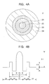
- FIG. 2A is a sectional view of an SMF (1) having a positive dispersion and a positive dispersion slope in the 1.5 ⁇ m band.
- a side core 12 is formed around the outer circumference of the center core 11 and a cladding 13 is formed around the outer circumference of the side core.
- FIG. 2B is the refractive index profile corresponding to the above parts.
- the center core 11 has a relative refractive index difference ⁇ 1 with respect to the cladding 13, while the side core 12 has a relative refractive index difference ⁇ 2 with respect to the cladding.
- the distribution of refractive indexes forms a so-called step-like shape.
- the relative refractive index difference ⁇ 1 is 0.40%, while the relative refractive index difference ⁇ 2 is 0.20%.
- the parameter ⁇ in approximation by the following formula (4) of the refractive index profile (n(r)) of the center core and the distance r from the center of the optical fiber is about 4: n ( r ) ⁇ 1-2 ⁇ ( r a ) ⁇ ⁇ where, a is the center core radius and
- ⁇ is (n 1 -n 2 )/n 1 (n 1 is the maximum refractive index of the center core, while n 2 is the refractive index of the cladding).
- the ratio Ra of the diameter 2a of the center core 11 with respect to the diameter 2b of the side core 12 is for example 0.45 or so.
- the effective core area (A eff ) of the SMF is for example at least 70 ⁇ m 2 , preferably at least 90 ⁇ m 2 .
- the ⁇ 1, ⁇ 2, ⁇ , 2a, 2b, A eff , and other parameters can be suitably adjusted so that the dispersion in the 1.55 ⁇ m band becomes 8 to 15 ps/nm/km and the dispersion slope becomes at least 0.04 ps/nm 2 /km (for example, 0.06 to 0.07 ps/nm 2 /km).
- RDF dispersion compensation fiber
- the RDF (negative fiber) in this embodiment it is possible to use a fiber optimized based on a fiber using a side core layer having the effect of suppressing enlargement of dispersion and increase of bending loss, that is, a W-shape, plus one additional side core so as to keep the bending loss at a diameter of 20 mm not more than 5 dB/m.
- FIG. 3 shows the changes in the transmission loss characteristic when changing the profile of a conventional RDF to change the bending loss.
- RDF negative fiber
- FIG. 4A is a sectional view of a line use dispersion compensation fiber RDF (2) having a negative dispersion and a negative dispersion slope in the 1.5 ⁇ m band. This is structured as a W-type plus the addition of one side core.
- a first side core 22 and second side core 23 are formed around the outer circumference of the center core 21 and a cladding 24 is formed around the outer circumference of the side cores.
- FIG. 4B is a refractive index profile corresponding to the above parts.
- the center core 21 has a relative refractive index ⁇ 1 with respect to the cladding 24, while the first side core 22 and the second side core 33 have relative refractive indexes ⁇ 2 and ⁇ 3 with respect to the cladding 24.
- the parameter ⁇ for the approximation by the above formula (4) of the refractive index profile (n(r)) of the center core and the distance r from the center of the optical fiber, the diameter 2a of the center core 21, the diameter 2b of the first side core 22, the diameter 2c of the second side core 23, and the effective core area (A eff ) are set as follows:
- the ⁇ 1 is set to 1.2% to 1.5%.
- a small ⁇ 1 is effective not only for reducing the transmission loss, but also improving the PMD characteristic and non-linear characteristic.
- the values of ⁇ , ⁇ 2, ⁇ 3, and a:b:c are adjusted so that the dispersion per slope (DPS) in the 1.55 ⁇ m band becomes not more than 300 nm and the A eff becomes a value larger than that of a conventional DCF, that is, at least 20 ⁇ m 2 .
- ⁇ is preferably made 2 to 5. If less than 2, the bending loss increases, while if more than 5, the compensation rate ends up becoming worse.
- ⁇ 2 is preferably made -0.50 to -0.35%. If less than -0.50%, the bending loss increases, while if more than -0.35%, the compensation rate ends up becoming worse.
- ⁇ 3 is preferably made 0.15 to 0.30%. If less than 0.15%, the bending loss increases, while if more than 0.30%, the DPS also becomes a large one of at least 300 nm and the cutoff wavelength also ends up increasing.
- a:b:c be made 1:1.7 to 2.0:2.4 to 3.0.
- a 1, if b is less than 1.7, the compensation rate falls, while if more than 2.0, bending loss occurs.
- a 1, if c is less than 2.4, the bending loss increases, while if more than 3.0, the cutoff wavelength and DPS increase.
- an RDF negative fiber having a dispersion of not more than -40 ps/nm/km, a DPS of not more than 300 nm, an A eff of not less than 20 ⁇ m 2 , and a bending loss of not more than 5 dB/m.
- the transmission loss is preferably not more than 0.50 dB/km, more preferably not more than 0.27 dB/km.
- dispersion management optical transmission system of the present embodiment it is possible to achieve low non-linearity (suppress FWM or SPM, XPM, etc.), dispersion flatness, and low bending loss characteristics at the same time as low loss characteristics.
- the characteristics of the dispersion management optical transmission system of the present embodiment of low loss characteristics, low non-linearity, low bending loss, and low dispersion slope are optimal for a WDM transmission line.
- a dispersion management optical transmission system of the present embodiment it is possible to easily prepare an optical transmission system suitable for high speed, large capacity transmission.
- the values of the ⁇ , Ra, etc. however were finely adjusted for each fiber so as not to cause deterioration of the bending loss.
- the core diameters, loss, dispersion, dispersion slope, dispersion per slope (DPS), mode field diameter (MFD), effective core area (A eff ), cutoff wavelength ( ⁇ c), bending loss at a diameter of 20 mm (20 ⁇ bending), and polarized mode dispersion (PMD) of the positive fibers are shown in Table 1.
- the positive fibers of Sample Nos. 1 to 4 all had transmission losses of not more than 0.20 dB/km or all good values.
- the positive fibers of Sample Nos. 1 to 3 had A eff values larger than that of a conventional SMF, that is, at least 90 ⁇ m 2 . Further, the positive fiber of Sample No. 4 also had one of over 70 ⁇ m 2 or an enlarged A eff value.
- negative fibers having the W-type structure shown in FIG. 4 plus a further side core layer were prepared as Sample Nos. 1 and 2.
- the core diameters, ⁇ 1, loss, dispersion, dispersion slope, dispersion per slope (DPS), effective core area (A eff ), cutoff wavelength ( ⁇ c), bending loss at a diameter of 20 mm (20 ⁇ bending), and polarization mode dispersion (PMD) of the negative fibers are shown in Table 2.
- a low loss characteristic is obtained by keeping the bending loss of the negative fiber to a small value.
- the DPS is also a small one of not more than 300 nm, so dispersion flatness of the line as a whole can also be expected.
- the length of the positive fiber can be set to at least four times the length of the negative fiber of the present embodiment.
- the A eff is also at least 20 ⁇ m 2 or a large value compared with a conventional DCF.
- the numbers of the positive fibers and negative fibers correspond to the sample numbers shown in Table 1 and Table 2.
- "Pos.1+Neg.1” is an optical transmission system combining a positive fiber of Sample No. 1 in Table 1 and a negative fiber of Sample No. 2 in Table 2.
- the dispersion slope was suppressed to not more than 0.030 ps/nm 2 /km. The smallest one was about 0.010 ps/nm 2 /km.
- the transmission loss was kept to a low level of not more than 0.21 dB/km, while the PMD was a low value of not more than 0.1 ps/ ⁇ km in all fibers no matter what the combination.
- the SMF (positive fiber) and RDF (negative fiber) may have structures other than those explained in the embodiment.
- a dispersion management optical transmission system obtained by connecting an optical fiber having a positive dispersion and a positive dispersion slope in the 1.5 ⁇ m band and an optical fiber having a negative dispersion and a negative dispersion slope in the 1.5 ⁇ m band so as to suppress dispersion in the 1.5 ⁇ m band, wherein the occurrence of non-linear phenomena is suppressed and the transmission loss is reduced, and an optical transmission line using the same.
- this dispersion management optical transmission system or an optical transmission line using the same for transmission on the sea floor or on the ground it is possible to transmit signals stably at a higher speed in a larger capacity.
Landscapes
- Chemical & Material Sciences (AREA)
- Dispersion Chemistry (AREA)
- Physics & Mathematics (AREA)
- General Physics & Mathematics (AREA)
- Optics & Photonics (AREA)
- Optical Communication System (AREA)
Applications Claiming Priority (4)
| Application Number | Priority Date | Filing Date | Title |
|---|---|---|---|
| JP2001115943 | 2001-04-13 | ||
| JP2001115943 | 2001-04-13 | ||
| JP2002020683 | 2002-01-29 | ||
| JP2002020683 | 2002-01-29 |
Publications (2)
| Publication Number | Publication Date |
|---|---|
| EP1249721A2 true EP1249721A2 (fr) | 2002-10-16 |
| EP1249721A3 EP1249721A3 (fr) | 2004-12-08 |
Family
ID=26613599
Family Applications (1)
| Application Number | Title | Priority Date | Filing Date |
|---|---|---|---|
| EP02252576A Withdrawn EP1249721A3 (fr) | 2001-04-13 | 2002-04-10 | Système de transmission optique à gestion de la dispersion, et ligne de transmission optique |
Country Status (6)
| Country | Link |
|---|---|
| US (1) | US6707971B2 (fr) |
| EP (1) | EP1249721A3 (fr) |
| CN (1) | CN1381740A (fr) |
| AU (1) | AU3431202A (fr) |
| BR (1) | BR0201291A (fr) |
| CA (1) | CA2380342A1 (fr) |
Families Citing this family (3)
| Publication number | Priority date | Publication date | Assignee | Title |
|---|---|---|---|---|
| US6865328B2 (en) * | 2002-10-11 | 2005-03-08 | Corning Incorporated | Positive dispersion optical fiber |
| JP5619516B2 (ja) | 2010-08-04 | 2014-11-05 | 古河電気工業株式会社 | 光ファイバ |
| WO2016108848A1 (fr) * | 2014-12-30 | 2016-07-07 | Halliburton Energy Services, Inc. | Correction de dispersion chromatique dans une détection distribuée à distance |
Citations (4)
| Publication number | Priority date | Publication date | Assignee | Title |
|---|---|---|---|---|
| JPH09211511A (ja) * | 1996-02-05 | 1997-08-15 | Furukawa Electric Co Ltd:The | 光通信システム |
| WO1999042869A1 (fr) * | 1998-02-23 | 1999-08-26 | Corning Incorporated | Guide d'onde gere en dispersion faible pente |
| WO2001001179A1 (fr) * | 1999-06-28 | 2001-01-04 | The Furukawa Electric Co., Ltd. | Ligne de transmission optique |
| WO2001014917A1 (fr) * | 1999-08-20 | 2001-03-01 | The Furukawa Electric Co., Ltd. | Fibre optique et ligne de transmission optique comprenant cette derniere |
Family Cites Families (5)
| Publication number | Priority date | Publication date | Assignee | Title |
|---|---|---|---|---|
| US221569A (en) * | 1879-11-11 | Improvement in apparatus for taking casts of the human form | ||
| JP3298316B2 (ja) | 1994-07-28 | 2002-07-02 | 松下電工株式会社 | 外壁材、その施工方法およびその目地構造 |
| US6421490B1 (en) * | 1998-02-23 | 2002-07-16 | Corning Incorporated | Low slope dispersion managed waveguide |
| JP4586268B2 (ja) * | 2000-12-25 | 2010-11-24 | ヤマハ株式会社 | ネットワークにおけるデータ送受信管理方法及び同データ送受信管理装置 |
| CN100518191C (zh) * | 2006-03-21 | 2009-07-22 | 华为技术有限公司 | 通讯网络中对服务质量进行保障的方法及系统 |
-
2002
- 2002-04-03 CA CA002380342A patent/CA2380342A1/fr not_active Abandoned
- 2002-04-08 US US10/117,170 patent/US6707971B2/en not_active Expired - Lifetime
- 2002-04-10 EP EP02252576A patent/EP1249721A3/fr not_active Withdrawn
- 2002-04-11 CN CN02105880A patent/CN1381740A/zh active Pending
- 2002-04-12 AU AU34312/02A patent/AU3431202A/en not_active Abandoned
- 2002-04-15 BR BR0201291-0A patent/BR0201291A/pt not_active Application Discontinuation
Patent Citations (4)
| Publication number | Priority date | Publication date | Assignee | Title |
|---|---|---|---|---|
| JPH09211511A (ja) * | 1996-02-05 | 1997-08-15 | Furukawa Electric Co Ltd:The | 光通信システム |
| WO1999042869A1 (fr) * | 1998-02-23 | 1999-08-26 | Corning Incorporated | Guide d'onde gere en dispersion faible pente |
| WO2001001179A1 (fr) * | 1999-06-28 | 2001-01-04 | The Furukawa Electric Co., Ltd. | Ligne de transmission optique |
| WO2001014917A1 (fr) * | 1999-08-20 | 2001-03-01 | The Furukawa Electric Co., Ltd. | Fibre optique et ligne de transmission optique comprenant cette derniere |
Non-Patent Citations (1)
| Title |
|---|
| PATENT ABSTRACTS OF JAPAN vol. 1997, no. 12, 25 December 1997 (1997-12-25) & JP 9 211511 A (FURUKAWA ELECTRIC CO LTD:THE), 15 August 1997 (1997-08-15) * |
Also Published As
| Publication number | Publication date |
|---|---|
| BR0201291A (pt) | 2003-03-11 |
| EP1249721A3 (fr) | 2004-12-08 |
| CN1381740A (zh) | 2002-11-27 |
| AU3431202A (en) | 2002-10-17 |
| CA2380342A1 (fr) | 2002-10-13 |
| US6707971B2 (en) | 2004-03-16 |
| US20030007737A1 (en) | 2003-01-09 |
Similar Documents
| Publication | Publication Date | Title |
|---|---|---|
| US6600862B2 (en) | Optical fiber and optical transmission line | |
| EP1241495A2 (fr) | Fibre optique et ligne de transmission à multiplexage de longueur d'onde | |
| US6591048B2 (en) | Dispersion compensating optical fiber and optical transmission line using the optical fiber | |
| JP4531954B2 (ja) | 光ファイバおよびその光ファイバを用いた光伝送路 | |
| EP1211533A2 (fr) | Fibre optique et système de communication optique l'utilisant | |
| EP1245972A2 (fr) | Fibre optique, ligne de transmission optique utilisant cette fibre optique, et système de transmission optique | |
| US7327921B2 (en) | Chromatic dispersion compensating optical fibre | |
| US20060233503A1 (en) | Optical fiber and optical communication system employing the optical fiber | |
| US6587627B2 (en) | Dispersion-compensating fiber, and dispersion-compensating module and hybrid optical fiber link using the same | |
| US6983094B2 (en) | Optical fiber and optical transmission system using such optical fiber | |
| US6701051B2 (en) | Optical fiber transmission line | |
| US6707971B2 (en) | Dispersion management optical transmission system and optical transmission line | |
| US6879762B2 (en) | Optical transmission line and optical transmission system using optical transmission line | |
| EP1288684A2 (fr) | Fibre optique a dispersion negative et ligne de transmission optique utilisant ladite fibre | |
| JP3479272B2 (ja) | 分散シフト光ファイバ及び光通信システム | |
| JP2003298520A (ja) | 分散マネージメント光伝送システムおよび光伝送路 | |
| JP4205455B2 (ja) | 光ファイバ及びそれを用いた光伝送システム | |
| JP2003172843A (ja) | 光ファイバおよびその光ファイバを用いた光ファイバモジュールならびに光増幅器 | |
| JP2001074964A (ja) | 光ファイバおよびそれを用いた光伝送路 | |
| JP2004093650A (ja) | 光伝送路およびそれに用いる分散補償光ファイバ | |
| JP2004077663A (ja) | 光ファイバ、それを用いた光伝送システム |
Legal Events
| Date | Code | Title | Description |
|---|---|---|---|
| PUAI | Public reference made under article 153(3) epc to a published international application that has entered the european phase |
Free format text: ORIGINAL CODE: 0009012 |
|
| AK | Designated contracting states |
Kind code of ref document: A2 Designated state(s): AT BE CH CY DE DK ES FI FR GB GR IE IT LI LU MC NL PT SE TR |
|
| AX | Request for extension of the european patent |
Free format text: AL;LT;LV;MK;RO;SI |
|
| PUAL | Search report despatched |
Free format text: ORIGINAL CODE: 0009013 |
|
| AK | Designated contracting states |
Kind code of ref document: A3 Designated state(s): AT BE CH CY DE DK ES FI FR GB GR IE IT LI LU MC NL PT SE TR |
|
| AX | Request for extension of the european patent |
Extension state: AL LT LV MK RO SI |
|
| RIC1 | Information provided on ipc code assigned before grant |
Ipc: 7G 02B 6/16 B Ipc: 7G 02B 6/293 A |
|
| AKX | Designation fees paid |
Designated state(s): DE DK FR GB IT |
|
| STAA | Information on the status of an ep patent application or granted ep patent |
Free format text: STATUS: THE APPLICATION IS DEEMED TO BE WITHDRAWN |
|
| 18D | Application deemed to be withdrawn |
Effective date: 20050701 |