EP1249611A2 - Pumpe mit Strömungsventil - Google Patents
Pumpe mit Strömungsventil Download PDFInfo
- Publication number
- EP1249611A2 EP1249611A2 EP02007912A EP02007912A EP1249611A2 EP 1249611 A2 EP1249611 A2 EP 1249611A2 EP 02007912 A EP02007912 A EP 02007912A EP 02007912 A EP02007912 A EP 02007912A EP 1249611 A2 EP1249611 A2 EP 1249611A2
- Authority
- EP
- European Patent Office
- Prior art keywords
- flange
- valve
- switch assembly
- pad
- housing
- Prior art date
- Legal status (The legal status is an assumption and is not a legal conclusion. Google has not performed a legal analysis and makes no representation as to the accuracy of the status listed.)
- Granted
Links
Images





Classifications
-
- F—MECHANICAL ENGINEERING; LIGHTING; HEATING; WEAPONS; BLASTING
- F04—POSITIVE - DISPLACEMENT MACHINES FOR LIQUIDS; PUMPS FOR LIQUIDS OR ELASTIC FLUIDS
- F04B—POSITIVE-DISPLACEMENT MACHINES FOR LIQUIDS; PUMPS
- F04B49/00—Control, e.g. of pump delivery, or pump pressure of, or safety measures for, machines, pumps, or pumping installations, not otherwise provided for, or of interest apart from, groups F04B1/00 - F04B47/00
- F04B49/02—Stopping, starting, unloading or idling control
-
- F—MECHANICAL ENGINEERING; LIGHTING; HEATING; WEAPONS; BLASTING
- F04—POSITIVE - DISPLACEMENT MACHINES FOR LIQUIDS; PUMPS FOR LIQUIDS OR ELASTIC FLUIDS
- F04D—NON-POSITIVE-DISPLACEMENT PUMPS
- F04D15/00—Control, e.g. regulation, of pumps, pumping installations or systems
- F04D15/02—Stopping of pumps, or operating valves, on occurrence of unwanted conditions
-
- F—MECHANICAL ENGINEERING; LIGHTING; HEATING; WEAPONS; BLASTING
- F04—POSITIVE - DISPLACEMENT MACHINES FOR LIQUIDS; PUMPS FOR LIQUIDS OR ELASTIC FLUIDS
- F04D—NON-POSITIVE-DISPLACEMENT PUMPS
- F04D13/00—Pumping installations or systems
- F04D13/02—Units comprising pumps and their driving means
- F04D13/06—Units comprising pumps and their driving means the pump being electrically driven
Definitions
- the present invention relates to an automatic Pump, especially an automatic pump that doesn't can only be installed regardless of direction, but also made in a simple and easy way can be, reducing the manufacturing cost of automatic pump can be reduced.
- a pump is an apparatus for transporting fluid by operating an engine. Especially with one automatic pump, the flow of the fluid becomes automatic controlled.
- a conventional one automatic pump described. 1 is a partial section of a side view of a conventional automatic pump, the schematic of their construction shows.
- the pump housing 11 comprises a pump a housing 11 in which a fluid channel is formed.
- the Fluid channel in the pump housing 11 is with an inlet pipe 13a and an outlet pipe 13b, through which Fluid is sucked in or expelled.
- the pump housing 11 contains an impeller 17.
- the impeller 17 is rotated by a motor 15 and causes the suction of the Fluids through the inlet pipe 13a and the ejection of the Fluids through the outlet pipe 13b.
- valve assembly 20 Next are at one end of the fluid channel of the pump housing 11 on the outlet pipe 13b side, a valve assembly 20 and a switch assembly 30 arranged.
- the Valve assembly 20 and the switch assembly 30 that Inlet pipe 13a with the outlet pipe 13b and control the Motor 15.
- the switch assembly 30 is with a lead wire 39 connected to the control unit 40, and the Valve assembly 20 is under switch assembly 30 arranged.
- the valve assembly 20 includes a valve 21, a guide rod 25 for guiding a vertical Movement of the valve 21 and a magnet 23, which is arranged on an upper side of the valve 21.
- connection opening 19 As shown by the solid line in Fig. 1. From this state, after opening a Hahns (or a valve) on the consumer side that Fluid in outlet tube 13b is drained through the tap while valve 21 at the same time due to the hydraulic pressure difference between the inlet pipe 13a and the outlet pipe 13b along the guide rod 25 moved up. Thereupon the connection opening 19 opened as shown by the broken line in Fig. 1, and the switch assembly 30 is shown by the magnet 23 arranged on the valve 21 is switched on and sends an operating signal to the control unit 40. The control unit 40 then actuates the motor 15, which rotates the impeller 17 and thereby the fluid sucks and ejects.
- FIGS. 1 to 4 Switch assembly 30 described.
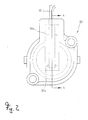
- Figure 2 is a top view on the switch assembly of FIGS. 1, 3 a section along the line A-A in Fig. 2, and
- Fig. 4th is a perspective view of the reed switch from Fig. 3.
- the switch assembly includes 30 a reed switch 31 and brass plates 33.
- the brass plates 33 are provided with lower holes 33a, in which the ends of the reed switch 31 are inserted and upper holes 33b, in which the electrical wires 39 are used. Both ends of the reed switch 31 and the electric wires 39 into the lower holes 33a and the upper holes 33b used and soldered in this.
- the brass plates 33 on which the reed switch 31 and the electrical Wires 39 are attached to the space 35a used in a switch assembly body 35 is formed, as shown in Fig. 3.
- the brass plates 33 shown in 35a are attached that the reed switch 31 in lateral Directions moved, and the switch assembly cover 37, which rests on the brass plates 33, prevents that the reed switch 31 in vertical Directions moved.
- the reed switch is also small due to its small size not easy and convenient to use and with the lower ones Solder holes in the brass plates.
- the present invention aims to do so ab, the aforementioned problems with the state of the Technology are connected, to solve, and a task of The present invention is an automatic pump the one valve assembly releasably with a pump housing can be connected and an angular position of the valve assembly can be set so that the automatic Pump can be installed regardless of the direction can.
- Another object of the present invention is automatic pump with a switch assembly be made in a simple and easy way can, reducing the manufacturing cost of automatic Pump can be reduced.
- a pump housing in which a Fluid channel is formed, comprising the pump housing Inlet pipe and an outlet pipe connected to the fluid channel are connected; an impeller arranged in the housing, sucked through the fluid into the inlet pipe and through the outlet pipe is ejected; one on one side of the housing arranged motor that the impeller rotates; a valve assembly comprising a valve housing, a valve and a magnet, the valve housing at a first end with the outlet pipe and at a second end connected to a consumer side and the valve in the valve housing is vertically movable Is arranged and distinguished by its own Weight down and due to hydraulic pressure difference moves up while there is an interior of the valve housing opens or closes, and wherein the magnet is placed on top of the valve is; a switch assembly that is on a top of the valve housing is arranged and by the upward and downward movement of the arranged on the valve Magnet is turned on and off; one on one Control unit arranged on the side of the pump Signal from the switch assembly to control the motor obtained
- the means mentioned preferably comprise: a first flange, which is in one part with the outer periphery of the outlet tube is shaped and at least has two first mounting holes through circumferential sections through the first flange, the first mounting holes being point symmetrical with respect arranged on a center point of the first flange are; a second flange that is in one part with the valve body is molded and two second mounting holes has by circumferential sections of the second Flange are formed therethrough, the second mounting holes point symmetrical with respect to a center the second flange are arranged; and assembly links, through the first mounting holes and the second mounting holes are screwed to the first To connect the flange and the second flange together being the angular position in which the second Flange is connected to the first flange by Rotation of the second flange in a predetermined Angular interval can be selected.
- the switch assembly also includes: one Switch assembly body attached to an upper section the valve housing is attached, the Switch assembly body on a middle section an inside of the switch assembly body with a Fixing groove is provided; a document that has a shape that corresponds to the shape of the fixing groove, and inserted into the fixation groove so that it sits in it, with the pad on is provided at both ends with conductive patterns and on one middle side section is formed with an empty space is; a reed switch with a medium one Section is arranged in the empty space of the pad and both ends with the conductor patterns of the pad are soldered; a lead wire, the first of which The end is soldered to the conductor diagrams and its second end is connected to the control unit; and one Switch assembly cover, on an upper section the switch assembly body is attached, the switch assembly cover a variety of opposite to the fixing groove arranged fixing Has protrusions that press and hold the pad.
- FIG. 5 shows a partially exploded view executed perspective view of an automatic Pump according to a preferred embodiment of the present invention.
- an automatic pump 100 includes in the present embodiment, a pump housing 110, an impeller 120, a motor 130, a control unit 140, a valve assembly 150 and a switch assembly 160th
- a fluid channel is formed in the pump housing 110, and an inlet pipe 111 and an outlet pipe 113 are on the one or the other side of the pump housing 110 arranged and connected to the fluid channel.
- the impeller 120 is arranged in the pump housing 110 and causes that fluid into the inlet tube 111 through the fluid channel and out of the outlet pipe 113 flows.
- Motor 130 is on one side of the pump housing 110 and is arranged by the control unit 140 controlled that it rotates and stops the impeller 120.
- the control unit 140 actuates and stops the motor 130 in accordance with signals from the switch assembly 160 caused by the up and down movement of the Valve assembly 150 is turned on and off.
- the automatic pump according to the present embodiment includes means for adjusting an installation position the valve assembly 150, whereby the valve assembly 150 can be held in an upright position while it is possible to have the valve assembly 150 on the outlet pipe 113 to be assembled and disassembled from the outlet pipe 113, what follows with reference to FIG. 5 and Fig. 6 is described.
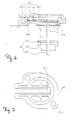
- Fig. 6 shows a section along line B-B in Fig. 5, which is a construction a switch assembly 160 shows how in an automatic Pump 100 in the present embodiment is used.
- the Valve assembly 150 includes a valve housing 151, which is connected at one end to the outlet pipe 113 and connected to a consumer side at the other end is.
- the valve housing 151 contains a valve 153, and on top of valve 153 is a magnet arranged.
- a guide rod 157 on one Underside of the switch assembly 160 attached and extended through the valve 153 so that the valve 153 along the guide rod 157 upwards and is led down.
- An interior of the valve housing 151 is due to the up and down movements of valve 153 opened and closed.
- the aforementioned means comprise a first flange 171, a second flange 175 and mounting members 179 for fastening the first flange 171 to the second Flange 175.
- the first flange 171 is in one part with the outer
- the circumference of the outlet pipe 113 is shaped
- the second Flange 175 is integral with the valve body 151 shaped.
- First mounting holes 171a pass through Peripheral portions of the first flange 171
- second Mounting holes 175a pass through peripheral portions of the second flange 175.
- the first Mounting holes 171a and the second mounting holes 175a each point symmetrical with respect to centers the first flange 171 and the second flange 175 arranged.
- assembly members 179 such as e.g. Screws through the first mounting holes 171a and screwed the second mounting holes 175a to the first Flange 171 and the second flange 175 with each other connect to.
- the mounting members 179 are released the first flange 171 becomes the second flange 175 dismantled.
- first mounting holes 171a of the first Flange 171 which is circumferential at an angular interval are spaced from each other by 90 °. Since the first mounting holes in the circumferential direction at an angular interval are spaced from each other by 90 ° Angular positions in which the second flange 175 with the first flange 171 is selected, if the second flange 175 at an angular interval is rotated by 90 °. If the number of first mounting holes 171a is greater than four, the angular positions, in which the second flange 175 mates with the first Flange 171 is connected to be chosen during the second flange at an angular interval of less than Is turned 90 °.
- the angular position of the second flange 175 with respect to the first flange 171, in which the valve assembly 150 with the pump housing 110 can be connected in an upright position can be set more precisely.
- the number of the second Mounting holes 175a an even number like two, four, is six and eight. It is most preferable if the number of the second mounting holes 175a is two, the dimensions of the second flange 175 to a minimum to restrict. For a more detailed explanation: If the number of second mounting holes 175a at least is four, the distances between the second Mounting holes 175a are increased to prevent that 180 disturbs the surrounding components after 180 through the first mounting holes 171a and the second Mounting holes 175a was screwed to the first one To connect flange 171 to the second flange 175. To the distances between the second mounting holes 175a, the size of the second flange 175 be increased so that the volume of automatic Pump is increased.
- Fig. 7 shows one Top view of a switch assembly body as in the switch assembly shown in Fig. 6 used becomes. 8 shows a view from below of one Switch assembly cover, as shown in Fig. 6 Switch assembly is used, and Fig. 9 shows a perspective view of the assembled Reed switch and the pad used for the in Fig. 6 switch assembly shown can be used.
- the switch assembly 160 includes a switch assembly body 161, a switch assembly cover 163, one Pad 165, a reed switch 167 and a lead wire 169. As shown, is in a medium Section of an inner surface of the switch assembly body 161 a fixing groove 161a with a rectangular one Shaped, and first screw holes 161b into which Screws 181 (see Fig. 5) are screwed in formed on an edge of the switch assembly body 161.
- the switch assembly body 161 is with the Switch assembly cover 163 assembled.
- the switch assembly cover 163 has a variety of fixatives Protrusions 163a formed on an inner surface of the Switch assembly cover 163 are shaped and opposite the fixing groove 161a of the switch assembly body 161 are arranged.
- the fixing projections 163a of the switch assembly cover 163 fix the base 165.
- the position of the fixative Projections 163a chosen so that the fixing Projections 163 the circuit patterns 165a, the reed switch 167 and the lead wire 169, which on the pad 165 are arranged, do not disturb.
- Second screw holes 163b, the first screw holes 161b of the Switch assembly body 161 correspond, run through an edge of the switch assembly cover 163. Die Screws 181 (see Fig.
- the pad 165 has one Shape corresponding to the shape of the fixing groove 161a, and the conductive patterns 165a are at both ends of the pad 165 formed while a void 165b on a middle position of the pad 165 is provided is. Furthermore, one end of the lead wire 169 is on one of the conductive patterns 165a soldered, and the other End of lead wire 169 is with controller 140 connected.
- the pad 165 on which the reed switch 167 and the lead wire 169 are attached in the fixing groove 161a is inserted so that it is in it sitting. If the switch assembly cover 163 with the Switch assembly body 161 is assembled the fixing projections 163a of the switch assembly cover 163 in contact with the surface document 165.
- the pad 165 Since the pad 165 is seated in the fixing groove 161a, can the reed switch connected to the pad 165 167 do not move in lateral directions. And as the pad 165 from the fixing protrusions 163a is pressed and held, the pad can 165 do not move in vertical directions. To the To fix the pad 165 more firmly in the fixing groove 161a, can an adhesive on the pad 165 and the fixing groove 161a are applied.
- FIG. 10 shows a perspective view of an automatic Pump according to an embodiment of the present Invention in which a valve assembly in a upright position.
- second flange 175, which is attached to the valve housing 151 is connected to the first flange 171 on the outlet pipe 113 is attached.
- the pump housing 110 has a variety of flat ones Projections 118 (see Figures 5 and 10). If the pump housing 110 faces down, the flat ones are Protrusions 118 in contact with the ground and wear the pump housing 110.
- valve 153 closes by its own Weight has moved down, as by the solid line in Fig. 6, the interior of the valve housing 151. From this state on after opening a tap (or valve) the consumer in the fluid in the valve housing 151, connected to the consumer side through which Tap drained while turning the valve 153 due to a difference between the pressure in the Inlet pipe 111 and the pressure in the valve housing 151 next to the consumer side along the guide rod 157 moved up. As in the broken line in Fig. 6, thereupon the interior of the valve housing 151 opened while the Reed switch 167 through the one on the top of the valve 153 arranged magnet 155 is turned on and sends an operating signal to the control unit 140. The control unit 140 then actuates the motor 130, which rotates the impeller 120 and thereby draws in the fluid and ejects.
- the inventive automatic pump not just the valve assembly releasably connected to the pump housing, but there may also be an angular position of the valve assembly can be set so that the automatic pump is independent of the direction can be installed.
- the reed switch is attached to the pad by connecting both ends of the reed switch with the Conductor patterns are welded to the base, after a middle section of the reed switch in the empty space was arranged in a middle Section of the pad is formed. So that's it manual work of attaching the reed switch the pad simple and easy.
Landscapes
- Engineering & Computer Science (AREA)
- Mechanical Engineering (AREA)
- General Engineering & Computer Science (AREA)
- Structures Of Non-Positive Displacement Pumps (AREA)
- Details Of Reciprocating Pumps (AREA)
- Check Valves (AREA)
Abstract
Description
Claims (3)
- Automatische Pumpe umfassend:ein Pumpengehäuse, in dem ein Fluidkanal geformt ist, das Pumpengehäuse umfassend ein Einlaßrohr undein Auslaßrohr, die mit dem Fluidkanal verbunden sind;ein im Gehäuse angeordnetes Flügelrad, durch das Fluid in das Einlaßrohr angesaugt und durch das Auslaßrohr ausgestoßen wird;einen an einer Seite des Gehäuses angeordneten Motor, der das Flügelrad dreht;eine Ventilbaugruppe umfassend ein Ventilgehäuse, ein Ventil und einen Magneten, wobei das Ventilgehäuse an einem ersten Ende mit dem Auslaßrohr und an einem zweiten Ende mit einer Verbraucherseite verbunden ist und das Ventil im Ventilgehäuse auf vertikal bewegliche Weise angeordnet ist und sich durch sein eigenes Gewicht nach unten und durch Hydraulikdruckunterschied nach oben bewegt, während es gleichzeitig einen Innenraum des Ventilgehäuses öffnet bzw. schließt, und wobei der Magnet auf einer Oberseite des Ventils angeordnet ist;eine Schalterbaugruppe, die auf einer Oberseite des Ventilgehäuses angeordnet ist und durch die Aufwärts- und Abwärtsbewegung des auf dem Ventil angeordneten Magneten ein- und ausgeschaltet wird; ein auf einer Seite der Pumpe angeordnetes Steuerwerk, das ein Signal von der Schalterbaugruppe zum Ansteuern des Motors erhält; undMittel zum Einstellen einer Einbauposition der Ventilbaugruppe, so daß die Ventilbaugruppe aufrecht gehalten wird, wobei die genannten Mittel es möglich machen, daß die Ventilbaugruppe an dem Auslaßrohr befestigt und vom Auslaßrohr abmontiert werden kann.
- Automatische Pumpe gemäß Anspruch 1, dadurch gekennzeichnet, daß die genannten Mittel umfassen:einen ersten Flansch, der in einem Teil mit dem äußeren Umfang des Auslaßrohrs geformt ist und mindestens zwei erste Montagelöcher hat, die durch Umfangsabschnitte des ersten Flanschs hindurch geformt sind, wobei die ersten Montagelöcher punktsymmetrisch in Bezug auf einen Mittelpunkt des ersten Flanschs angeordnet sind;einen zweiten Flansch, der in einem Teil mit dem Ventilgehäuse geformt ist und zwei zweite Montagelöcher hat, die durch Umfangsabschnitte des zweiten Flanschs hindurch geformt sind, wobei die zweiten Montagelöcher punktsymmetrisch in Bezug auf einen Mittelpunkt des zweiten Flanschs angeordnet sind; undmit dem ersten Flansch montierteMontageglieder, die durch die ersten Montagelöcher und die zweiten Montagelöcher geschraubt werden, um den ersten Flansch und den zweiten Flansch miteinander zu verbinden,wobei die Winkelposition, in der der zweite Flansch mit dem ersten Flansch verbunden wird, durch Drehung des zweiten Flanschs in einem vorbestimmten Winkelintervall gewählt werden kann.
- Automatische Pumpe nach Anspruch 1, dadurch gekennzeichnet, daß die Schalterbaugruppe umfaßt:einen Schalterbaugruppenkörper, der an einem oberen Abschnitt des Ventilgehäuses befestigt wird, wobei der Schalterbaugruppenkörper an einem mittleren Abschnitt einer Innenseite des Schalterbaugruppenkörpers mit einer Fixierungsrille versehen ist;eine Unterlage, die eine Form hat, welche der Form der Fixierungsrille entspricht, und die in die Fixierungsrille eingesetzt wird, so daß sie darin sitzt, wobei die Unterlage an beiden Enden mit Leiterbildern versehen ist und an einem mittleren Seitenabschnitt mit einem Leerraum ausgebildet ist;einen Reed-Schalter, der mit einem mittleren Abschnitt im Leerraum der Unterlage angeordnet ist und dessen beide Enden mit den Leiterbildern der Unterlage verlötet sind;einen Leitungsdraht, dessen erstes Ende mit den Leiterbildern verlötet ist und dessen zweites Ende mit dem Steuerwerk verbunden ist; undeinen Schalterbaugruppendeckel, der an einem oberen Abschnitt des Schalterbaugruppenkörpers befestigt ist, wobei der Schalterbaugruppendeckel eine Vielzahl von gegenüber der Fixierungsrille angeordneten fixierenden Vorsprüngen hat, die die Unterlage drücken und halten.
Applications Claiming Priority (2)
| Application Number | Priority Date | Filing Date | Title |
|---|---|---|---|
| KR1020010019550A KR20010067985A (ko) | 2001-04-12 | 2001-04-12 | 자동 펌프 |
| KR2001019550 | 2001-04-12 |
Publications (3)
| Publication Number | Publication Date |
|---|---|
| EP1249611A2 true EP1249611A2 (de) | 2002-10-16 |
| EP1249611A3 EP1249611A3 (de) | 2004-01-02 |
| EP1249611B1 EP1249611B1 (de) | 2009-06-03 |
Family
ID=19708150
Family Applications (1)
| Application Number | Title | Priority Date | Filing Date |
|---|---|---|---|
| EP02007912A Expired - Lifetime EP1249611B1 (de) | 2001-04-12 | 2002-04-09 | Pumpe mit Strömungsventil |
Country Status (4)
| Country | Link |
|---|---|
| EP (1) | EP1249611B1 (de) |
| KR (2) | KR20010067985A (de) |
| CN (1) | CN2538986Y (de) |
| DE (1) | DE50213582D1 (de) |
Families Citing this family (4)
| Publication number | Priority date | Publication date | Assignee | Title |
|---|---|---|---|---|
| KR100764855B1 (ko) * | 2006-05-18 | 2007-10-09 | 윌로펌프 주식회사 | 자동펌프 |
| EP2174007A4 (de) * | 2007-07-02 | 2017-05-10 | Borgwarner Inc. | Einlassentwurf für eine pumpenbaugruppe |
| CN104405628A (zh) * | 2014-12-09 | 2015-03-11 | 合肥新沪屏蔽泵有限公司 | 浮力感应式流量开关 |
| CN110886725B (zh) * | 2019-12-27 | 2020-10-13 | 江苏盐邦泵业制造有限公司 | 一种可变流量式水泵 |
Family Cites Families (6)
| Publication number | Priority date | Publication date | Assignee | Title |
|---|---|---|---|---|
| AT247801B (de) * | 1960-10-10 | 1966-06-27 | Odd Fredheim Johnsen | Druckgesteuertes Ventil, insbesondere für Wasserversorgungssysteme |
| USRE26678E (en) * | 1968-04-18 | 1969-10-07 | Liquid supply system and pump control therefor | |
| GB1360225A (en) * | 1972-10-19 | 1974-07-17 | Distillers Co Carbon Dioxide | Carbonated liquid moving apparatus |
| JPS57148081A (en) * | 1981-03-09 | 1982-09-13 | Sanyo Electric Co Ltd | Automatic operating device for pump |
| JPS58197483A (ja) * | 1982-05-12 | 1983-11-17 | Sanyo Electric Co Ltd | ポンプの自動運転装置 |
| JPS6251774A (ja) * | 1985-08-30 | 1987-03-06 | Mitsubishi Electric Corp | ポンプ装置 |
-
2001
- 2001-04-12 KR KR1020010019550A patent/KR20010067985A/ko active Pending
- 2001-12-12 CN CN01278184U patent/CN2538986Y/zh not_active Expired - Lifetime
-
2002
- 2002-03-26 KR KR10-2002-0016373A patent/KR100437736B1/ko not_active Expired - Lifetime
- 2002-04-09 DE DE50213582T patent/DE50213582D1/de not_active Expired - Lifetime
- 2002-04-09 EP EP02007912A patent/EP1249611B1/de not_active Expired - Lifetime
Also Published As
| Publication number | Publication date |
|---|---|
| KR20020080246A (ko) | 2002-10-23 |
| KR20010067985A (ko) | 2001-07-13 |
| EP1249611B1 (de) | 2009-06-03 |
| DE50213582D1 (de) | 2009-07-16 |
| EP1249611A3 (de) | 2004-01-02 |
| CN2538986Y (zh) | 2003-03-05 |
| KR100437736B1 (ko) | 2004-06-30 |
Similar Documents
| Publication | Publication Date | Title |
|---|---|---|
| EP0271765B1 (de) | Eigenmediumgesteuertes, durch ein vorzugsweise elektromagnetisch betätigtes Steuerventil auslösbares Ventil | |
| DE2933512C2 (de) | Proben-Einspritzventil | |
| EP1985858B1 (de) | Rollenpumpe | |
| DE4037180A1 (de) | Kraftstoffpumpe mit motorischem antrieb | |
| DE202017106212U1 (de) | Ventil | |
| DE2808630C3 (de) | Elektrodenbeheizter Dampferzeuger | |
| WO2000046515A9 (de) | Fluidisches steuerelement | |
| EP0224471B1 (de) | Vorrichtung zum Prüfen von Leiterplatten | |
| EP2225014A1 (de) | Führungseinrichtung für tauchmotorrührwerke | |
| DE102018109792B4 (de) | Adapter zum Anschließen eines Antriebsmittels an einen manuell betätigbaren Absperrhahn und System aus einem solchen Adapter und einem manuell betätigbaren Absperrhahn | |
| DE60203139T2 (de) | Elektrischer Verbinder für Flachkabel und Herstellungsverfahren | |
| EP1193432A2 (de) | Ventil, insbesondere Heizkörperventil | |
| DE3427603C2 (de) | Vorrichtung zum Abschneiden und Biegen von Anschlußdrähten | |
| EP1249611B1 (de) | Pumpe mit Strömungsventil | |
| EP0061041B1 (de) | Vorrichtung zum Betätigen eines heb- und senkbaren Ventilkegels eines Wannenablaufventils | |
| DE102017001651B4 (de) | Signalverbinder | |
| DE3311792C2 (de) | Vorrichtung zum Richten von Anschlußdrähten elektrischer Bauelemente | |
| EP1699967B1 (de) | Elektrische schnittstelle für wasserfürende haushaltsgeräte | |
| DE69616038T2 (de) | Rollenanhebevorrichtung für Haushaltsgeräte | |
| DE202008000539U1 (de) | Mehrwege-Absperrvorrichtung für Flüssigkeiten, insbesondere zur Anwendung an Getränkeautomaten | |
| DE602004006364T2 (de) | Auswechselbares Dreiwegeventil für einen Hausheizungskessel | |
| DE4117647A1 (de) | Hydraulische klemmvorrichtung mit direkt betriebenem klemmelement | |
| DE60130509T2 (de) | Steuerventilbehälter für ein Mehrwegeventil | |
| DE3601018C2 (de) | ||
| CH633403A5 (de) | Vorrichtung zum pruefen und bearbeiten elektromechanischer und elektronischer bauteile. |
Legal Events
| Date | Code | Title | Description |
|---|---|---|---|
| PUAI | Public reference made under article 153(3) epc to a published international application that has entered the european phase |
Free format text: ORIGINAL CODE: 0009012 |
|
| AK | Designated contracting states |
Kind code of ref document: A2 Designated state(s): AT BE CH CY DE DK ES FI FR GB GR IE IT LI LU MC NL PT SE TR |
|
| AX | Request for extension of the european patent |
Free format text: AL;LT;LV;MK;RO;SI |
|
| PUAL | Search report despatched |
Free format text: ORIGINAL CODE: 0009013 |
|
| AK | Designated contracting states |
Kind code of ref document: A3 Designated state(s): AT BE CH CY DE DK ES FI FR GB GR IE IT LI LU MC NL PT SE TR |
|
| AX | Request for extension of the european patent |
Extension state: AL LT LV MK RO SI |
|
| 17P | Request for examination filed |
Effective date: 20040202 |
|
| AKX | Designation fees paid |
Designated state(s): DE FR GB IT |
|
| GRAP | Despatch of communication of intention to grant a patent |
Free format text: ORIGINAL CODE: EPIDOSNIGR1 |
|
| GRAS | Grant fee paid |
Free format text: ORIGINAL CODE: EPIDOSNIGR3 |
|
| RAP1 | Party data changed (applicant data changed or rights of an application transferred) |
Owner name: WILO SE |
|
| GRAA | (expected) grant |
Free format text: ORIGINAL CODE: 0009210 |
|
| AK | Designated contracting states |
Kind code of ref document: B1 Designated state(s): DE FR GB IT |
|
| REG | Reference to a national code |
Ref country code: GB Ref legal event code: FG4D Free format text: NOT ENGLISH |
|
| REF | Corresponds to: |
Ref document number: 50213582 Country of ref document: DE Date of ref document: 20090716 Kind code of ref document: P |
|
| PLBE | No opposition filed within time limit |
Free format text: ORIGINAL CODE: 0009261 |
|
| STAA | Information on the status of an ep patent application or granted ep patent |
Free format text: STATUS: NO OPPOSITION FILED WITHIN TIME LIMIT |
|
| 26N | No opposition filed |
Effective date: 20100304 |
|
| PGFP | Annual fee paid to national office [announced via postgrant information from national office to epo] |
Ref country code: GB Payment date: 20140409 Year of fee payment: 13 |
|
| PGFP | Annual fee paid to national office [announced via postgrant information from national office to epo] |
Ref country code: FR Payment date: 20140409 Year of fee payment: 13 Ref country code: DE Payment date: 20140430 Year of fee payment: 13 Ref country code: IT Payment date: 20140408 Year of fee payment: 13 |
|
| REG | Reference to a national code |
Ref country code: DE Ref legal event code: R119 Ref document number: 50213582 Country of ref document: DE |
|
| GBPC | Gb: european patent ceased through non-payment of renewal fee |
Effective date: 20150409 |
|
| PG25 | Lapsed in a contracting state [announced via postgrant information from national office to epo] |
Ref country code: GB Free format text: LAPSE BECAUSE OF NON-PAYMENT OF DUE FEES Effective date: 20150409 Ref country code: DE Free format text: LAPSE BECAUSE OF NON-PAYMENT OF DUE FEES Effective date: 20151103 Ref country code: IT Free format text: LAPSE BECAUSE OF NON-PAYMENT OF DUE FEES Effective date: 20150409 |
|
| REG | Reference to a national code |
Ref country code: FR Ref legal event code: ST Effective date: 20151231 |
|
| PG25 | Lapsed in a contracting state [announced via postgrant information from national office to epo] |
Ref country code: FR Free format text: LAPSE BECAUSE OF NON-PAYMENT OF DUE FEES Effective date: 20150430 |