EP1249556A2 - Profilblechbahn - Google Patents
Profilblechbahn Download PDFInfo
- Publication number
- EP1249556A2 EP1249556A2 EP02405050A EP02405050A EP1249556A2 EP 1249556 A2 EP1249556 A2 EP 1249556A2 EP 02405050 A EP02405050 A EP 02405050A EP 02405050 A EP02405050 A EP 02405050A EP 1249556 A2 EP1249556 A2 EP 1249556A2
- Authority
- EP
- European Patent Office
- Prior art keywords
- sheet
- web
- profile
- profiled
- fastening flange
- Prior art date
- Legal status (The legal status is an assumption and is not a legal conclusion. Google has not performed a legal analysis and makes no representation as to the accuracy of the status listed.)
- Granted
Links
- 239000002184 metal Substances 0.000 title claims description 51
- 239000011324 bead Substances 0.000 claims abstract description 25
- 230000015572 biosynthetic process Effects 0.000 claims description 38
- 230000004888 barrier function Effects 0.000 claims description 6
- 238000009792 diffusion process Methods 0.000 claims description 2
- 239000012720 thermal barrier coating Substances 0.000 claims 1
- 238000005452 bending Methods 0.000 abstract description 4
- 238000005253 cladding Methods 0.000 abstract 2
- 239000010410 layer Substances 0.000 description 20
- 238000009413 insulation Methods 0.000 description 12
- 125000006850 spacer group Chemical group 0.000 description 10
- 238000012549 training Methods 0.000 description 8
- 238000013461 design Methods 0.000 description 5
- 238000010276 construction Methods 0.000 description 3
- 238000006073 displacement reaction Methods 0.000 description 3
- 238000009423 ventilation Methods 0.000 description 3
- 230000001174 ascending effect Effects 0.000 description 2
- 238000000034 method Methods 0.000 description 2
- 239000002557 mineral fiber Substances 0.000 description 2
- 239000003566 sealing material Substances 0.000 description 2
- 229910001220 stainless steel Inorganic materials 0.000 description 2
- 239000010935 stainless steel Substances 0.000 description 2
- 229910000831 Steel Inorganic materials 0.000 description 1
- 208000027418 Wounds and injury Diseases 0.000 description 1
- 238000010521 absorption reaction Methods 0.000 description 1
- 210000000078 claw Anatomy 0.000 description 1
- 230000006378 damage Effects 0.000 description 1
- 238000011161 development Methods 0.000 description 1
- 230000018109 developmental process Effects 0.000 description 1
- 239000011491 glass wool Substances 0.000 description 1
- 230000006266 hibernation Effects 0.000 description 1
- 230000001771 impaired effect Effects 0.000 description 1
- 208000014674 injury Diseases 0.000 description 1
- 238000003780 insertion Methods 0.000 description 1
- 230000037431 insertion Effects 0.000 description 1
- 238000011900 installation process Methods 0.000 description 1
- 239000011810 insulating material Substances 0.000 description 1
- 239000012528 membrane Substances 0.000 description 1
- 239000011490 mineral wool Substances 0.000 description 1
- 230000000630 rising effect Effects 0.000 description 1
- 238000007789 sealing Methods 0.000 description 1
- 239000002356 single layer Substances 0.000 description 1
- 239000010959 steel Substances 0.000 description 1
- 239000011800 void material Substances 0.000 description 1
Images


Classifications
-
- E—FIXED CONSTRUCTIONS
- E04—BUILDING
- E04D—ROOF COVERINGS; SKY-LIGHTS; GUTTERS; ROOF-WORKING TOOLS
- E04D3/00—Roof covering by making use of flat or curved slabs or stiff sheets
- E04D3/36—Connecting; Fastening
- E04D3/361—Connecting; Fastening by specially-profiled marginal portions of the slabs or sheets
- E04D3/362—Connecting; Fastening by specially-profiled marginal portions of the slabs or sheets by locking the edge of one slab or sheet within the profiled marginal portion of the adjacent slab or sheet, e.g. using separate connecting elements
-
- E—FIXED CONSTRUCTIONS
- E04—BUILDING
- E04D—ROOF COVERINGS; SKY-LIGHTS; GUTTERS; ROOF-WORKING TOOLS
- E04D3/00—Roof covering by making use of flat or curved slabs or stiff sheets
- E04D3/24—Roof covering by making use of flat or curved slabs or stiff sheets with special cross-section, e.g. with corrugations on both sides, with ribs, flanges, or the like
- E04D3/30—Roof covering by making use of flat or curved slabs or stiff sheets with special cross-section, e.g. with corrugations on both sides, with ribs, flanges, or the like of metal
-
- E—FIXED CONSTRUCTIONS
- E04—BUILDING
- E04D—ROOF COVERINGS; SKY-LIGHTS; GUTTERS; ROOF-WORKING TOOLS
- E04D3/00—Roof covering by making use of flat or curved slabs or stiff sheets
- E04D3/36—Connecting; Fastening
- E04D3/3601—Connecting; Fastening of roof covering supported by the roof structure with interposition of a insulating layer
- E04D3/3603—Connecting; Fastening of roof covering supported by the roof structure with interposition of a insulating layer the fastening means being screws or nails
-
- E—FIXED CONSTRUCTIONS
- E04—BUILDING
- E04D—ROOF COVERINGS; SKY-LIGHTS; GUTTERS; ROOF-WORKING TOOLS
- E04D3/00—Roof covering by making use of flat or curved slabs or stiff sheets
- E04D3/36—Connecting; Fastening
- E04D3/3605—Connecting; Fastening of roof covering supported directly by the roof structure
- E04D3/3606—Connecting; Fastening of roof covering supported directly by the roof structure the fastening means being screws or nails
-
- E—FIXED CONSTRUCTIONS
- E04—BUILDING
- E04D—ROOF COVERINGS; SKY-LIGHTS; GUTTERS; ROOF-WORKING TOOLS
- E04D3/00—Roof covering by making use of flat or curved slabs or stiff sheets
- E04D3/36—Connecting; Fastening
- E04D3/361—Connecting; Fastening by specially-profiled marginal portions of the slabs or sheets
- E04D2003/3615—Separate fastening elements fixed to the roof structure and consisting of parts permitting relative movement to each other, e.g. for thermal expansion
Definitions
- the invention relates to a profiled sheet web according to the preamble of claim 1. especially a profiled sheet roofing membrane.
- GB-A-2 345 705 discloses sandwich elements for roofing. These have an outer and an inner sheet metal part and in between one Insulation layer, the narrow side of which extends from the inner to the outer sheet metal part extends. On the outer sheet metal part are along opposite edges Formed joint shapes. These joining forms are on the one hand from a first Type and on the other side of a second type, one of the joining forms one Fastening surface with which fasteners cooperate with which the sandwich element is attached to a support structure. An elastic Sealing material is in one along a long side of the sandwich element concave corner between the narrow side of the insulation layer and the inner sheet metal part arranged.
- One of the joining forms forms a web standing up from the outer sheet metal part with an enlarged head part at a distance from the first sheet metal part. Both Joint forms together enclose a cavity in which the Fastening surface is.
- One joint shape is concave. She takes that Head part of the other joint shape. When inserting the head part into the concave In an embodiment variant, this is elastically expanded by a joining shape Hibernation to an expanded state and returns after the insertion of the The headboard essentially returns to the idle state.
- the concave joint shape is non-elastic of one design variant expanded state deformable into a relatively narrow state in which it then encloses the headboard.
- a screw is inserted through the Fastening surface in the outer sheet metal part, the insulation layer and the inner sheet metal part screwed into a support structure. It can also screw through both yourself in the joint area overlapping outer and both overlapping inner Sheet metal parts of the adjacent sandwich elements can be passed through.
- Each profile sheet has two along its longitudinal edges different joining shapes, each with the other joining shape of an adjacent one Form the profiled sheet together as a standing seam.
- the joint shapes are elastic can be snapped together.
- a first joint form covers the second joint form and snapped into the groove in the groove in the second joint shape.
- the second Joining form forms a first ascending wall, rising from the roof surface which the groove is molded into. From the most distant part of the ascending wall leads a descending wall back to the level of Roof area and forms a fastening area parallel to the roof area.
- some elongated holes are incorporated through which for fastening Nails can be hammered into a wooden substructure.
- the elongated holes are arranged at a large distance according to figures. There is a nail in each slot arranged.
- a trapezoidal sheet is used as the supporting substructure is inserted and the sheet covering is attached to the raised beads of the trapezoidal sheet is, when attaching it must be ensured that the raised beads of the Trapezoidal sheets are evenly loaded. If the covering is only e.g. each attached to a raised bead running parallel to the standing seam, or are If the trapezoidal sheet web runs at right angles to the standing seams, the profile sheets of the Covering attached to the same raised bead, this must be a raised bead for the absorption of the tensile load of a relatively large roof area must be dimensioned.
- a profiled sheet with a clothing surface between a first and a second longitudinal edge one to the outside of the profiled sheet protruding formation at the first edge and one from the formation of a Adjacent second profiled sheet metal gripping head formation is in the second Edge formed a mounting flange that can be placed on a flat base and provided with elongated holes, the elongated holes are in one according to the invention Row parallel to the profile direction at a grid spacing of at most 210 mm, better only 120 mm, preferably at most 110 mm, particularly preferably at most 100 mm elongated hole. This means that practically all trapezoidal sheets ensures that there is at least one elongated hole above each raised bead.
- the Profile sheet far above each fastening web of a Z-profile crossing the sheet web or the like an elongated hole through which it can be attached.
- the sum of the length of the Gap between two elongated holes and the length of the elongated hole is smaller than the width of the surface of a raised bead parallel to the roof surface or a fastening web of the supporting structure.
- Two rows of elongated holes are advantageously arranged side by side. Are there the elongated holes in one row versus the elongated holes in the other row added.
- the mounting flange is advantageously made of two sheet layers to its Increase bending stiffness. To achieve this, the edge of the sheet metal is once transferred. As a result, the edge of the mounting flange is a bending edge, and the folded sheet metal edge does not form a free edge, which also increases the risk of injury when Handling of the sheet metal reduced.
- the mounting flange can be made in one piece on the surface forming the clothing Metal sheet to be formed.
- the mounting flange then advantageously has one Perforation with elongated holes. But it can also be the clothing surface from one first sheet metal sheet and the mounting flange formed from a second sheet metal sheet be when the second sheet is folded with the first sheet.
- the invention also relates to an assembly set with at least one described Profile sheet, a washer with a passage opening for arrangement under the mounting flange, a washer with a passage opening for Arrangement over the mounting flange and a bolt-shaped Fastener.
- the spacer is advantageously part of the washer.
- the washer and / or the washer advantageously has the plane of the washer downward protruding edges or serrations, which may be caused by the Perforation in the mounting flange, can be pressed into an insulation layer.
- the washer can be made of plastic or metal.
- the invention further relates to a roof structure with a bulging one certain width and deep corrugations, supporting trapezoidal sheet.
- a Trapezoidal sheet is a vapor diffusion barrier layer and above it one Thermal insulation layer arranged.
- the profiled sheet covering has Profile sheet webs according to the invention and the grid spacing of the therein The provided elongated holes correspond at most to the width of the raised beads.
- the invention also comprises a sandwich element with a metal one Outer skin, a heat-insulating intermediate layer and an inner skin, at which the outer skin is a described sheet metal sheet.
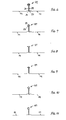
- the profiled sheet 11 shown in Figure 1 is a standing seam profiled sheet for a roofing.
- the profiled sheet 11 has a first longitudinal edge 13, parallel to it a second edge 15 and in between a clothing surface 16.
- the orientation of the edges 13, 15 can also depend on the parallel arrangement differ.
- Adjoining the first edge 13 is a hook-shaped cross section Formation 17 is formed, which projects to the outside 19 of the profiled sheet 11. It encompasses an interior 21 that is open toward the rear of the profiled sheet 11 partially.
- An opening slot 23 remains open, through which the Head formation 25 of an adjacent profiled sheet 11 into the interior 21 can be pushed in.
- At the second edge 15 there is a mounting flange 27 designed to rest on a substructure, not shown.
- this mounting flange 27 is not a conventional sheet metal sheet provided holder web 31 formed.
- a Head 25 trained At the outer end of this holder web 31 is a Head 25 trained.
- the head formation 25 is designed such that it with the Forming 17 of a second profiled sheet 11 can be gripped.
- This head training 25 and a shape 17 of an adjacent one placed over the head formation 25 Profile sheet 11 can be pressed together.
- Between the head formation 25 and the clothing surface 16 and between the formation 17 and the Clothing surface 16 has a standing seam web 29, 30 in each case.
- a holder web 31 is formed between the Head formation 25 and the mounting flange 27, a holder web 31 is formed.
- An elongated perforation 33 is formed in the fastening flange 27. Through the Oblong perforation and possibly through an insulation layer, not shown screws 37 extend therethrough. Between the standing seam webs 29, 30 and Clothing surface 16 is formed a bead 35 in which the heads 39 of the screws Find 37 place. For this purpose, the bead 35 is only adjacent to the standing seam web 29 required at the first edge 13. In the other standing seam web 30 is predominant for aesthetic reasons, a bead 35 is also formed symmetrically to this.
- a profiled sheet 12 is shown, in which the Clothing surface 16 in a plane between the plane of the fastening flange 27 and the head formation 25.
- the holding web 32 is one in FIG
- the amount is wider than the holding web 31 in FIG. 1. This is the amount Clothing surface 16 over the substructure, not shown in Figure 2.
- a support plane 49 is shown, the outer surface of a Substructure corresponds.
- a rear ventilation 51 between the profiled sheet 12 and the Substructure has a void thickness of this chosen amount.
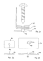
- FIG 5 In Figure 5 are the above-mentioned screw 37, a washer 41 and one Support washer 42 with the fastening flange 27 between the washers 41, 42 shown. So that the profiled sheet web is held with the screws 37, the However, linear expansion can change under the influence of temperature a spacer ring 43 is provided between the disks 41, 42. Under the Mounting flange 27, a washer 41 is provided and over the Mounting flange 27 a washer 42. The spacer ring 43 holds the two Disks at a predetermined distance from each other, at least the sheet thickness the mounting flange 27 corresponds.
- the washer 41 and the washer 42 each have one für Stammötechnisch45. This has an opening width that is slightly larger than that Cross section of the shaft of the screw 37.
- the head of the screw 37 is of course, larger than the opening width of the passage opening 45.
- the exemplary embodiment shown is part of the washer 41 is.
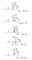
- the standing seam heads 47 are shown circular in the first two figures. This is also the most appropriate shape of the standing seam heads 47.
- Standing seam heads 47 A large number of further possible forms of Standing seam heads 47 shown. If the illustrated head training 25 in Essentially correspond to the interior 21 of the formation 17, so is one divergent shape possible, but preferably the head formation 25 and the formation 17 mutually along at least two, advantageously along three Longitudinal lines correspond. The pressed formation 17 lies on these lines Head training 25.
- the shape 17 in the Head training 25 it is essential that the shape 17 in the Head training 25 can be hung. This is usually the formation 17 of a sheet metal sheet 11 or 12 to be fastened onto the head formation 25 already placed on a substructure and attached sheet metal sheeting.
- the formation 17 is with the opening slot 23 over the head formation 25 pressed so that the head formation 25 through the opening slot 23 in the Interior 21 of the formation 17 arrives.
- the second edge 15 of the fastening sheet metal sheet held at a distance from the substructure. If the Forming 25 encloses the head formation 15, the profiled sheet is on the Filed substructure and attached to it with screws 37.
- the standing seam heads 47 can therefore have a wide variety of shapes, provided that they allow this assembly process. The final shape of the standing seam heads 47 can only be made by a subsequent one Pressing process are formed.
- a sandwich element 53 is shown in FIG.
- the metal outer skin 55 of the Sandwich element 53 is a profiled sheet web according to the invention.
- the liner 57 can be foamed. In the example, however, it consists of a mineral Fiber insulation layer, e.g. a rock wool or glass wool plate.
- the inner skin 59 in the exemplary embodiment according to FIG. 18 consists of a profiled sheet.
- the Sandwich element 53 is with an overlapping joint in the insulating Intermediate layer 57 is formed.
- the inner profile sheets are in the joints elastic sealing strips 61 sealed against each other. This is one largely vapor-tight construction possible, which is a compact Warm roof construction enables.
- the sandwich elements 53 can in one A visible surface on the inside of the building, a vapor barrier, one Thermal insulation and an outer skin can be added.
- the distance between the Inner skin 59 and outer skin 55 is only by the insulating material Liner 57 maintained. Therefore, except for the screws 37, which the Tie outer skin 55 to the substructure, no thermal bridges.
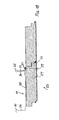
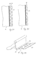
- FIG. 19 A cross-section through a sheet metal sheet particularly suitable for sandwich elements 14 is shown shortened in FIG. 19.
- On the left edge is a shape 17 with an interior 21 wide open downward. After that is the standing seam web 29, then a corrugation 35 and the rest that follows Clothing surface 19 formed.
- On the right edge of the clothing surface 19 is the Standing seam bridge 30, followed by the head formation 25 and from this down again the retaining web 31 is formed.
- the mounting flange 27 executed in double sheet thickness.
- the fastening flange 27 is the 1 mm thick sheet of the profiled sheet 14 once folded, with a gap of approx. 1 mm open between the two layers.
- the formation 17 is only with a head formation after pressing this connected.
- the formation 17 can be perpendicular to the plane of the Clothing surface 19 are placed over the head training 25.
- the Profile sheet web 14 with the standing seam web 29 to the retaining web 31 of the previous one Profile sheet web 14 are pushed so that the edge between the standing seam web 29th and the formation 17 comes under the projecting point of the head formation 25.
- the standing seam or the standing seam can later be pressed with a machine become.
- the same configuration of the profiled sheet web 14 is shown in perspective in FIG.
- the standing seam webs 29 and 30 left and right of the clothing surface 19 the head formation 25, the retaining web 31 and the mounting flange 27 are the perforations 33 in the mounting flange 27 and the screws 37, as well as the washer 41 and the washer 42 are shown.
- the perforation corresponds to that in the profiled sheets 11 and 12 according to FIG. 1 and 3 or 2 and 4 perforations 33.
- a grid of 6 cm there is a 4th cm long slot and a distance between the holes 33 of 2 cm is provided.
- the hole width is 8 mm in the exemplary embodiment according to FIGS. 19 and 20 or 9 mm in the other two embodiments mentioned.
- the mounting flange 27 Washer 41 arranged. It has a rectangular passage opening 45 and a spacer 43 (cf. Figure 23). The spacer protrudes the top of the washer 41 by 3 mm, which corresponds to the thickness of the mounting flange 27. Because the thickness of the Give up the mounting flange 27 slightly due to the two-layer design can, the spacer 43 no longer has to be a space between the Secure washer 41 and washer 43.
- the washer 41 is made of plastic. It therefore glides on it Profile sheet web 14 relatively light. The sliding movement is by the spacers 33 and the perforation 33, since the spacers 43 penetrate the perforation 33.
- Support disc 42 is provided with a stainless steel plate, the corners of which are rounded (see Figure 22).
- the passage openings 45 in the support washer are circular. Both Passage openings have a diameter of 6.7, so that the screws 37 with a shaft diameter of 6.5 can be easily screwed through.
- FIGS. 19 to 23 The currently preferred embodiment of a profiled sheet web according to the invention 14 and their fastening parts 41, 42, 37 are shown in FIGS. 19 to 23.
- This The profiled sheet web 14 only adjoins the standing seam web 29 near the first one Edge 13 a bead 35. On the other side of the clothing surface 19 is subsequently no bead is formed on the standing seam web 30. This favors them Use in a sandwich element.
- the mounting flange 27 is also directly on formed the sheet metal forming the clothing surface. This requires the Slidability of the mounting flange relative to the fasteners, i.e. the screws 37, the washers 41 and the washers 42.
- the mounting flange 27 can also be moved on one Profile sheet 10 to be crimped.
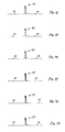
- Figures 24 to 33 are a number of crimped Fastening flanges shown.
- folding mounting flanges 27 is advantageous to ensure that the common fold 63 a detachment of the Fastening flange 27 prevented from the remaining sheet metal sheet 10. This allows a direct mounting of the sheet metal sheets 8 on a substructure, or Use of the profiled sheet 10 as the outer skin 55 of a sandwich element 53.
- Foldings 63 of the sheet metal of the mounting flange 27 with the sheet of metal Clothing surface can in the area of the mounting flange 27, in the area of Retaining web 31 or the head training 25 lie. You can also use a bead 35 between the standing seam web 30 in the head formation 25 and the clothing surface 19 be arranged.
- the fold advantageously leaves a longitudinal displacement between the fastening flange 27 and the clothing surface 19. However, it can also oblong holes 33 may be formed in a crimped fastening flange.
- the Folding 63 can also be created when profiling sheet metal sheet 10.
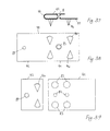
- FIG. 34 shows a top view of a fastening flange 27 with two rows 34 of Slots 33.
- the elongated holes of one row 34 are opposite the elongated holes the other row arranged so offset that the sheet metal webs between the Elongated holes 33 in one row approximately in the middle next to the elongated holes 33 in the other row 34 lie.
- the distance between the one, e.g. lower end of an elongated hole 33 of the one row 34 and the same end of an adjacent elongated hole 33 of the other Row 34 is always practically the same and is called the grid spacing.
- the elongated hole can be longer than the grid spacing.
- the grid spacing can be the same at the same displacement distance can be chosen smaller and therefore the sheet metal on relatively narrow Fastening strips, e.g. Raising the structure to be attached.
- FIG 35 a mounting flange 27 is shown, which only one row 34 of Has elongated holes 33.
- the comparison of Figures 34 and 35 clearly shows that with the same design of the rows of slots 34 with a single row 34 a screw can only be screwed in twice as far, if the movability of the sheet metal should not be impaired.
- the mounting flange 27 consists of a folded sheet metal edge of the profiled sheet 11. This is the Mounting flange 27 more resistant to bending than in a single-layer training. This has the Advantage that the mounting flange 27 can be bent less and therefore the Slidability relative to the fasteners remains guaranteed.
- a mounting bracket 44 is shown. This is from one Stainless steel sheet piece shaped and has one under the mounting flange 27 to pushing washer part 41 and one over the mounting flange 27 sliding washer part 42. These two parts are around the Fixing flange connected around.
- the brackets 44 has Washer part 41 punched out and bent down, protruding prongs 46, which can be pressed into a thermal insulation layer.
- the Clip 44 shown stretched.
- FIG. 39 shows a washer 41 and a washer 42 for one Profile sheet 11 with two rows 34 of elongated holes 33 in the mounting flange 27.
- the washer 41 has twice next to each other at a distance from the rows of Elongated holes three holes each.
- the middle hole 82 is intended for reception the bolt-shaped fastener.
- the other two holes 83 are in one Distance from each other, which corresponds to the grid spacing of the elongated holes 33. Through these two holes 83 extend prongs 46 or claws on the Washer 42 are arranged.
- the washer 42 has an edge Hole 84 through which the fastener can be passed.
- two teeth 46 are punched out and bent, which through the Elongated holes 33 in the second row 34 and the holes 83 provided therefor in the Washer 41 can be pressed into the insulating layer 81.
- By can rotate the support plate 42 by 180 degrees, whether that bolt-shaped fasteners in one or the other row 34 of Elongated holes 33 is to be inserted in the fastening flange 27.
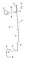
- FIG. 40 shows a section through a roof structure.
- At 71 is one Designated steel girder on which a trapezoidal sheet 73 rests.
- the trapezoidal sheet has Hochsicken 75 and Tiefsicken 77.
- Over the Hochsicken is a vapor barrier layer 79th stretched and glued on.
- On top of this is a mineral fiber thermal insulation layer 81 hung up.
- the sheet metal sheets 11 are transverse to Direction of the beads of the trapezoidal sheet 73 relocated.
- FIG. 41 shows the same section as in FIG. 40.
- Fastening screws 37 shown. These have two threaded sections 91 and 92 on.
- a first threaded section 91 is connected to the screw tip formed, a second 92 at a distance from the first 91 and at a distance from the Head of screw.
- Both between the second thread section 92 near the head and the head of the screw as well as on the head-facing side of the first Threaded section 91 is an idle in the shaft area formed by the Diameter of the shaft corresponds approximately to that of the thread core.
- the shaft can be freely rotated in the hole and slidable in the direction of the shaft.
- the first threaded section 91 is included screwed screw 37 under the support plate 75, the second threaded section 92 lies under the washer 41.
- the screw 37 is through the washer 41 through bolted.
- a thread is formed in the washer 41. This will easiest formed during screwing in by the screw 37 itself.
- the edge of the last thread revolution of the second thread section 92 is behind Fasten the screw from below to the edge of the hole in the washer on. When unscrewing the screw, both the first thread 91 and that second thread 92 in the formed in the trapezoidal sheet 75 and in the washer 41 Threads are inserted. This happens only with a small probability movements of screw 37 due to wind and temperature. This is also deliberate difficult to achieve.
Landscapes
- Engineering & Computer Science (AREA)
- Architecture (AREA)
- Civil Engineering (AREA)
- Structural Engineering (AREA)
- Mechanical Engineering (AREA)
- Roof Covering Using Slabs Or Stiff Sheets (AREA)
- Treatment Of Fiber Materials (AREA)
- Connection Of Plates (AREA)
- Polishing Bodies And Polishing Tools (AREA)
Abstract
Description
- Figur 1:
- eine perspektivische Darstellung einer erfindungsgemässen Profilblechbahn, ohne Hinterlüftung,
- Figur 2:
- eine perspektivische Darstellung einer erfindungsgemässen Profilblechbahn, mit Hinterlüftung,
- Figur 3:
- einen Querschnitt durch eine Profilblechbahn gemäss Figur 1 im Verband mit benachbarten Profilblechbahnen,
- Figur 4:
- einen Querschnitt durch eine Profilblechbahn gemäss Figur 2 im Verband mit benachbarten Profilblechbahnen,
- Figur 5:
- einen Detailschnitt durch eine Befestigungsstelle,
- Figuren 6 bis 17:
- schematische Schnitte durch Stehfälze mit unterschiedlichen Gestaltungen der Falzköpfe,
- Figur 18:
- ein Querschnitt durch eine Sandwich-Dachplatte
- Figur 19:
- einen Querschnitt durch eine für Sandwich-Dachplatten besonders geeignete Profilblechbahn,
- Figur 20:
- die Profilblechbahn nach Figur 19 in einer perspektivischen Ansicht,
- Figur 21:
- bevorzugte Befestigungselemente für eine erfindungsgemässe Profilblechbahn,
- Figur 22:
- die Auflagescheibe gemäss Figur 21,
- Figur 23:
- die Unterlagsscheibe gemäss Figur 21,
- Figuren 24 bis 33:
- mit der Blechbahn der Bekleidungsfläche verfalzte Befestigungsflansche,
- Figur 34:
- einen Schnitt durch den Steg eines Profilblechs mit zwei Reihen von Langlöchern im Befestigungsflansch,
- Figur 35:
- einen Schnitt durch den Steg eines Profibleches mit einer Reihe von Langlöchern im Befestigungsflansch,
- Figur 36:
- eine perspektivische Skizze eines Ausschnittes eines Profilbleches mit zwei Reihen von Langlöchern,
- Figur 37:
- eine Befestigungsklammer mit Verschiebesicherung im Querschnitt,
- Figur 38:
- die Befestigungsklammer nach Fig. 37 in ungefaltetem Zustand,
- Figur 39:
- eine Unterlagsscheibe und eine Auflagescheibe, insbesondere für ein Profilblech mit zwei Langlochreihen
- Figur 40:
- einen Schnitt durch einen Dachaufbau mit einer Eindeckung aus den erfindungsgemässen Profilblechen,
- Figur 41:
- einen Schnitt gemäss Figur 40, jedoch mit anderen Befestigungsschrauben.
Claims (13)
- Profilblechbahn (10,11,12,14) mit einer Bekleidungsfläche (19) zwischen einem ersten und einem zweiten längsgerichteten Rand (13, bzw. 15), einer zur Aussenseite (16) der Profilblechbahn (10,11,12,14) vorspringenden und auf der Innenseite konkaven Ausformung (17) beim ersten Rand (13), einer von der konkaven Ausformung (17) einer angrenzenden zweiten Profilblechbahn (10,11,12,14) umgreifbaren Kopfausbildung (25) und einem auf einen ebenen Unterbau auflegbaren Befestigungsflansch (27) beim zweiten Rand der Profilblechbahn (10,11,12,14), und im Befestigungsflansch (27) parallel zur Profilrichtung ausgerichtete Langlöcher (33),
dadurch gekennzeichnet, dass die Langlöcher (33) in einem Rasterabstand von höchstens 210 mm in wenigstens einer parallel zur Profilrichtung angeordneten Reihe ausgebildet sind. - Profilblechbahn nach Anspruch 1, dadurch gekennzeichnet, dass die Langlöcher (33) in einem Rasterabstand von höchstens 120 mm, vorzugsweise höchstens 110 mm, besonders bevorzugt höchstens 100 mm ausgebildet sind.
- Priflblechbahn nach einem der Anspüche 1 oder 2, dadurch gekennzeichnet, dass im Befestigungsflansch (27) zwei gegeneinander versetzte Reihen von Langlöchern (33) nebeneinander ausgebildet sind.
- Profilblechbahn nach einem der Ansprüche 1 bis 3, dadurch gekennzeichnet, dass der Befestigungsflansch (27) einstückig an der die Bekleidungsfläche (19) bildenden Blechbahn ausgebildet ist.
- Profilblechbahn nach einem der Ansprüche 1 bis 3, dadurch gekennzeichnet, dass die Bekleidungsfläche (19) aus einer ersten Blechbahn und der Befestigungsflansch (27) aus einer zweiten Blechbahn gebildet ist und die zweite Blechbahn mit der ersten Blechbahn verfalzt ist.
- Profilblechbahn nach einem der Ansprüche 1 bis 5, dadurch gekennzeichnet, dass zwischen der Kopfausbildung (25) und der Bekleidungsfläche (19), zwischen der Ausformung (17) und der Bekleidungsfläche (19) wie auch zwischen der Kopfausbildung (25) und dem Befestigungsflansch (27) jeweils ein Steg (29,30,31,32) ausgebildet ist.
- Profilblechbahn nach Anspruch 6, dadurch gekennzeichnet, dass angrenzend an den Steg in der Bekleidungsfläche eine Sicke () ausgegebildet ist und der Steg (31,32) zwischen Kopfausbildung (25) und Befestigungsflansch (27) breiter ist als der Steg (29) zwischen Ausformung (17) und Sicke ().
- Profilblechbahn nach Anspruch 6 oder 7, dadurch gekennzeichnet, dass der Befestigungsflansch (27) und die Bekleidungsfläche (19) praktisch in derselben Ebene liegen.
- Profilblechbahn nach Anspruch 6 oder 7, dadurch gekennzeichnet, dass die Bekleidungsfläche (19) in einer Ebene zwischen der Ebene des Befestigungsflansches (27) und der Kopfausbildung (25) liegt.
- Profilblechbahn nach einem der Ansprüche 1 bis 9, dadurch gekennzeichnet, dass im Bereich des Befestigungsflansches wenigstens zwei Lagen Blech vorhanden sind.
- Sandwichelement (53) mit einer metallenen Aussenhaut (55), einer wärmedämmenden Zwischenlage (57) und einer Innenhaut (59), dadurch gekennzeichnet, dass die Aussenhaut (55) eine Profilblechbahn (10,11,12,14) nach einem der Ansprüche 1 bis 10 ist.
- Dachaufbau mit einem Hochsicken (75) einer bestimmten Breite und Tiefsicken (77) aufweisenden, tragenden Trapezblech (73), über dem Trapezblech einer Dampfdiffusionssperrschicht (79) und darüber einer Wärmedämmschicht (81), und über der Wärmedämmschicht einer Profilblecheindeckung (11), welche mit bolzenförmigen Befestigungsmitteln (37) mit den Hochsicken (75) des Trapezbleches (73) verbunden ist, dadurch gekennzeichnet, dass das Profilblech (11) ein Profilblech gemäss einem der Ansprüche 1 bis 10 ist und der Rasterabstand der Langlöcher (33) höchstens der Breite der Hochsicken (75) entspricht.
- Dachaufbau nach Anspruch 12, dadurch gekennzeichnet, dass das Profilblech mit Schrauben am Trapezblech befestigt ist, welche einen ersten Gewindeabschnit aufweisen, der durch das Trapezblech hindurchgeschraubt ist, und einen zweiten Gewindeabschnitt, der durch eine Unterlagsscheibe unter dem Befestigugnsrand des Profilbleches hindurchgeschraubt ist, und dass sich sowohl die Unterlagsscheibe als auch das Trapezblech in einem Bereich hinter dem jeweiligen Gewindeabschnitt befinden, in welchem der Schaft der Schraube einen Durchmesser aufweist, der dem Durchmesser des Gewindekerns entspricht.
Applications Claiming Priority (2)
| Application Number | Priority Date | Filing Date | Title |
|---|---|---|---|
| CH6432001 | 2001-04-04 | ||
| CH20010643 | 2001-04-04 |
Publications (3)
| Publication Number | Publication Date |
|---|---|
| EP1249556A2 true EP1249556A2 (de) | 2002-10-16 |
| EP1249556A3 EP1249556A3 (de) | 2002-12-18 |
| EP1249556B1 EP1249556B1 (de) | 2005-03-09 |
Family
ID=4525581
Family Applications (1)
| Application Number | Title | Priority Date | Filing Date |
|---|---|---|---|
| EP02405050A Expired - Lifetime EP1249556B1 (de) | 2001-04-04 | 2002-01-28 | Profilblechbahn |
Country Status (3)
| Country | Link |
|---|---|
| EP (1) | EP1249556B1 (de) |
| AT (1) | ATE290634T1 (de) |
| DE (1) | DE50202408D1 (de) |
Cited By (5)
| Publication number | Priority date | Publication date | Assignee | Title |
|---|---|---|---|---|
| EP2423405A1 (de) | 2010-08-26 | 2012-02-29 | HSW Monteco GmbH | Stehfalzeindeckung |
| CN102581083A (zh) * | 2012-02-01 | 2012-07-18 | 中国十九冶集团有限公司 | 不规则屋面瓦的制作方法 |
| ITMI20130293A1 (it) * | 2013-02-28 | 2014-08-29 | Schatzer Alois S R L | Graffa di ancoraggio di lamiere a travature di coperture, tetti e simili con accoppiamento relativo tra piano di base e piano di appoggio libero nella direzione longitudinale |
| CN108331267A (zh) * | 2018-03-14 | 2018-07-27 | 森特士兴集团股份有限公司 | 一种金属屋面板抗风固定装置 |
| CN116104256A (zh) * | 2023-02-22 | 2023-05-12 | 精工工业建筑系统集团有限公司 | 一种用于无檩屋面系统的新型压型薄板 |
Citations (1)
| Publication number | Priority date | Publication date | Assignee | Title |
|---|---|---|---|---|
| US5535567A (en) | 1994-10-05 | 1996-07-16 | Razor Enterprises, Inc. | Standing seam roofing panel |
Family Cites Families (6)
| Publication number | Priority date | Publication date | Assignee | Title |
|---|---|---|---|---|
| DE2136584A1 (de) * | 1971-07-22 | 1973-02-08 | Hunter Douglas | Paneel fuer wand- oder deckenverkleidung |
| US4435938A (en) * | 1981-11-12 | 1984-03-13 | National Gypsum Company | Vinyl siding attachment |
| US5584153A (en) * | 1994-03-29 | 1996-12-17 | Loadmaster Systems, Inc. | Composite roof system with an improved anchoring mechanism |
| US5768844A (en) * | 1996-12-16 | 1998-06-23 | Norandex | Building siding panels and assemblies |
| DE29817127U1 (de) * | 1998-09-24 | 1999-01-07 | Fischer Profil GmbH, 57250 Netphen | Dacheindeckungselement |
| GB2345705B (en) * | 1999-01-13 | 2003-06-18 | Talfab Holdings Ltd | Improvements in or relating to panels |
-
2002
- 2002-01-28 DE DE50202408T patent/DE50202408D1/de not_active Expired - Fee Related
- 2002-01-28 EP EP02405050A patent/EP1249556B1/de not_active Expired - Lifetime
- 2002-01-28 AT AT02405050T patent/ATE290634T1/de not_active IP Right Cessation
Patent Citations (1)
| Publication number | Priority date | Publication date | Assignee | Title |
|---|---|---|---|---|
| US5535567A (en) | 1994-10-05 | 1996-07-16 | Razor Enterprises, Inc. | Standing seam roofing panel |
Cited By (8)
| Publication number | Priority date | Publication date | Assignee | Title |
|---|---|---|---|---|
| EP2423405A1 (de) | 2010-08-26 | 2012-02-29 | HSW Monteco GmbH | Stehfalzeindeckung |
| CH703646A1 (de) * | 2010-08-26 | 2012-02-29 | Hsw Monteco Gmbh | Stehfalzeindeckung. |
| CN102581083A (zh) * | 2012-02-01 | 2012-07-18 | 中国十九冶集团有限公司 | 不规则屋面瓦的制作方法 |
| ITMI20130293A1 (it) * | 2013-02-28 | 2014-08-29 | Schatzer Alois S R L | Graffa di ancoraggio di lamiere a travature di coperture, tetti e simili con accoppiamento relativo tra piano di base e piano di appoggio libero nella direzione longitudinale |
| EP2772595A1 (de) * | 2013-02-28 | 2014-09-03 | Schatzer Alois S.r.l. | Klemme zur Befestigung von metallischen Platten an Balken eines Dachsystems, eines Dachs oder ähnlichem mit einer Fuge zur in der longitudinaler Richtung frei verschiebbaren Verbindung einer Basisfläche mit einer Lagerfläche |
| CN108331267A (zh) * | 2018-03-14 | 2018-07-27 | 森特士兴集团股份有限公司 | 一种金属屋面板抗风固定装置 |
| CN108331267B (zh) * | 2018-03-14 | 2023-12-15 | 森特士兴集团股份有限公司 | 一种金属屋面板抗风固定装置 |
| CN116104256A (zh) * | 2023-02-22 | 2023-05-12 | 精工工业建筑系统集团有限公司 | 一种用于无檩屋面系统的新型压型薄板 |
Also Published As
| Publication number | Publication date |
|---|---|
| EP1249556A3 (de) | 2002-12-18 |
| EP1249556B1 (de) | 2005-03-09 |
| ATE290634T1 (de) | 2005-03-15 |
| DE50202408D1 (de) | 2005-04-14 |
Similar Documents
| Publication | Publication Date | Title |
|---|---|---|
| DE4242530C2 (de) | Bauelement für Wände, Decken oder Dächer von Bauwerken | |
| DE2608788C2 (de) | Gebäudewand, die sich bei extremen Druckverhältnissen einwärts oder auswärts aus ihrem Tragrahmen löst | |
| DE69303627T2 (de) | Wasserdichte Dachabdeckvorrichtung | |
| DE10044286A1 (de) | Dach- und Deckensystem | |
| DE2700468C2 (de) | Wärmedämmende Innenverkleidung für von Sparren getragene Dächer | |
| EP1426520B1 (de) | Kombination einer Platte oder eines Paneels und zumindest einer Befestigungsanordnung sowie Verfahren zur Befestigung einer Platte oder eines Paneels | |
| EP1249556B1 (de) | Profilblechbahn | |
| EP0849420A1 (de) | Wärmegedämmte Gebäudehülle | |
| EP0918127B1 (de) | Türfutter und Montagevorrichtung | |
| EP1088944A2 (de) | Fugendichtung | |
| DE69000122T2 (de) | Dichtungsschuerze zur eindeckung von uebergaengen zwischen flachen und profilierten dachteilen. | |
| DE2148872A1 (de) | Einrichtung zum befestigen von verkleidungen oder bespannungen auf beliebigen oberflaechen, wie z. b. einer wand, decke o. dgl | |
| DE4304386C2 (de) | Halterung für ein Dachfenster | |
| DE68914009T2 (de) | Befestigungsvorrichtung für Dachziegel. | |
| DE7720341U1 (de) | Als baukonstruktionselement verwendbare platte | |
| DE69924976T2 (de) | Verbesserung an dachein- oder dachabdeckung | |
| WO1990007037A1 (de) | Verbundelement für bauzwecke | |
| DE3941216A1 (de) | Firstziegelhalterung | |
| DE10161637C1 (de) | Dachdämmplatte | |
| DE3641613A1 (de) | Befestigungselement | |
| DE2325281A1 (de) | Metalltraegerelement fuer bauwerksdecken und aus diesem metalltraegerelement und einer betonschicht gebildeten bauwerksdecke | |
| AT407174B (de) | Randstreifen an dachtraufen | |
| DE3203199A1 (de) | Aufbau eines flachdachrandes | |
| DE8632630U1 (de) | Befestigungselement | |
| EP1999318B1 (de) | Halteschiene für dachbahnen |
Legal Events
| Date | Code | Title | Description |
|---|---|---|---|
| PUAI | Public reference made under article 153(3) epc to a published international application that has entered the european phase |
Free format text: ORIGINAL CODE: 0009012 |
|
| AK | Designated contracting states |
Kind code of ref document: A2 Designated state(s): AT BE CH CY DE DK ES FI FR GB GR IE IT LI LU MC NL PT SE TR |
|
| AX | Request for extension of the european patent |
Free format text: AL;LT;LV;MK;RO;SI |
|
| PUAL | Search report despatched |
Free format text: ORIGINAL CODE: 0009013 |
|
| AK | Designated contracting states |
Kind code of ref document: A3 Designated state(s): AT BE CH CY DE DK ES FI FR GB GR IE IT LI LU MC NL PT SE TR |
|
| AX | Request for extension of the european patent |
Free format text: AL;LT;LV;MK;RO;SI |
|
| 17P | Request for examination filed |
Effective date: 20030522 |
|
| 17Q | First examination report despatched |
Effective date: 20030724 |
|
| AKX | Designation fees paid |
Designated state(s): AT BE CH CY DE DK ES FI FR GB GR IE IT LI LU MC NL PT SE TR |
|
| GRAP | Despatch of communication of intention to grant a patent |
Free format text: ORIGINAL CODE: EPIDOSNIGR1 |
|
| GRAS | Grant fee paid |
Free format text: ORIGINAL CODE: EPIDOSNIGR3 |
|
| GRAA | (expected) grant |
Free format text: ORIGINAL CODE: 0009210 |
|
| AK | Designated contracting states |
Kind code of ref document: B1 Designated state(s): AT BE CH CY DE DK ES FI FR GB GR IE IT LI LU MC NL PT SE TR |
|
| PG25 | Lapsed in a contracting state [announced via postgrant information from national office to epo] |
Ref country code: IT Free format text: LAPSE BECAUSE OF FAILURE TO SUBMIT A TRANSLATION OF THE DESCRIPTION OR TO PAY THE FEE WITHIN THE PRESCRIBED TIME-LIMIT;WARNING: LAPSES OF ITALIAN PATENTS WITH EFFECTIVE DATE BEFORE 2007 MAY HAVE OCCURRED AT ANY TIME BEFORE 2007. THE CORRECT EFFECTIVE DATE MAY BE DIFFERENT FROM THE ONE RECORDED. Effective date: 20050309 Ref country code: IE Free format text: LAPSE BECAUSE OF FAILURE TO SUBMIT A TRANSLATION OF THE DESCRIPTION OR TO PAY THE FEE WITHIN THE PRESCRIBED TIME-LIMIT Effective date: 20050309 Ref country code: FI Free format text: LAPSE BECAUSE OF FAILURE TO SUBMIT A TRANSLATION OF THE DESCRIPTION OR TO PAY THE FEE WITHIN THE PRESCRIBED TIME-LIMIT Effective date: 20050309 |
|
| REG | Reference to a national code |
Ref country code: GB Ref legal event code: FG4D Free format text: NOT ENGLISH |
|
| REG | Reference to a national code |
Ref country code: CH Ref legal event code: EP |
|
| REG | Reference to a national code |
Ref country code: IE Ref legal event code: FG4D Free format text: GERMAN |
|
| REF | Corresponds to: |
Ref document number: 50202408 Country of ref document: DE Date of ref document: 20050414 Kind code of ref document: P |
|
| REG | Reference to a national code |
Ref country code: CH Ref legal event code: NV Representative=s name: RIEDERER HASLER & PARTNER PATENTANWAELTE AG |
|
| GBT | Gb: translation of ep patent filed (gb section 77(6)(a)/1977) |
Effective date: 20050421 |
|
| PG25 | Lapsed in a contracting state [announced via postgrant information from national office to epo] |
Ref country code: GR Free format text: LAPSE BECAUSE OF FAILURE TO SUBMIT A TRANSLATION OF THE DESCRIPTION OR TO PAY THE FEE WITHIN THE PRESCRIBED TIME-LIMIT Effective date: 20050609 Ref country code: DK Free format text: LAPSE BECAUSE OF FAILURE TO SUBMIT A TRANSLATION OF THE DESCRIPTION OR TO PAY THE FEE WITHIN THE PRESCRIBED TIME-LIMIT Effective date: 20050609 |
|
| PG25 | Lapsed in a contracting state [announced via postgrant information from national office to epo] |
Ref country code: ES Free format text: LAPSE BECAUSE OF FAILURE TO SUBMIT A TRANSLATION OF THE DESCRIPTION OR TO PAY THE FEE WITHIN THE PRESCRIBED TIME-LIMIT Effective date: 20050620 |
|
| PG25 | Lapsed in a contracting state [announced via postgrant information from national office to epo] |
Ref country code: PT Free format text: LAPSE BECAUSE OF FAILURE TO SUBMIT A TRANSLATION OF THE DESCRIPTION OR TO PAY THE FEE WITHIN THE PRESCRIBED TIME-LIMIT Effective date: 20050907 |
|
| REG | Reference to a national code |
Ref country code: IE Ref legal event code: FD4D |
|
| PLBE | No opposition filed within time limit |
Free format text: ORIGINAL CODE: 0009261 |
|
| STAA | Information on the status of an ep patent application or granted ep patent |
Free format text: STATUS: NO OPPOSITION FILED WITHIN TIME LIMIT |
|
| ET | Fr: translation filed | ||
| PG25 | Lapsed in a contracting state [announced via postgrant information from national office to epo] |
Ref country code: MC Free format text: LAPSE BECAUSE OF NON-PAYMENT OF DUE FEES Effective date: 20060131 Ref country code: LU Free format text: LAPSE BECAUSE OF NON-PAYMENT OF DUE FEES Effective date: 20060131 |
|
| 26N | No opposition filed |
Effective date: 20051212 |
|
| PG25 | Lapsed in a contracting state [announced via postgrant information from national office to epo] |
Ref country code: SE Free format text: LAPSE BECAUSE OF FAILURE TO SUBMIT A TRANSLATION OF THE DESCRIPTION OR TO PAY THE FEE WITHIN THE PRESCRIBED TIME-LIMIT Effective date: 20050609 |
|
| PG25 | Lapsed in a contracting state [announced via postgrant information from national office to epo] |
Ref country code: TR Free format text: LAPSE BECAUSE OF FAILURE TO SUBMIT A TRANSLATION OF THE DESCRIPTION OR TO PAY THE FEE WITHIN THE PRESCRIBED TIME-LIMIT Effective date: 20050309 |
|
| PG25 | Lapsed in a contracting state [announced via postgrant information from national office to epo] |
Ref country code: CY Free format text: LAPSE BECAUSE OF FAILURE TO SUBMIT A TRANSLATION OF THE DESCRIPTION OR TO PAY THE FEE WITHIN THE PRESCRIBED TIME-LIMIT Effective date: 20050309 |
|
| PGFP | Annual fee paid to national office [announced via postgrant information from national office to epo] |
Ref country code: AT Payment date: 20090115 Year of fee payment: 8 |
|
| PGFP | Annual fee paid to national office [announced via postgrant information from national office to epo] |
Ref country code: DE Payment date: 20090122 Year of fee payment: 8 Ref country code: NL Payment date: 20090114 Year of fee payment: 8 |
|
| PGFP | Annual fee paid to national office [announced via postgrant information from national office to epo] |
Ref country code: CH Payment date: 20090107 Year of fee payment: 8 Ref country code: GB Payment date: 20090122 Year of fee payment: 8 |
|
| PGFP | Annual fee paid to national office [announced via postgrant information from national office to epo] |
Ref country code: BE Payment date: 20090219 Year of fee payment: 8 |
|
| PGFP | Annual fee paid to national office [announced via postgrant information from national office to epo] |
Ref country code: FR Payment date: 20090115 Year of fee payment: 8 |
|
| BERE | Be: lapsed |
Owner name: *SCHNEIDER WALTER SENIOR Effective date: 20100131 |
|
| REG | Reference to a national code |
Ref country code: NL Ref legal event code: V1 Effective date: 20100801 |
|
| REG | Reference to a national code |
Ref country code: CH Ref legal event code: PL |
|
| GBPC | Gb: european patent ceased through non-payment of renewal fee |
Effective date: 20100128 |
|
| REG | Reference to a national code |
Ref country code: FR Ref legal event code: ST Effective date: 20100930 |
|
| PG25 | Lapsed in a contracting state [announced via postgrant information from national office to epo] |
Ref country code: LI Free format text: LAPSE BECAUSE OF NON-PAYMENT OF DUE FEES Effective date: 20100131 Ref country code: FR Free format text: LAPSE BECAUSE OF NON-PAYMENT OF DUE FEES Effective date: 20100201 Ref country code: NL Free format text: LAPSE BECAUSE OF NON-PAYMENT OF DUE FEES Effective date: 20100801 Ref country code: CH Free format text: LAPSE BECAUSE OF NON-PAYMENT OF DUE FEES Effective date: 20100131 |
|
| PG25 | Lapsed in a contracting state [announced via postgrant information from national office to epo] |
Ref country code: AT Free format text: LAPSE BECAUSE OF NON-PAYMENT OF DUE FEES Effective date: 20100128 Ref country code: DE Free format text: LAPSE BECAUSE OF NON-PAYMENT OF DUE FEES Effective date: 20100803 |
|
| PG25 | Lapsed in a contracting state [announced via postgrant information from national office to epo] |
Ref country code: GB Free format text: LAPSE BECAUSE OF NON-PAYMENT OF DUE FEES Effective date: 20100128 |
|
| PG25 | Lapsed in a contracting state [announced via postgrant information from national office to epo] |
Ref country code: BE Free format text: LAPSE BECAUSE OF NON-PAYMENT OF DUE FEES Effective date: 20100131 |