EP1249305B1 - Stempelanordnung - Google Patents
Stempelanordnung Download PDFInfo
- Publication number
- EP1249305B1 EP1249305B1 EP02012625A EP02012625A EP1249305B1 EP 1249305 B1 EP1249305 B1 EP 1249305B1 EP 02012625 A EP02012625 A EP 02012625A EP 02012625 A EP02012625 A EP 02012625A EP 1249305 B1 EP1249305 B1 EP 1249305B1
- Authority
- EP
- European Patent Office
- Prior art keywords
- plunger
- functional element
- segments
- longitudinal axis
- punch
- Prior art date
- Legal status (The legal status is an assumption and is not a legal conclusion. Google has not performed a legal analysis and makes no representation as to the accuracy of the status listed.)
- Expired - Lifetime
Links
- 238000003780 insertion Methods 0.000 claims description 4
- 230000037431 insertion Effects 0.000 claims description 4
- 230000005540 biological transmission Effects 0.000 claims description 2
- 210000003128 head Anatomy 0.000 claims 2
- 210000001331 nose Anatomy 0.000 claims 1
- 229910052751 metal Inorganic materials 0.000 description 78
- 239000002184 metal Substances 0.000 description 78
- 239000000463 material Substances 0.000 description 25
- 239000002131 composite material Substances 0.000 description 23
- 238000000034 method Methods 0.000 description 19
- 239000006262 metallic foam Substances 0.000 description 17
- 238000004080 punching Methods 0.000 description 15
- 238000004519 manufacturing process Methods 0.000 description 11
- 239000011324 bead Substances 0.000 description 10
- 239000011162 core material Substances 0.000 description 8
- 239000006260 foam Substances 0.000 description 8
- 238000005520 cutting process Methods 0.000 description 7
- 239000004033 plastic Substances 0.000 description 6
- 229910045601 alloy Inorganic materials 0.000 description 5
- 239000000956 alloy Substances 0.000 description 5
- 230000000295 complement effect Effects 0.000 description 5
- 230000006835 compression Effects 0.000 description 5
- 238000007906 compression Methods 0.000 description 5
- 238000003825 pressing Methods 0.000 description 5
- FYYHWMGAXLPEAU-UHFFFAOYSA-N Magnesium Chemical compound [Mg] FYYHWMGAXLPEAU-UHFFFAOYSA-N 0.000 description 4
- 229910000831 Steel Inorganic materials 0.000 description 4
- 238000000576 coating method Methods 0.000 description 4
- 238000013461 design Methods 0.000 description 4
- 229910052749 magnesium Inorganic materials 0.000 description 4
- 239000011777 magnesium Substances 0.000 description 4
- 239000011159 matrix material Substances 0.000 description 4
- 239000010959 steel Substances 0.000 description 4
- 239000000853 adhesive Substances 0.000 description 3
- 230000001070 adhesive effect Effects 0.000 description 3
- 229910052782 aluminium Inorganic materials 0.000 description 3
- XAGFODPZIPBFFR-UHFFFAOYSA-N aluminium Chemical compound [Al] XAGFODPZIPBFFR-UHFFFAOYSA-N 0.000 description 3
- 239000000945 filler Substances 0.000 description 3
- 238000011049 filling Methods 0.000 description 3
- 238000005096 rolling process Methods 0.000 description 3
- 230000007704 transition Effects 0.000 description 3
- 229910000861 Mg alloy Inorganic materials 0.000 description 2
- 238000013459 approach Methods 0.000 description 2
- 230000015572 biosynthetic process Effects 0.000 description 2
- 238000005266 casting Methods 0.000 description 2
- 230000002349 favourable effect Effects 0.000 description 2
- 238000005187 foaming Methods 0.000 description 2
- 239000007769 metal material Substances 0.000 description 2
- 239000011148 porous material Substances 0.000 description 2
- 230000000750 progressive effect Effects 0.000 description 2
- 238000007493 shaping process Methods 0.000 description 2
- 229910000838 Al alloy Inorganic materials 0.000 description 1
- OKTJSMMVPCPJKN-UHFFFAOYSA-N Carbon Chemical compound [C] OKTJSMMVPCPJKN-UHFFFAOYSA-N 0.000 description 1
- 229910000975 Carbon steel Inorganic materials 0.000 description 1
- 241001494479 Pecora Species 0.000 description 1
- 239000004480 active ingredient Substances 0.000 description 1
- 238000004026 adhesive bonding Methods 0.000 description 1
- 238000005452 bending Methods 0.000 description 1
- 230000009286 beneficial effect Effects 0.000 description 1
- 238000005219 brazing Methods 0.000 description 1
- 229910052799 carbon Inorganic materials 0.000 description 1
- 239000001913 cellulose Substances 0.000 description 1
- 229920002678 cellulose Polymers 0.000 description 1
- 239000000919 ceramic Substances 0.000 description 1
- 239000011093 chipboard Substances 0.000 description 1
- 150000001875 compounds Chemical class 0.000 description 1
- 238000010276 construction Methods 0.000 description 1
- 230000007797 corrosion Effects 0.000 description 1
- 238000005260 corrosion Methods 0.000 description 1
- 238000013016 damping Methods 0.000 description 1
- 238000009826 distribution Methods 0.000 description 1
- 238000005516 engineering process Methods 0.000 description 1
- 238000002474 experimental method Methods 0.000 description 1
- 238000000605 extraction Methods 0.000 description 1
- 238000001125 extrusion Methods 0.000 description 1
- 239000011888 foil Substances 0.000 description 1
- 238000002844 melting Methods 0.000 description 1
- 230000008018 melting Effects 0.000 description 1
- 239000000203 mixture Substances 0.000 description 1
- 238000012986 modification Methods 0.000 description 1
- 230000004048 modification Effects 0.000 description 1
- 239000003973 paint Substances 0.000 description 1
- 239000000123 paper Substances 0.000 description 1
- 239000002984 plastic foam Substances 0.000 description 1
- 239000000843 powder Substances 0.000 description 1
- 230000036316 preload Effects 0.000 description 1
- 238000002360 preparation method Methods 0.000 description 1
- 238000007789 sealing Methods 0.000 description 1
- 238000005476 soldering Methods 0.000 description 1
- 239000007858 starting material Substances 0.000 description 1
- 238000003756 stirring Methods 0.000 description 1
- 238000005482 strain hardening Methods 0.000 description 1
- 238000007669 thermal treatment Methods 0.000 description 1
- 229920001187 thermosetting polymer Polymers 0.000 description 1
- 238000012549 training Methods 0.000 description 1
- 239000002023 wood Substances 0.000 description 1
Images


Classifications
-
- B—PERFORMING OPERATIONS; TRANSPORTING
- B23—MACHINE TOOLS; METAL-WORKING NOT OTHERWISE PROVIDED FOR
- B23P—METAL-WORKING NOT OTHERWISE PROVIDED FOR; COMBINED OPERATIONS; UNIVERSAL MACHINE TOOLS
- B23P19/00—Machines for simply fitting together or separating metal parts or objects, or metal and non-metal parts, whether or not involving some deformation; Tools or devices therefor so far as not provided for in other classes
- B23P19/04—Machines for simply fitting together or separating metal parts or objects, or metal and non-metal parts, whether or not involving some deformation; Tools or devices therefor so far as not provided for in other classes for assembling or disassembling parts
- B23P19/06—Screw or nut setting or loosening machines
-
- F—MECHANICAL ENGINEERING; LIGHTING; HEATING; WEAPONS; BLASTING
- F16—ENGINEERING ELEMENTS AND UNITS; GENERAL MEASURES FOR PRODUCING AND MAINTAINING EFFECTIVE FUNCTIONING OF MACHINES OR INSTALLATIONS; THERMAL INSULATION IN GENERAL
- F16B—DEVICES FOR FASTENING OR SECURING CONSTRUCTIONAL ELEMENTS OR MACHINE PARTS TOGETHER, e.g. NAILS, BOLTS, CIRCLIPS, CLAMPS, CLIPS OR WEDGES; JOINTS OR JOINTING
- F16B37/00—Nuts or like thread-engaging members
- F16B37/04—Devices for fastening nuts to surfaces, e.g. sheets, plates
- F16B37/06—Devices for fastening nuts to surfaces, e.g. sheets, plates by means of welding or riveting
- F16B37/062—Devices for fastening nuts to surfaces, e.g. sheets, plates by means of welding or riveting by means of riveting
- F16B37/068—Devices for fastening nuts to surfaces, e.g. sheets, plates by means of welding or riveting by means of riveting by deforming the material of the support, e.g. the sheet or plate
-
- B—PERFORMING OPERATIONS; TRANSPORTING
- B23—MACHINE TOOLS; METAL-WORKING NOT OTHERWISE PROVIDED FOR
- B23P—METAL-WORKING NOT OTHERWISE PROVIDED FOR; COMBINED OPERATIONS; UNIVERSAL MACHINE TOOLS
- B23P19/00—Machines for simply fitting together or separating metal parts or objects, or metal and non-metal parts, whether or not involving some deformation; Tools or devices therefor so far as not provided for in other classes
- B23P19/04—Machines for simply fitting together or separating metal parts or objects, or metal and non-metal parts, whether or not involving some deformation; Tools or devices therefor so far as not provided for in other classes for assembling or disassembling parts
- B23P19/06—Screw or nut setting or loosening machines
- B23P19/062—Pierce nut setting machines
-
- F—MECHANICAL ENGINEERING; LIGHTING; HEATING; WEAPONS; BLASTING
- F16—ENGINEERING ELEMENTS AND UNITS; GENERAL MEASURES FOR PRODUCING AND MAINTAINING EFFECTIVE FUNCTIONING OF MACHINES OR INSTALLATIONS; THERMAL INSULATION IN GENERAL
- F16B—DEVICES FOR FASTENING OR SECURING CONSTRUCTIONAL ELEMENTS OR MACHINE PARTS TOGETHER, e.g. NAILS, BOLTS, CIRCLIPS, CLAMPS, CLIPS OR WEDGES; JOINTS OR JOINTING
- F16B17/00—Connecting constructional elements or machine parts by a part of or on one member entering a hole in the other and involving plastic deformation
- F16B17/006—Connecting constructional elements or machine parts by a part of or on one member entering a hole in the other and involving plastic deformation of rods or tubes to sheets or plates
-
- F—MECHANICAL ENGINEERING; LIGHTING; HEATING; WEAPONS; BLASTING
- F16—ENGINEERING ELEMENTS AND UNITS; GENERAL MEASURES FOR PRODUCING AND MAINTAINING EFFECTIVE FUNCTIONING OF MACHINES OR INSTALLATIONS; THERMAL INSULATION IN GENERAL
- F16B—DEVICES FOR FASTENING OR SECURING CONSTRUCTIONAL ELEMENTS OR MACHINE PARTS TOGETHER, e.g. NAILS, BOLTS, CIRCLIPS, CLAMPS, CLIPS OR WEDGES; JOINTS OR JOINTING
- F16B37/00—Nuts or like thread-engaging members
- F16B37/04—Devices for fastening nuts to surfaces, e.g. sheets, plates
- F16B37/06—Devices for fastening nuts to surfaces, e.g. sheets, plates by means of welding or riveting
- F16B37/062—Devices for fastening nuts to surfaces, e.g. sheets, plates by means of welding or riveting by means of riveting
- F16B37/065—Devices for fastening nuts to surfaces, e.g. sheets, plates by means of welding or riveting by means of riveting by deforming the material of the nut
-
- F—MECHANICAL ENGINEERING; LIGHTING; HEATING; WEAPONS; BLASTING
- F16—ENGINEERING ELEMENTS AND UNITS; GENERAL MEASURES FOR PRODUCING AND MAINTAINING EFFECTIVE FUNCTIONING OF MACHINES OR INSTALLATIONS; THERMAL INSULATION IN GENERAL
- F16B—DEVICES FOR FASTENING OR SECURING CONSTRUCTIONAL ELEMENTS OR MACHINE PARTS TOGETHER, e.g. NAILS, BOLTS, CIRCLIPS, CLAMPS, CLIPS OR WEDGES; JOINTS OR JOINTING
- F16B5/00—Joining sheets or plates, e.g. panels, to one another or to strips or bars parallel to them
- F16B5/04—Joining sheets or plates, e.g. panels, to one another or to strips or bars parallel to them by means of riveting
-
- Y—GENERAL TAGGING OF NEW TECHNOLOGICAL DEVELOPMENTS; GENERAL TAGGING OF CROSS-SECTIONAL TECHNOLOGIES SPANNING OVER SEVERAL SECTIONS OF THE IPC; TECHNICAL SUBJECTS COVERED BY FORMER USPC CROSS-REFERENCE ART COLLECTIONS [XRACs] AND DIGESTS
- Y10—TECHNICAL SUBJECTS COVERED BY FORMER USPC
- Y10T—TECHNICAL SUBJECTS COVERED BY FORMER US CLASSIFICATION
- Y10T29/00—Metal working
- Y10T29/49—Method of mechanical manufacture
- Y10T29/49826—Assembling or joining
- Y10T29/49833—Punching, piercing or reaming part by surface of second part
- Y10T29/49835—Punching, piercing or reaming part by surface of second part with shaping
- Y10T29/49837—Punching, piercing or reaming part by surface of second part with shaping of first part
-
- Y—GENERAL TAGGING OF NEW TECHNOLOGICAL DEVELOPMENTS; GENERAL TAGGING OF CROSS-SECTIONAL TECHNOLOGIES SPANNING OVER SEVERAL SECTIONS OF THE IPC; TECHNICAL SUBJECTS COVERED BY FORMER USPC CROSS-REFERENCE ART COLLECTIONS [XRACs] AND DIGESTS
- Y10—TECHNICAL SUBJECTS COVERED BY FORMER USPC
- Y10T—TECHNICAL SUBJECTS COVERED BY FORMER US CLASSIFICATION
- Y10T29/00—Metal working
- Y10T29/49—Method of mechanical manufacture
- Y10T29/49826—Assembling or joining
- Y10T29/49908—Joining by deforming
- Y10T29/49915—Overedge assembling of seated part
- Y10T29/4992—Overedge assembling of seated part by flaring inserted cup or tube end
-
- Y—GENERAL TAGGING OF NEW TECHNOLOGICAL DEVELOPMENTS; GENERAL TAGGING OF CROSS-SECTIONAL TECHNOLOGIES SPANNING OVER SEVERAL SECTIONS OF THE IPC; TECHNICAL SUBJECTS COVERED BY FORMER USPC CROSS-REFERENCE ART COLLECTIONS [XRACs] AND DIGESTS
- Y10—TECHNICAL SUBJECTS COVERED BY FORMER USPC
- Y10T—TECHNICAL SUBJECTS COVERED BY FORMER US CLASSIFICATION
- Y10T29/00—Metal working
- Y10T29/49—Method of mechanical manufacture
- Y10T29/49826—Assembling or joining
- Y10T29/49908—Joining by deforming
- Y10T29/49938—Radially expanding part in cavity, aperture, or hollow body
- Y10T29/49943—Riveting
Definitions
- the present invention relates to a punch assembly according to the preamble of claim 1 (EP-A-0686458) which is usable for attaching a functional member to a component.
- a functional element is known for example from German Patent 34 47 006 and is realized there as a threaded bolt, wherein the head part is provided with a tubular punching and riveting, which is designed for punching a sheet metal part and the subsequent formation of a Nietbördels, whereby the element in Sheet metal part is attached.
- the head part has a flange with a perpendicular to the longitudinal axis of the element annular surface, which is usually arranged shortly after the introduction of the element into a sheet metal part below the shaft part facing side of the sheet metal part.
- DE-PS 34 47 006 also describes functional elements in the form of nut elements, wherein the shaft part is to be understood as an extension of the head part and this is provided with an internal thread.
- the shaft part does not have to be formed as a thread;
- a guide pin or a pin-like design can be attached to the example carpets by means of appropriate brackets.
- Such functional elements ie according to DE-PS 34 47 006 C2 have proven themselves over several years and make it possible to a To create high-quality connection between the element and the sheet metal part.
- Such elements are relatively expensive to manufacture and sometimes require the use of extremely precise cold-cutting machines that operate relatively slowly to achieve the desired quality.
- the need to use relatively expensive cold striking machines and the limited operating speed lead to relatively high production costs.
- the present invention has for its object to provide an improved stamp assembly.
- the functional element 10 of FIG. 1 consists of a shaft part 14 provided with an external thread 12 and a hollow head part 16 with at least substantially the same outside diameter as the threaded cylinder of the shaft part 14.
- a circular cylindrical cavity 18 which leads from the shaft portion 14 facing away from the front end 20 of the head portion 16 to immediately below the threaded cylinder and ends there in a transverse wall 22.
- the cavity 18 here has the shape of a bore.
- the shape of the transverse wall 22 corresponds to the bottom of a bore made with a twist drill, although the cavity 18 and the transverse wall 22 need not necessarily be made with a twist drill, although this is a possibility.
- the cavity and the transverse wall could, for example, be produced by means of a cold-striking process.
- the longitudinal axis of the functional element 10, which is realized here as a bolt element, is designated by 24.
- the element 10 is formed at the front end 20 as well as the corresponding front end of the punching and riveting of the functional element according to DE-PS 34 47 006 C2, ie has an inner cutting surface 26 and an outer rounded abutting and pulling edge 28.
- the cutting surface 26 is formed very small. As a rule, however, it is formed according to the conical cutting surface 426 of the embodiment according to FIG. 11.
- FIGS. 2, 3 and 4 now show three different stages when introducing the functional element 10 according to FIG. 1 into a sheet-metal part 30.
- the introduction method will be explained in more detail later with reference to the further FIGS. 15-18, which illustrate the presently preferred embodiment in detail represent.
- the present description should serve as an introduction for the knowledgeable reader.
- the sheet metal part 30 is supported on the bottom of a die 32, which is equipped with a centrally located cylindrical punch projection 34 which is designed according to the stamp projection of the corresponding die according to DE-PS 34 47 006 C2.
- This stamp approach is surrounded by a rounded Ringeinsenkung 36, which merges at the sheet metal part 30 facing the front end 38 of the die in an annular recess 40 of larger diameter.
- the die 32 of the die 180 described in DE-PS 34 47 006 is very similar.
- the die 32 is located in a lower die of a press (not shown).
- the sheet metal part is clamped against the lower tool or against the front end 38 of the die 32 by, for example, a tubular downholder, which is not shown, but which is arranged concentrically to the cylindrical outer punch 42 of the setting head 44th That is, the sheet metal part 30 is clamped outside the annular recess 40.
- the shaft part of the functional element 10 is located in the cylindrical guide passage 46 of the setting head 44, while the head part 16 protrudes from the cylindrical outer punch 42.
- Within the tubular outer punch 42 and concentrically arranged to it is an inner punch 48, which presses on the front end 29 of the shaft portion 12.
- the inner punch 48 can be retracted to insert respective functional elements relative to the outer punch, the relative position of the inner and outer punches 48, 42 for the method steps of FIGS. 2, 3 and 4 remains constant. The same applies to the facilities to be described later.
- the front end 20 of the functional element has pressed the sheet metal part into the annular recess 40 of the die 32 under the pressure of the inner punch 48 and pulled a flat, approximately conical depression in the sheet metal part 30.
- the stamp projection 34 in cooperation with the cutting surface 26, has cut a punched block 50 out of the sheet metal part at the front end of the head part 16 of the functional element 10.
- Fig. 3 it can be seen that the existing of the inner punch 48 and the outer punch 42 punch assembly 43 has moved further down, the free end portion of the hollow head portion of the element 10 due to the rounded Ringeinsenkung or rolling surface 36 in the die to the after pulled bottom edge of the perforation of the sheet metal part around to an annular Nietbördel 37 is formed.
- the hole in the sheet metal part at this stage of the process has an edge area which is similar to the mouth of a trumpet.
- the outer punch 42 has at its front end 54 an annular nose 56 with a perpendicular to the longitudinal axis 24 of the functional element extending end face.
- This annular nose 56 which is not absolutely necessary, presses in the process stage of FIG. 4 on the annular fold and ensures that here a pronounced folding takes place, so that the material of the wall of the head part hairpin-like, ie by 180 °, is folded and the two layers of the material thus formed are close together.
- the annular nose ensures that the thus formed annular surface 57 of the annular rebate is slightly below the plane of the sheet metal part 30.
- the annular flange 52 thus formed now has the function of a flange which was present in the previously known elements already in the initial stage of the element.
- the annular nose 56 is also ensured that the material package is compressed in the region of the positive connection of the hollow head portion 16 of the functional element 10 with the sheet metal part 30 in the axial direction and thus is made extremely stable and strong.
- the ring nose 56 may be provided with shaping features, on the one hand leads to a selected, the Vermospiping conducive, verhakten arrangement between the sheet metal part 30 and the hollow head part 16, on the other hand also be carried out so that, for example, lugs in the in Fig. 4th and Fig. 5 upper annular surface of the annular rebate 52 caused the ensure a high-quality electrical contact, for example.
- the element can be glued by means of an adhesive to the sheet metal part.
- the functional element 10 in the region of the head part 16 can be coated with a dry adhesive which is activated only under pressure during the attachment of the functional element to the sheet metal part.
- the die 32 is a die which is arranged in the lower tool of a press.
- the setting head 44 is attached either to the upper tool of the press or on an intermediate plate of the press.
- the die 32 may as well be placed on the intermediate plate and then cooperate with a setting head located on the lower or upper die of the press. It is also possible to mount the die 32 in the upper plate of the tool and to mount the setting head on an intermediate plate or on the lower tool of the press.
- the setting head 44 and the die 32 can be pressed towards each other by a robot or brought together by other devices.
- FIGS. 6 to 13 now show various possible modifications of the functional element according to the invention and will be described in more detail below.
- the same reference numerals are used as for the embodiment according to FIGS. 1 to 5, but for each embodiment successively by the basic number 100 increased in order to achieve a clear identification. It is understood, however, that features which are identified by the same two final digits always have the same function or a corresponding function as in the embodiment according to FIGS. 1 to 5. Such features are only described separately if a deviating design has special meaning.
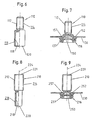
- Fig. 6 shows that it is not necessarily required that the head portion 116 of the functional element 110 has the same diameter as the shaft portion 114.
- the hollow head portion 116 has a larger diameter than the shaft portion 114.
- the Functional element 110 in the initial state does not have an actual flange. Rather, the flange is not formed until the functional element 110 has been introduced into a sheet-metal part, as described in connection with the first embodiment according to FIGS. 1 to 5 and shown in FIG.
- FIG. 7 now shows the functional element 110 of FIG. 6 in the installed state. It is readily apparent here that the annular fold 152 forms a flange, as in the embodiment according to FIG. 5.
- the head part 216 has a smaller outer diameter than the outer diameter of the threaded cylinder of the shank part 214 of the functional element 210.
- the functional element 210 initially lacks a flange which comes to rest on the sheet metal part , A flange is nevertheless formed during the introduction of the functional element into a sheet metal part by the compression of the hollow head part 216 to a ring fold or to a ring fold 252, as shown in FIG. 9 can be seen.
- Fig. 10 shows now that the functional element 310 can also be formed tubular.
- the functional element 310 of FIG. 10 is designed so that the shaft part 314 is also hollow.
- Such a functional element has the particular advantage that it can be readily manufactured from a tube profile, wherein the expansion of the bore B of the tube shown in Fig. 10 in the region of the cavity 318 can be readily made, for example, either when cold or at a High pressure forming process within a corresponding outer shape.
- the external thread 312 of the functional element 310 of FIG. 10 may be produced by a rolling process, as in the other previous examples, but may also be produced by a high pressure forming process within a mold.
- the positive connection of the head portion 316 corresponds to the sheet metal part of the previous embodiment of FIG .. 5
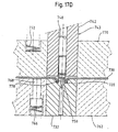
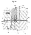
- Fig. 11 shows a further embodiment similar to the embodiment of FIG. 10, but here the element is provided with an internal thread 412.
- FIG. 12 shows the installed state of the functional element according to FIG. 11. It can be seen that the hollow head part 416 is deformed in the same way as in FIG the previous embodiments - with the difference that here the upper annular surface 457 of the annular rebate 452 is disposed slightly above the sheet metal part. But this is not mandatory. The corresponding surface could also be placed below the plane of the sheet metal part 430 or at the same height as the plane of the sheet metal part.
- the punched joint 450 closes the central passage of the hollow functional element 410 in the region of the rivet bead 437, so that a sealing takes place at this point. But the punching can also be removed.
- the embodiment according to FIG. 12 then has the particular advantage that a bolt element (not shown) can be screwed into the functional element 410 coming from below.
- a bolt element (not shown) can be screwed into the functional element 410 coming from below.
- the annular fold and the Nietbördel and the clamped therebetween material of the sheet metal part 430 when tightening the bolt even more firmly pulled together the large contact surface 480 of the annular fold forms a very stable connection.
- the stamping 450 is pressed, for example by means of a Vorlochst Zis in a central passage of the die and removed. The removal of such a Stanzbutzens in this way is known per se.
- the leading punch is used in such cases for pre-punching the sheet metal part.
- the die is then formed in a conventional manner so that it deforms only the free end of the hollow head part to the correspondingly deformed sheet metal part. That is, the die is formed with a center hole instead of a punch boss such as 34 in FIG.
- the slug may also be ejected in a subsequent operation when the element is inserted as shown in FIG.
- Fig. 13 shows a functional element 510, which is also tubular, but has no thread. Instead, the functional element has a circumferential groove 560 intended to receive a spring clip (not shown). It is also noted that the free end 529 of the functional element 510 of FIG. 13 is cone-shaped. The corresponding spring clip can be pressed down over this conical surface and then jumps into the groove 560 inside.
- the functional element 510 of FIG. 13 can be used in this or in a slightly modified form (for example, without a circumferential groove 560) in a sheet metal part and be used either as a pin or as a cylindrical pin. It could also be used with a thread-forming screw, which itself forms or cuts a thread when screwed into the finished assembly part in the hollow shaft part 514 of the functional element 510.
- the hollow head portion 316, 416, 516 may readily have a larger or smaller diameter than the outer diameter of the corresponding shaft portion 314, 414, 514.
- the inner punch 48 may optionally be guided into the hollow interior of the shaft part in order to stabilize the functional element during the upsetting process.
- This procedure which, moreover, advantageously influences the formation of the ring fold, is shown in FIG. 14, in the drawings 14B, 14C and 14D.
- the inner punch 648 has a pin-like projection 649 with a diameter corresponding to the inner diameter 651 of the hollow shaft part 614, wherein the projection 649 merges via an annular shoulder 653 in the upper part of the inner punch, which presses on the annular front end 629 of the shaft portion.
- the outer punch 642 of the punch assembly 643 shown in Figs. 14B to 14D may be provided with a circular cylindrical bore whose diameter corresponds to the diameter of the external thread 612 of the shaft member 614, approximately as shown in Figs. 14C and 14D.
- Fig. 14B indicates with the Doppfelpfeilen 655 for a possible remedy.
- the outer punch 642 is divided into at least two segments which can be moved radially away from the element 610 to the position 657 according to the Dopppfelpfeilen 655 in which they do not hinder the introduction of the element 610 through the punch channel 646 of the setting head ,
- These segments of which there may be two, three or more and which then have a corresponding angular extent (for example 180 °, 120 °, etc.), can be provided on their radially inner sides with a shape 659 matching the thread cylinder 612 so that upon a closing movement of the segments of the outer punch in the direction radially to the longitudinal axis 624 engage the thread segments of the corresponding thread 659 in the threads of the threaded cylinder 612 and thereby serve on the one hand the transmission of axial forces on the element 610 and on the other hand prevent a Compression or violation of the threaded cylinder 612 occurs.
- the figure is the Threaded segments 659 selected complementary to that of the threaded cylinder 612.
- the segments of the outer punch 642 are then moved apart again, i. in the direction radially outward away from the longitudinal axis 624, so that the outer punch 642 can be moved upwards to remove the finished assembly part according to FIG. 14E, without the threaded cylinder being damaged as a result.
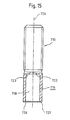
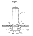
- FIG. 15 now shows a functional element 710 which is very similar to the functional element element 10 of FIG. 1 and basically differs therefrom only in that the bottom of the cavity 718 forming the transverse wall 722 is only slightly concave instead of cone-shaped is formed and extends substantially perpendicular to the longitudinal axis 724 of the element 710 and passes over a generous radius 723 in the cylindrical outer wall of the head portion 716 of the element 710.
- this form of bottom forming the transverse wall 722 is not absolutely necessary, in a practical example it leads to a high-quality support of the shaft part, which serves for the stability of the connection.
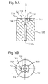
- FIGS. 16A and 16B show the die which is preferably used for inserting the functional element 710 of FIG. Although this die 732 is similar to the die of FIG. 2, it does have certain deviations.
- the stamp approach 734 is namely at this Embodiment in the direction of the longitudinal axis 724 extended axially upward, so that the flat end face 735 of the stamp projection 734 protrudes slightly above the end face 733 of the die.
- This design has the advantage that the functional element is still running with a cone-shaped cutting surface 726, but the end face 720 of the head part 716 is simply formed as an annular surface which is perpendicular to the longitudinal axis 724 and not rounded as for example at the rounding 28 in Fig. 1.
- the annular recess 740 of the die 732 is in principle similar to the annular recess 40 of the die 32 shown in FIG. 2 is formed, but is convex rounded at the transition to the end face 733, as shown at 737.
- a plurality of inclined grooves 739 are incorporated - in this embodiment, eight such grooves, as shown in Fig. 16B - so that radially extending lugs 741 are each formed between two adjacent grooves 739.
- the grooves 739 are at least substantially semicircular in cross section and well rounded as well as the intervening lugs 741, so that they deform the sheet metal part, but not hurt. These grooves 739 and lugs 741 serve to increase the security against rotation of the element with respect to the sheet metal part.
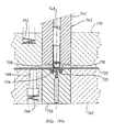
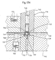
- FIGS. 17A to 17H now show the die 732 of FIG. 16 used to mount the functional element 710 in a sheet metal part 730 by means of a punch assembly 743.
- the die 732 is located here in a bore 760 of a lower tool 762 of a press, the upper side 764 is arranged flush with the end face 733 of the die.
- the lower tool 762 are several, with spring 766 upwardly biased plunger 768, which support the sheet metal part 730 upon insertion into the press, but due to the force exerted by a hold-down 770 force when pressing the press down, so that the Sheet metal part 730 comes to rest on the end face 733 of the die 732 and on the upper side 764 of the lower tool in the area of the die where it is immovably clamped between the hold-down 770 and the die 732 and the lower die 762.
- three such spring-biased plungers 768 can be provided, which are arranged, for example, at uniform angular intervals about the central longitudinal axis of the die 732, wherein only one plunger 768 can be seen due to the sectional drawing.
- the central longitudinal axis of the die is at the same time the central longitudinal axis 724 of the functional element 710, i. aligned with it.
- the hold-down 770 is also biased towards the sheet metal part 730 by springs 772, which are here - like the spring 776 - schematically indicated as a helical compression spring, although other types of springs come into question, which are well known in tooling.
- the holding-down device 770 may belong to a setting head having the stamp arrangement 743 or to a tool of the press on which the setting head is mounted.
- the spring 772 are accordingly supported at their upper ends on the set head or on the tool.
- three springs 772 are also arranged at regular angular intervals about the central longitudinal axis 724, so that the hold-down 770 is pressed down evenly under the force of these springs.
- Fig. 17A shows the state after the sheet metal part 730 has been inserted into the press and the closing movement of the press has begun, and just so far that the hold-down 770 rests on the top of the sheet metal part and the sheet metal part between them and the plunger 768 easily clamped.
- the punch arrangement 743 here too consists of an outer punch 742 and an inner punch 748, wherein the lower end face 774 of the inner punch 748 presses on the upper end face 729 of the functional element 710. It can be seen that the head part 716 of the functional element 710 protrudes at least substantially completely out of the outer punch 742, wherein the bottom wall 722 forming the bottom is arranged only slightly above the lower end face 776 of the outer punch 742. By contrast, the shaft part 714 of the functional element 712 is located completely inside the outer punch 742.
- the lower tool 762 represents the lower tool of a press, while the setting head is mounted in the upper tool of the press or on an intermediate plate. Also, other arrangements are conceivable, which have been described at the end of the description of FIG.
- the spring-biased hold-down 770 Upon further closing of the press, the spring-biased hold-down 770 is pressed so firmly against the sheet metal part 730 that this presses the spring-biased plunger 768 down until the sheet metal part 730 now firmly clamped between the hold-down 770 and the lower tool 762 and the end face 733 of Matrizeunver Wegbar.
- a further, downward movement of the blank holder 770 is not provided.
- the upper tool of the press or the intermediate plate of the press can according to the other. Closing movement of the press can be moved further down, whereby the compression coil spring 772 are further compressed without the hold-down 770 changes its position.
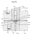
- the inner diameter of the shaft portion 716 i. It should also be noted that the lower end 720 of the functional element 710 under the pressure of the punch 748, the edge portion 778, which is the resulting by the severing of the punching 750 perforation of the Sheet metal part 730 has pressed into the ring depression 740 of the die 732, so that this edge region 778 forms a cone-shaped depression in the sheet metal part 730.
- the edge region 778 of the hole created by the cutting out of the punched casing 750 is pushed even further into the ring depression 736, wherein the front end 720 of the functional element 710 has just reached the U-shaped bottom region of the ring depression 736 and just is about to be deformed radially outward by the shape of this bottom portion.
- the region of the wall of the head part 16 of the functional element 10 below the kink point 782 is now formed into a ring fold or an annular bead 752.
- the end face 754 of the outer punch 742 now presses on the upper side of the sheet metal part 730.
- the stamp projection 756 has now flattened the upper side of the annular rebate 752, so that this surface is slight is arranged below the plane of the upper side of the sheet metal part 730 and is otherwise perpendicular to the longitudinal axis 724.
- the stamped joint 750 is now reached directly at the end of the cavity 718 of the head part 16 of the functional element 10 and supports the annular fold 752 from the inside.
- the press is now completely closed.
- the introduction of the functional element 710 in the sheet metal part 730 is now completed.
- the press now begins to open, as shown in Fig. 17H.
- the plunger 768 press the sheet metal part with attached functional element away from the lower tool 762 and lift the sheet metal part with the attached functional element from the die 732.
- the further opening movement of the press then causes the shaft part 714 of the functional element 710 to move away from the plunger 742 ,
- the sheet-metal part with the functional element attached thereto can now be removed from the press and appears as indicated in the illustration according to FIG. 17I.
- the inner punch 748 and the outer punch 742 move synchronously with one another.
- the inner punch 748 should still be movable upwards relative to the outer punch 742 in order to allow the insertion of the functional element 710 into the punch channel of the inner punch 742.
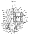
- FIG. 18 shows in detail a possible punch arrangement 842 which can be advantageously used instead of the punch arrangement 743 according to FIG. 17.
- the outer punch 842 is provided with an inner bore 886 which is coaxial with the longitudinal axis 824 'and slidably receives the inner punch 848.
- a supply passage 888 is shown, via which functional elements 810 can be guided by a feed device (not shown) into the stamp channel formed by the bore 886.
- the functional elements 810 shown in FIG. 18A approximately correspond to the shape of the functional elements 10 in accordance with FIG. 1, in which the bottom of the transverse wall is conical, come in principle all functional elements described so far in question, in front of all the functional elements 710 gem.
- the longitudinal axes 824 of the individual functional elements are parallel to the longitudinal axis 824 'of the punch channel 886 and that the individual functional elements are lined up in contact with one another. Due to the dimension of the punch channel 886, however, only one functional element 810 can be located in the punch channel 886.
- the outer punch 843 When the press is opened, the outer punch 843 is displaced downwardly relative to the inner punch 848, usually under the pressure of a corresponding spring, until the front end 874 of the inner punch 848 reaches approximately the height of the upper boundary of the feed passage 888, so that a Functional element 810 can be guided by pressure in the direction of arrow 890 in the punch channel 886.
- the outer punch 843 is formed in several parts in this embodiment and consists of a lower ring portion 892, which is fastened by means not shown screws on a top 894.
- the lower part 892 has a central opening 895 with a circular-cylindrical annular wall 896, which merges into a conical area 898. Both the circular cylindrical region 896 and the conical region 898 are arranged concentrically to the longitudinal axis 824 '.
- the upper part 894 of the outer punch 843 is a cone-shaped.
- Recess 900 provided, which merges via an annular shoulder 902 in the punch channel 886.
- the conical region 900 and the annular shoulder 902 are also arranged concentrically to the longitudinal axis 824 'of the stamp arrangement.
- the punch arrangement 842 there are in this example three segments 904 which are arranged at uniform angular intervals about the central longitudinal axis 824 '.
- the lower, radially inwardly directed surfaces 908 of the segments 904 are formed as a segment of a threaded cylinder, which is designed to be complementary to the threaded cylinder 812 of the shaft part 814 of the functional elements 810.
- the upper, radially inwardly directed surfaces 912 of the segments 904 together form a passage 913 with a diameter which is slightly smaller than the outer diameter of the head part 816 of the respective functional elements 810.
- the radially outer surfaces 914 of the segments 904 are designed as part-cone-shaped surfaces, which are complementary to the conical surface 900 of the corresponding recess of the upper part 894 of the outer punch 843.
- the radially upper surfaces 916 of the segments 904 are formed complementary to the annular shoulder 902, so that in the position shown in FIG. 18A the part-conical surfaces 914 of the segments 904 and the part-circular surfaces 916 rest against the respectively opposite surfaces of the outer punch 843, ie on the surface of the conical depression 900 and on the annular shoulder 902.
- the through-passage 913 which is formed by the segments 904, designed so that it is smaller in diameter than the outer diameter of the head part 16 of the functional element 810.
- the respective functional element 810 initially can not fall between the segments, but is supported at the upper end of the segments 904, as shown in Fig. 18A.
- the upper region of the respective segments 904 merges via a part-cone-shaped surface 920 into a part-cylindrical wall part 922.
- the part-cone-shaped surfaces 920 of the segments 904 are in the position shown in FIG. 18A of the cone-shaped surface 898 of the lower part 892 of the punch assembly 842 opposite to and have a distance therefrom.
- the part-cylindrical surfaces 922 of the segments 904 face the part-cylindrical surface 896 of the lower part 892 of the punch arrangement 843 and have a radial spacing therefrom.
- springs 926 have preloaded plungers 928 having their axes 930 oblique to longitudinal axis 824 'of plunger assembly 843 and perpendicular to conical surface 898 of base 892 of plunger assembly 843 stand. Due to the spring bias, the plungers 928 are pressed against the directly touching these part-conical surfaces 922 of the segments 904 so that they always assume the position shown in Fig. 18A with the press open.
- the spring preload is not very strong.
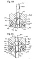
- the inner punch 848 is pressed downwards relative to the outer punch and thereby presses the respective functional element 810 located in the punch channel 886 against the upper end side of the segments 904. Due to the bevelled entrance to the passage 913 and the correspondingly inclined Outer surface in the region of the lower end face 820 of the respective functional element 810, the force exerted on the inner punch 848 is sufficient to press the segments downwardly in the axial direction 824 'and radially outwards, so that they push the pins 928 downward, until the part-cone-shaped surfaces 920 come into contact with the conical surface 898 of the lower part 892 of the outer punch 843.
- the arrangement is such that the inner punch 848 can not move down further than shown in Fig. 18C. This can be prevented, for example, by providing the upper part of the inner punch 848 with a head which, in the "lowest” position according to FIG. 18C, has come to bear against the outer part 842 of the punch.
- the entire force of the press is now on the inner punch 848 on the end face 829 of the functional element 810 and on the outer punch 842 and the segments 904 to the thread 812 of the functional element transferred. This ensures that the thread can not be damaged because it is positively received within the complementary threaded portions of the segments 904 and it is also ensured that the threaded cylinder can not be upset.
- the cylindrical projection 930 of the inner punch 848 can be designed accordingly and extend into the inner bore of the shaft part via an annular shoulder (not shown) pressing against the front end 829 of the functional element 810, so that the Pressing forces on the functional element 810 can be transmitted without damaging this element by compressing the wall of the hollow shaft part is to be feared, since this is supported by the extended projection of the inner punch.
- the number of segments 904 is not limited to three.
- the minimum number required to implement this embodiment is two, but three, four or more such elements may be used, preferably with a respective pin 928 with biasing spring 926 provided for each element.
- the lower ends of the segments 904 may, if desired, be provided with tabs 956 which together form the stamp projection 756 of FIG.
- the press opens again, the spring-loaded hold down a force on the sheet metal part with the attached Functional element which is sufficient to pull the segments 904 down to the position shown in FIG. 18B, to release the shaft portion 814. Since the spring tension of the spring 928 is small, the release of the functional element takes place at the opening of the press, without damaging the respective functional element 810 which has just been attached.
- the opening of the press causes the spring-biased outer punch 842 to be pushed downwardly while the inner punch 848 is pulled upward until it reaches the home position where the lower face of the mecanick Zis 848 has reached the height of the upper boundary of the passage 888, whereby a new element is guided into the punch channel 886 by the pressure in the direction of arrow 890.
- the working cycle then begins again with a new sheet metal part and with a new functional element 810, namely the functional element, which is now in the punch channel 886.
- the tool assembly may be a station of a progressive tool in which a metal strip is passed through a plurality of stations for performing a plurality of operations.
- the tool arrangement can also be used in a punch press, which performs only a single operation for each stroke.
- the attachment of the tool assembly to a robot or other type of tool is also possible.
- the functional elements of the present invention are not only intended for use with pure sheet metal parts, but can also be used with a number of other components that can be understood as composite components.
- Such components are often brittle or flexible components, which consist of a material containing cavities or pores and are often present as material composite material.
- brittle or flexible components which consist of a material containing cavities or pores and are often present as material composite material.
- material composite material such as a material containing cavities or pores.
- the following materials may be mentioned, which are used for the production of components, in particular brittle or resilient components, which can be equipped according to the invention with functional elements:
- metal foams offer material and weight savings and thus cost savings for a large number of components. They can absorb impact energy by progressive deformation and are therefore useful, for example, for energy absorbing parts, for example, for structural parts of vehicles that are to absorb impact energy to protect the occupants in accidents. In addition, they have excellent damping properties, so that they can absorb sound waves and mechanical vibrations well or weaken.
- Metal foams of aluminum and magnesium as well as metal foams of steel are known.
- Various manufacturing methods are known which can be used to produce such metal foams.
- metal powder may be mixed with a chemical compound that later foams upon thermal treatment of the metal. At the melting point of the metal gas is released, which leads to foaming. It has already succeeded in this way to produce aluminum foams, which have a gas content of up to 97%.
- steel foams can be produced by this method. The method is applicable to a wide range of elements and alloys. It is also possible to produce metal structures from hollow spheres, for example hollow steel spheres.
- magnesium foams with up to 60% gas content For the production of magnesium foams with up to 60% gas content is known to embed thin-walled ceramic hollow spheres in a casting process in a magnesium matrix, and also magnesium alloys are used and are freely selectable.
- such active ingredients may be stronger and more brittle or softer and more ductile than the starting alloy.
- foams After production of the foams, these are often provided with a cast skin, which are either removed or smoothed with a filler. Foams with a cast skin, possibly filled with a filling material, form a kind of sandwich structure.
- the metal foams described above can be produced with or without Gußhaut and provided with upper and / or lower cover layers or of sheet metal or plastic.
- any existing cover layers can be coated with all known coating methods, i. be provided with galvanic coatings, paint coatings or by means of PVD-applied coatings u.a.
- the sheet metal layers can be glued or bonded to the metal foam core, including soldering and brazing in question.
- adhesives are commonly used to achieve bonding to the core.
- Another method for producing sandwich structures is to provide hollow profiles made of metal or plastic, for example in the form of extrusion extruded profiles completely or partially with a metal foam core. This can be done by introducing elongated strips of metal foam, possibly with a surface bonding of the metal foam to the profile or by the foaming of metal / foam mixtures in the hollow profile.
- open profiles or molded sheet metal parts may be provided with a metal foam insert (insert of one layer of metal foam, or multiple layers of metal foam) and then covered with a cover strip or profile that is welded to the open profile edge portion , Riveting, gluing or otherwise fixing.
- metal foams plastic foams or other materials in such composite structures can be used.
- a concrete use of such, filled with metal foam or more fillers profiles represents the application as a B-pillar motor vehicle, the can be produced by the filling of a prefabricated profile, possibly with subsequent shaping by bending or pressing.
- the desired mechanical properties can be adjusted. For example, in one area the desired stiffness or buckling strength can be achieved, and in another area the desired deformation, for example in the case of an accident, can be achieved.
- honeycomb structure can be made of metal, of metal foils or of cardboard or paper or of plastic or of cellulose or lignocellulose.
- Such materials include i.a. Castings of e.g. Magnesium, magnesium alloys and thermosets with and without fillers. Such materials can also be used for components that are equipped according to the invention with functional element arrangements.
- plastic components components made of wood or chipboard or the like come for the assembly parts according to the invention in question, such materials are usually regarded as compliant, since They usually yield significantly at the forces that prevail in the production of a riveted joint.
- composite materials consist of a combination of one or more of the above-mentioned materials, for example multi-layer arrangements, which consist of several bonded together layers, whereby, for example, thicker components or components can be constructed with more complex shapes.
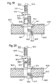
- FIGS. 19 and 20 show two possibilities how a functional element 1010 according to the invention with a composite component 1030 can be used.
- Fig. 19 shows the functional element 1010 in the initial state in a half-section on the left side of the central longitudinal axis 1024, wherein the other half of the functional element 1010 is formed symmetrically on the other side of the central longitudinal axis 1024, with the exception of the thread, of course with the shown Half of the thread forms a continuous threaded cylinder.
- a flange 1011 between the shaft portion 1014 and the head portion 1016 is provided and as shown here preferably carries lugs 1013, which serve as additional anti-rotation.
- the flange portion 1011 with the anti-rotation features 1013 may be omitted if desired, but provides for a more stable attachment of the functional element 1010 to the composite component 1030.
- the composite component 1030 may have any of the configurations noted above for composite components.
- the composite component Prior to attachment of the functional element, the composite component is prepared as shown on the left side of the central longitudinal axis 1024.
- a cylindrical bore 1031 with a circular cylindrical wall was produced in the component 1030 and that the upper layer 1033 of the composite component 1030 was formed into a bead-shaped depression 1035.
- the bore 1031 can be made by a boring process or by a stamping operation, while the bead 1035 is usually made by a stamping step, for example in a stamping press. If both the bore 1031 and the bead 1035 are produced by punching, this can be done in one step by means of a correspondingly shaped punching tool.
- the bead 1035 has a shape similar to that of the flange portion 1011.
- the shape of the Fig. 5th is very similar, in the sense that the hollow head portion 1016 is formed in the region of its front end to a Nietbördel 1037, which comes to lie below the lower layer 1039 of the composite component 1030 and that the area of the hollow head portion 1016 above this lower layer 1039 to a ring rebate 1052 is formed, which forms a U-shaped annular groove with the Nietbördel 1037, in which the edge region of the lower layer 1039, which was previously the hole 1031 defined, was taken. It is also noted, however, that the annular rebate 1052 is not quite as pronounced as the annular flange 52 in the Fig. 5 embodiment, which is understandable, since it is not possible in this embodiment to burden this area with an outer punch.
- a punched slug is missing, since the composite component 1030 is predrilled here.
- the lower end of the functional element 1010 shown in FIG. 19 is not pushed through the lower layer 1039 in a self-piercing manner. Since no punching slug is formed here, it is not necessary to make the rounded ring recess or rolling surface of the die as deep as shown at 36 in FIG.
- the anti-rotation locking lugs and features 1013 are pressed into the top of the upper layer of the composite member 1030 in the region of the bead 1035 , After attachment of the functional element, the upper side 1041 of the flange part 1011 is approximately flush with the upper side of the upper layer 1033 of the composite component 1030 in FIG. 19.
- the core material of the composite component 1030 is corresponding in the region of the annular rebate 1052 and the U-shaped annular groove 1053 deformed the course of the Ringfalzes and the lower layer 1039.
- a flange portion 1011 is not provided, a bead 1035 is unnecessary and the prepared component 1030 then has only a cylindrical bore, wherein the circular opening in the upper layer should preferably have at least substantially the same diameter as the outer diameter of the hollow head portion 1016th
- FIG. 20 shows a slightly modified embodiment in comparison to FIG. 19.
- the component 1030 is also prepared by producing a cylindrical bore 1031, this bore 1031, however, stops immediately above the lower layer 1039 of the composite component 1030 on. Also, no bead 1035 is produced in the upper layer 1033 of the composite component 1030 here.
- the diameter of the bore 1031 corresponds, as in the embodiment of FIG. 19, at least substantially the outer diameter of the hollow head portion 1016 of the functional element 1010, which is identical here with the corresponding element 1010 of FIG. 19.
- the lower end face of the functional element 1010 is provided with punching features which, in cooperation with a corresponding die (approximately corresponding to the die of Fig. 2), results in the blanking of a blanking die 1050, due to a higher positioned center post of the die this punching slug is pressed into this hollow head part 1016 in the region of the transverse wall 1022 of the hollow head part 1016.
- the underside of the flange part 1011 of the functional element rests on the upper side of the upper layer 1033. This is only slightly pressed, especially in the area of anti-rotation lug features 1013, just to produce the required anti-rotation.
- the composite member 1030 is under some compression between the flange portion 1011 and the rivet crimp 1037, which adds to the quality and stability of the connection.
- the functional elements described here can be made, for example, from all materials that reach the strength class 5.6.
- Such metal materials are usually carbon steels with 0.15 to 0.55% carbon content.
- the material of the functional elements all materials can be mentioned, which reach the strength values of Class 8 according to Isostandard in the context of cold working, for example, a 35B2 alloy according to DIN 1654.
- the fasteners thus formed are u.a.
- steel materials for drawable sheet metal parts as well as for aluminum or their alloys.
- aluminum alloys, especially those with high strength, can be used for the functional elements, e.g. AlMg5.
- the ratio of the radial wall thickness of the head part to the outside diameter of the head part is in the range between 0.15 to 0.2. Higher values can be achieved since they increase the breaking forces or extraction forces. However, it must be ensured that the pressing forces do not stir to an impermissible deformation. With a diameter of 8 mm, a radial wall thickness of 1.2 mm has proved favorable.
Landscapes
- Engineering & Computer Science (AREA)
- General Engineering & Computer Science (AREA)
- Mechanical Engineering (AREA)
- Insertion Pins And Rivets (AREA)
- Connection Of Plates (AREA)
- Automatic Assembly (AREA)
- Refuge Islands, Traffic Blockers, Or Guard Fence (AREA)
- Perforating, Stamping-Out Or Severing By Means Other Than Cutting (AREA)
- Moulds, Cores, Or Mandrels (AREA)
Applications Claiming Priority (7)
| Application Number | Priority Date | Filing Date | Title |
|---|---|---|---|
| DE19932023 | 1999-07-09 | ||
| DE19932023 | 1999-07-09 | ||
| DE19935923 | 1999-07-30 | ||
| DE19935923 | 1999-07-30 | ||
| DE10018716 | 2000-04-16 | ||
| DE10018716 | 2000-04-16 | ||
| EP00947949A EP1202834B1 (de) | 1999-07-09 | 2000-07-07 | Funktionselement, verfahren zum einbringen des funktionselementes in ein blechteil, zusammenbauteil |
Related Parent Applications (1)
| Application Number | Title | Priority Date | Filing Date |
|---|---|---|---|
| EP00947949A Division EP1202834B1 (de) | 1999-07-09 | 2000-07-07 | Funktionselement, verfahren zum einbringen des funktionselementes in ein blechteil, zusammenbauteil |
Publications (3)
| Publication Number | Publication Date |
|---|---|
| EP1249305A2 EP1249305A2 (de) | 2002-10-16 |
| EP1249305A3 EP1249305A3 (de) | 2003-01-15 |
| EP1249305B1 true EP1249305B1 (de) | 2007-01-17 |
Family
ID=27213801
Family Applications (2)
| Application Number | Title | Priority Date | Filing Date |
|---|---|---|---|
| EP02012625A Expired - Lifetime EP1249305B1 (de) | 1999-07-09 | 2000-07-07 | Stempelanordnung |
| EP00947949A Expired - Lifetime EP1202834B1 (de) | 1999-07-09 | 2000-07-07 | Funktionselement, verfahren zum einbringen des funktionselementes in ein blechteil, zusammenbauteil |
Family Applications After (1)
| Application Number | Title | Priority Date | Filing Date |
|---|---|---|---|
| EP00947949A Expired - Lifetime EP1202834B1 (de) | 1999-07-09 | 2000-07-07 | Funktionselement, verfahren zum einbringen des funktionselementes in ein blechteil, zusammenbauteil |
Country Status (11)
| Country | Link |
|---|---|
| US (1) | US7131807B1 (enExample) |
| EP (2) | EP1249305B1 (enExample) |
| JP (1) | JP4679777B2 (enExample) |
| KR (1) | KR100637791B1 (enExample) |
| AU (1) | AU6156600A (enExample) |
| BR (1) | BR0012334B1 (enExample) |
| CA (1) | CA2378812C (enExample) |
| DE (3) | DE10033149A1 (enExample) |
| ES (2) | ES2275779T3 (enExample) |
| MX (1) | MXPA02000041A (enExample) |
| WO (1) | WO2001003880A1 (enExample) |
Families Citing this family (24)
| Publication number | Priority date | Publication date | Assignee | Title |
|---|---|---|---|---|
| AU6156600A (en) * | 1999-07-09 | 2001-01-30 | Profil Verbindungstechnik Gmbh & Co. Kg | Functional element, method for fixing it in a sheet metal part, assembling element and swaging assembly |
| US7731467B2 (en) | 1999-07-09 | 2010-06-08 | Profil Verbindungstechnik Gmbh & Co., Kg | Bolt element having a shaft part and a spherical head, component assembly and method for the manufacture of a bolt element |
| DE10015239A1 (de) * | 2000-03-27 | 2001-10-04 | Profil Verbindungstechnik Gmbh | Funktionselementanordnung, Funktionselement, Hilfsfügeteil, Zusammenbauteil und Verfahren zur Herstellung eines Zusammenbauteils |
| JP2001343010A (ja) * | 2000-06-01 | 2001-12-14 | Shinjo Seisakusho:Kk | 打込みボルト及び該打込みボルトの組立体 |
| DE50105567D1 (de) | 2000-12-29 | 2005-04-14 | Profil Verbindungstechnik Gmbh | Bolzenelement mit einem Schaftteil und einem Kugelkopf, Zusammenbauteil und Verfahren zur Herstellung eines solchen Bolzenelements |
| DE10114200A1 (de) | 2001-03-23 | 2002-09-26 | Profil Verbindungstechnik Gmbh | Funktionselement, Zusammenbauteil bestehend aus einem Blechteil und einem Funktionselement sowie Verfahren zur Anbringung eines Funktionselementes an ein Blechteil |
| DE10243759B4 (de) | 2002-09-20 | 2011-08-11 | PROFIL Verbindungstechnik GmbH & Co. KG, 61381 | Verfahren zur Erzeugung einer elektrisch leitenden Verbindung zwischen einer elektrischen Anschlusseinrichtung wie ein Kabelschuh und einem Blechteil, Befestigungselement und Zusammenbauteil |
| DE20106003U1 (de) | 2001-04-05 | 2001-09-27 | Norsk Hydro Asa, Oslo | Haltevorrichtung |
| DE10117060A1 (de) * | 2001-04-05 | 2002-10-10 | Profil Verbindungstechnik Gmbh | Verfahren zum Anbringen eines Funktionselements an ein Bauteil sowie dazugehöriges Werkzeug |
| DE10118149A1 (de) * | 2001-04-11 | 2002-10-17 | Profil Verbindungstechnik Gmbh | Verfahren zum Anbringen eines Funktionselements an ein Bauteil sowie dazugehöriges Werkzeug |
| US6791051B2 (en) * | 2002-08-22 | 2004-09-14 | Delphi Technologies, Inc. | Method for metallurgically attaching a tube to a member |
| DE102004043688A1 (de) * | 2004-06-23 | 2006-04-06 | Profil-Verbindungstechnik Gmbh & Co. Kg | Verfahren zur Herstellung eines Zusammenbauteils bestehend aus einem Blechteil und einem an diesem angebrachten Funktionselement, Blechteil sowie Funktionselement |
| DE102004030223A1 (de) * | 2004-06-23 | 2006-01-12 | Profil Verbindungstechnik Gmbh & Co. Kg | Verfahren zur Herstellung eines Zusammenbauteils bestehend aus einem Blechteil und einem an diesem angebrachten Funktionselement, Blechteil sowie Funktionselement |
| KR100696537B1 (ko) * | 2005-10-05 | 2007-03-19 | 삼성에스디아이 주식회사 | 섀시 보스 조립체 및 이를 구비하는 디스플레이 장치 |
| US8328489B2 (en) * | 2007-12-17 | 2012-12-11 | Acument Intellectual Properties, Llc | Self-pierce rivets and an adjustable strap handle |
| DE102009037427A1 (de) | 2009-08-13 | 2011-02-17 | Profil Verbindungstechnik Gmbh & Co. Kg | Funktionselement, Verfahren zum Einbringen des Funktionselementes in ein Blechteil sowie Zusammenbauteil |
| KR101214011B1 (ko) | 2010-05-31 | 2012-12-26 | 로베르트 보쉬 게엠베하 | 전극 단자 구조 및 이를 이용한 이차 전지 |
| DE102011051137B4 (de) | 2011-06-17 | 2023-01-19 | Dr. Ing. H.C. F. Porsche Aktiengesellschaft | Aufbaustruktur eines Kraftfahrzeugs mit einem Blechteil und einem Befestigungselement |
| DE102012008798B4 (de) * | 2012-03-31 | 2016-01-14 | Johnson Controls Gmbh | Verfahren zum Fügen sowie Verbindungselement |
| DE102012215263A1 (de) * | 2012-08-28 | 2014-03-06 | BSH Bosch und Siemens Hausgeräte GmbH | Gargerät |
| CN105065406B (zh) * | 2015-08-07 | 2017-12-12 | 珠海格力电器股份有限公司 | 铆接结构、铆接模具、铆接工艺及空调 |
| US9701227B2 (en) * | 2015-10-08 | 2017-07-11 | Brose Fahrzeugteile Gmbh & Co. Kommanditgesellschaft | Assembly group of a vehicle seat comprising a tube element and an attachment part arranged thereon |
| TWI714898B (zh) * | 2018-11-01 | 2021-01-01 | 達霆精密工業有限公司 | 操控裝置 |
| CN116487789A (zh) * | 2022-01-13 | 2023-07-25 | 宁德时代新能源科技股份有限公司 | 箱体、电池、用电装置以及制备电池的方法和装置 |
Family Cites Families (27)
| Publication number | Priority date | Publication date | Assignee | Title |
|---|---|---|---|---|
| US2071507A (en) * | 1935-04-29 | 1937-02-23 | Scovill Manufacturing Co | Method of applying fasteners to sheet like material |
| GB1205744A (en) | 1966-10-12 | 1970-09-16 | Linread Ltd | Improvements in or relating to tubular fasteners |
| US3624867A (en) * | 1968-09-20 | 1971-12-07 | Amp Inc | Plastic locking nut in strip form |
| GB1341654A (en) * | 1972-03-02 | 1973-12-25 | Playart Ltd | Battery powered toys or models |
| US4039099A (en) * | 1976-02-11 | 1977-08-02 | National Can Corporation | Securing of rivets to portable articles |
| US4204308A (en) * | 1978-08-01 | 1980-05-27 | Marling Douglas S | Screw extracting device |
| IL58535A0 (en) * | 1979-10-23 | 1980-01-31 | Danino A | A blind nut and drive head for its mounting |
| US4555838A (en) * | 1983-03-28 | 1985-12-03 | Multifastener Corp. | Method of installing self-attaching fasteners |
| US4633560A (en) * | 1980-02-02 | 1987-01-06 | Multifastener Corporation | Self-attaching fastener, die set |
| US4430034A (en) * | 1981-07-07 | 1984-02-07 | Fukui Byora Co. | Stud bolt for metal panels |
| US4826372A (en) * | 1986-08-06 | 1989-05-02 | Victor Pastushin | Pre-locked pull-type blind fastener |
| US5140735A (en) * | 1990-01-16 | 1992-08-25 | Multifastener Corporation | Die member for attaching a self-piercing and riveting fastener |
| US5528812A (en) * | 1991-10-31 | 1996-06-25 | Profil-Verbindungstechnik Gmbh & Co. Kg | Method of attaching a fastener to a plurality of panels |
| DE4211276C2 (de) * | 1992-04-03 | 1997-08-28 | Profil Verbindungstechnik Gmbh | Haltevorrichtung zum Halten, Führen und Freigeben eines Fügeteils, wie z.B. einer Mutter |
| NO931702D0 (no) * | 1993-05-10 | 1993-05-10 | Svein Ove Johnsen | Selvborende blindnagle samt anordning for bruk ved blindnagling |
| WO1995027147A1 (en) * | 1994-04-04 | 1995-10-12 | Textron Inc. | Staked fastener with undercut |
| DE4447620C2 (de) * | 1994-06-10 | 2003-01-23 | Profil Verbindungstechnik Gmbh | Haltefinger und Setzkopf mit mehreren solchen Haltefingern |
| DE29509439U1 (de) * | 1995-06-09 | 1995-08-24 | Böllhoff GmbH Verbindungs- und Montagetechnik, 33649 Bielefeld | Stanzniet, insbesondere mit einem am Nietkopf angeformten Gewindebolzen |
| US6257814B1 (en) * | 1995-08-18 | 2001-07-10 | Profil Verbindungstechnik & Co. | Self-attaching fastener, method of forming same and method of attachment |
| DE19647831A1 (de) * | 1996-11-19 | 1998-05-20 | Profil Verbindungstechnik Gmbh | Verfahren zur Anbringung eines Funktionselementes; Funktionselement, Zusammenbauteil, Matrize und Setzkopf |
| DE19701780A1 (de) * | 1997-01-20 | 1998-07-23 | Emhart Inc | Stanzniet und mit ihm erstellte Nietverbindungen sowie Nietwerkzeug und Verfahrensherstellung einer Nietverbindung |
| DE19732517A1 (de) * | 1997-07-29 | 1999-02-04 | Bergner Richard Gmbh Co | Verfahren zur Erzeugung eines bündigen Dornbruches auf Setzkopfhöhe an Dornbruchblindnieten mit verbleibenden Restdorn |
| US6325584B1 (en) * | 1999-03-30 | 2001-12-04 | Richard Bergner Gmbh | Self-piercing rivet |
| US6332261B1 (en) * | 1999-06-30 | 2001-12-25 | Dura Convertible Systems Gmbh | Process for the attachment of a mounting rail as well as a connecting device for a mounting rail |
| AU6156600A (en) * | 1999-07-09 | 2001-01-30 | Profil Verbindungstechnik Gmbh & Co. Kg | Functional element, method for fixing it in a sheet metal part, assembling element and swaging assembly |
| US6213699B1 (en) * | 1999-09-10 | 2001-04-10 | Huck International, Inc. | Filling rivet with high pin lock |
| US20030123947A1 (en) * | 2001-12-27 | 2003-07-03 | Soheil Eshraghi | Blind rivet with hollow head |
-
2000
- 2000-07-07 AU AU61566/00A patent/AU6156600A/en not_active Abandoned
- 2000-07-07 DE DE10033149A patent/DE10033149A1/de not_active Withdrawn
- 2000-07-07 MX MXPA02000041A patent/MXPA02000041A/es active IP Right Grant
- 2000-07-07 DE DE50013986T patent/DE50013986D1/de not_active Expired - Lifetime
- 2000-07-07 ES ES02012625T patent/ES2275779T3/es not_active Expired - Lifetime
- 2000-07-07 JP JP2001509339A patent/JP4679777B2/ja not_active Expired - Fee Related
- 2000-07-07 BR BRPI0012334-0A patent/BR0012334B1/pt not_active IP Right Cessation
- 2000-07-07 EP EP02012625A patent/EP1249305B1/de not_active Expired - Lifetime
- 2000-07-07 CA CA002378812A patent/CA2378812C/en not_active Expired - Fee Related
- 2000-07-07 KR KR1020027000344A patent/KR100637791B1/ko not_active Expired - Fee Related
- 2000-07-07 WO PCT/EP2000/006465 patent/WO2001003880A1/de not_active Ceased
- 2000-07-07 US US10/030,410 patent/US7131807B1/en not_active Expired - Fee Related
- 2000-07-07 EP EP00947949A patent/EP1202834B1/de not_active Expired - Lifetime
- 2000-07-07 DE DE50000985T patent/DE50000985D1/de not_active Expired - Lifetime
- 2000-07-07 ES ES00947949T patent/ES2184718T3/es not_active Expired - Lifetime
Also Published As
| Publication number | Publication date |
|---|---|
| KR100637791B1 (ko) | 2006-10-23 |
| BR0012334B1 (pt) | 2009-01-13 |
| BR0012334A (pt) | 2002-03-19 |
| ES2184718T3 (es) | 2003-04-16 |
| KR20020037743A (ko) | 2002-05-22 |
| CA2378812A1 (en) | 2001-01-18 |
| EP1202834A1 (de) | 2002-05-08 |
| EP1202834B1 (de) | 2002-12-18 |
| DE50000985D1 (de) | 2003-01-30 |
| DE10033149A1 (de) | 2001-02-01 |
| AU6156600A (en) | 2001-01-30 |
| EP1249305A2 (de) | 2002-10-16 |
| JP2003504568A (ja) | 2003-02-04 |
| EP1249305A3 (de) | 2003-01-15 |
| MXPA02000041A (es) | 2002-07-02 |
| US7131807B1 (en) | 2006-11-07 |
| ES2275779T3 (es) | 2007-06-16 |
| CA2378812C (en) | 2009-03-10 |
| JP4679777B2 (ja) | 2011-04-27 |
| WO2001003880A1 (de) | 2001-01-18 |
| DE50013986D1 (de) | 2007-03-08 |
Similar Documents
| Publication | Publication Date | Title |
|---|---|---|
| EP1249305B1 (de) | Stempelanordnung | |
| EP1269033B1 (de) | Funktionselementanordnung, funktionselement, hilfsfügeteil, zusammenbauteil und verfahren zur herstellung eines zusammenbauteils | |
| EP2177776B1 (de) | Vorrichtung bestehend aus einem Befestigunselement und einem Blechteil sowie ein Verfahren zur Herstellung einer solchen Vorrichtung | |
| EP0993902B1 (de) | Verfahren zur Anbringung eines Funktionselementes, Matrize, Funktionselement, Zusammenbauteil | |
| EP2980426B1 (de) | Zusammenbauteil bestehend aus einem einpresselement und einem blechteil | |
| EP2283965B1 (de) | Funktionselement, Verfahren zum Einbringen des Funktionselementes in ein Blechteil sowie Zusammenbauteil | |
| EP1068458A1 (de) | Verbindungseinrichtung zum verbinden zweier bauteile, kombination der verbindungseinrichtung mit den beiden bauteilen und verfahren zur herstellung einer verbindung zwischen zwei bauteilen | |
| EP0758039A1 (de) | Ankerschiene für die Bautechnik | |
| DE3446978A1 (de) | Verfahren und vorrichtung zum befestigen eines hohlkoerperteils an einer tafel | |
| EP1068457A2 (de) | Verfahren, werkzeug und stempel zum verbinden von bauteilen mit einer platte | |
| EP0842733A2 (de) | Verfahren zur Anbringung eines Funktionselementes, Funktionselement, Zusammenbauteil, Matrize und Setzkopf | |
| DE102013217640A1 (de) | Verfahren zur Anbringung eines Befestigungselements an ein Werkstück, Kombination einer Scheibe mit einer Matrize sowie Matrize | |
| EP1690013A1 (de) | Funktionselement, zusammenbauteil bestehend aus dem funktionselement in kombination mit einem blechteil, verfahren zur herstellung des zusammenbauteils sowie verfahren zur herstellung des funktionselements | |
| EP1442809B1 (de) | Verfahren zur Herstellung von Hohlkörperelementen | |
| EP1346160B1 (de) | Bolzenelement mit einem Schaftteil und einem Kugelkopf, Zusammenbauteil und Verfahren zur Herstellung eines solchen Bolzenelements | |
| EP1194264B1 (de) | Verfahren zur anbringung eines funktionselementes; matrize; funktionselement; zusammenbauteil und stempelanordnung | |
| DE4404659A1 (de) | Verfahren zum Herstellen einer Nietverbindung | |
| DE102008053346A1 (de) | Abstandselement für die Anbringung an einem Blechteil, Zusammenbauteil und Verfahren zu dessen Herstellung | |
| DE102008023044B4 (de) | Verfahren zum Anbringen eines Füge- oder Funktionselementes an einem plastisch verformbaren Flachmaterial | |
| EP1379790A1 (de) | Verfahren zur herstellung eines zusammenbauteils bestehend aus einem blechteil und einem gewindestift sowie zusammenbauteil. |
Legal Events
| Date | Code | Title | Description |
|---|---|---|---|
| PUAI | Public reference made under article 153(3) epc to a published international application that has entered the european phase |
Free format text: ORIGINAL CODE: 0009012 |
|
| 17P | Request for examination filed |
Effective date: 20020606 |
|
| AC | Divisional application: reference to earlier application |
Ref document number: 1202834 Country of ref document: EP |
|
| AK | Designated contracting states |
Kind code of ref document: A2 Designated state(s): DE ES FR GB IT SE |
|
| PUAL | Search report despatched |
Free format text: ORIGINAL CODE: 0009013 |
|
| AK | Designated contracting states |
Kind code of ref document: A3 Designated state(s): DE ES FR GB IT SE |
|
| AKX | Designation fees paid |
Designated state(s): DE ES FR GB IT SE |
|
| 17Q | First examination report despatched |
Effective date: 20041012 |
|
| GRAP | Despatch of communication of intention to grant a patent |
Free format text: ORIGINAL CODE: EPIDOSNIGR1 |
|
| 17Q | First examination report despatched |
Effective date: 20041012 |
|
| GRAS | Grant fee paid |
Free format text: ORIGINAL CODE: EPIDOSNIGR3 |
|
| GRAA | (expected) grant |
Free format text: ORIGINAL CODE: 0009210 |
|
| AC | Divisional application: reference to earlier application |
Ref document number: 1202834 Country of ref document: EP Kind code of ref document: P |
|
| AK | Designated contracting states |
Kind code of ref document: B1 Designated state(s): DE ES FR GB IT SE |
|
| REG | Reference to a national code |
Ref country code: GB Ref legal event code: FG4D Free format text: NOT ENGLISH |
|
| REF | Corresponds to: |
Ref document number: 50013986 Country of ref document: DE Date of ref document: 20070308 Kind code of ref document: P |
|
| REG | Reference to a national code |
Ref country code: SE Ref legal event code: TRGR |
|
| RAP2 | Party data changed (patent owner data changed or rights of a patent transferred) |
Owner name: PROFIL VERBINDUNGSTECHNIK GMBH & CO. KG |
|
| GBT | Gb: translation of ep patent filed (gb section 77(6)(a)/1977) |
Effective date: 20070418 |
|
| REG | Reference to a national code |
Ref country code: GB Ref legal event code: 732E |
|
| REG | Reference to a national code |
Ref country code: ES Ref legal event code: FG2A Ref document number: 2275779 Country of ref document: ES Kind code of ref document: T3 |
|
| ET | Fr: translation filed | ||
| PLBE | No opposition filed within time limit |
Free format text: ORIGINAL CODE: 0009261 |
|
| STAA | Information on the status of an ep patent application or granted ep patent |
Free format text: STATUS: NO OPPOSITION FILED WITHIN TIME LIMIT |
|
| 26N | No opposition filed |
Effective date: 20071018 |
|
| REG | Reference to a national code |
Ref country code: GB Ref legal event code: 732E |
|
| REG | Reference to a national code |
Ref country code: FR Ref legal event code: CD Ref country code: FR Ref legal event code: CA Ref country code: FR Ref legal event code: TP |
|
| REG | Reference to a national code |
Ref country code: FR Ref legal event code: GC |
|
| REG | Reference to a national code |
Ref country code: FR Ref legal event code: GC |
|
| REG | Reference to a national code |
Ref country code: FR Ref legal event code: RG Effective date: 20150206 |
|
| REG | Reference to a national code |
Ref country code: FR Ref legal event code: PLFP Year of fee payment: 16 |
|
| PGFP | Annual fee paid to national office [announced via postgrant information from national office to epo] |
Ref country code: FR Payment date: 20150626 Year of fee payment: 16 |
|
| PGFP | Annual fee paid to national office [announced via postgrant information from national office to epo] |
Ref country code: ES Payment date: 20150728 Year of fee payment: 16 Ref country code: GB Payment date: 20150721 Year of fee payment: 16 |
|
| PGFP | Annual fee paid to national office [announced via postgrant information from national office to epo] |
Ref country code: SE Payment date: 20150721 Year of fee payment: 16 |
|
| PGFP | Annual fee paid to national office [announced via postgrant information from national office to epo] |
Ref country code: IT Payment date: 20150727 Year of fee payment: 16 |
|
| REG | Reference to a national code |
Ref country code: SE Ref legal event code: EUG |
|
| GBPC | Gb: european patent ceased through non-payment of renewal fee |
Effective date: 20160707 |
|
| PG25 | Lapsed in a contracting state [announced via postgrant information from national office to epo] |
Ref country code: FR Free format text: LAPSE BECAUSE OF NON-PAYMENT OF DUE FEES Effective date: 20160801 Ref country code: SE Free format text: LAPSE BECAUSE OF NON-PAYMENT OF DUE FEES Effective date: 20160708 |
|
| REG | Reference to a national code |
Ref country code: FR Ref legal event code: ST Effective date: 20170331 |
|
| PG25 | Lapsed in a contracting state [announced via postgrant information from national office to epo] |
Ref country code: GB Free format text: LAPSE BECAUSE OF NON-PAYMENT OF DUE FEES Effective date: 20160707 |
|
| PG25 | Lapsed in a contracting state [announced via postgrant information from national office to epo] |
Ref country code: IT Free format text: LAPSE BECAUSE OF NON-PAYMENT OF DUE FEES Effective date: 20160707 |
|
| PG25 | Lapsed in a contracting state [announced via postgrant information from national office to epo] |
Ref country code: ES Free format text: LAPSE BECAUSE OF NON-PAYMENT OF DUE FEES Effective date: 20160708 |
|
| PGFP | Annual fee paid to national office [announced via postgrant information from national office to epo] |
Ref country code: DE Payment date: 20190927 Year of fee payment: 20 |
|
| REG | Reference to a national code |
Ref country code: DE Ref legal event code: R071 Ref document number: 50013986 Country of ref document: DE |