EP1249296A2 - Procédé et appareil de soudage de tubes ensemble - Google Patents
Procédé et appareil de soudage de tubes ensemble Download PDFInfo
- Publication number
- EP1249296A2 EP1249296A2 EP02013572A EP02013572A EP1249296A2 EP 1249296 A2 EP1249296 A2 EP 1249296A2 EP 02013572 A EP02013572 A EP 02013572A EP 02013572 A EP02013572 A EP 02013572A EP 1249296 A2 EP1249296 A2 EP 1249296A2
- Authority
- EP
- European Patent Office
- Prior art keywords
- welding
- pipeline
- equipment holder
- pipe section
- rotary equipment
- Prior art date
- Legal status (The legal status is an assumption and is not a legal conclusion. Google has not performed a legal analysis and makes no representation as to the accuracy of the status listed.)
- Withdrawn
Links
Images


Classifications
-
- B—PERFORMING OPERATIONS; TRANSPORTING
- B23—MACHINE TOOLS; METAL-WORKING NOT OTHERWISE PROVIDED FOR
- B23K—SOLDERING OR UNSOLDERING; WELDING; CLADDING OR PLATING BY SOLDERING OR WELDING; CUTTING BY APPLYING HEAT LOCALLY, e.g. FLAME CUTTING; WORKING BY LASER BEAM
- B23K9/00—Arc welding or cutting
- B23K9/02—Seam welding; Backing means; Inserts
- B23K9/028—Seam welding; Backing means; Inserts for curved planar seams
- B23K9/0282—Seam welding; Backing means; Inserts for curved planar seams for welding tube sections
- B23K9/0286—Seam welding; Backing means; Inserts for curved planar seams for welding tube sections with an electrode moving around the fixed tube during the welding operation
-
- B—PERFORMING OPERATIONS; TRANSPORTING
- B23—MACHINE TOOLS; METAL-WORKING NOT OTHERWISE PROVIDED FOR
- B23K—SOLDERING OR UNSOLDERING; WELDING; CLADDING OR PLATING BY SOLDERING OR WELDING; CUTTING BY APPLYING HEAT LOCALLY, e.g. FLAME CUTTING; WORKING BY LASER BEAM
- B23K2101/00—Articles made by soldering, welding or cutting
- B23K2101/04—Tubular or hollow articles
- B23K2101/10—Pipe-lines
Definitions
- the present invention relates to an apparatus and method for welding pipes together. More specifically the invention relates to arc-welding together pipe sections when laying pipelines underwater, especially at sea.
- the pipe sections may consist of a plurality of pipe lengths each welded together on the lay-barge to form the pipe sections when required.
- the radial distance of the electrode with respect to the pipes must change in relation to the depth of the weld joint. As the region of the joint between the pipes is filled with welded metal the surface of the welded metal gets closer to the welding torch.
- a known method of welding two pipes together may be described as follows.
- the pipes to be joined are prepared prior to the welding process by bevelling the ends of the pipes such that when the pipes are arranged immediately before the welding process commences (coaxially with respect to each other), an exterior circumferential groove is defined between the two pipes.
- the pipes are positioned ready for welding.
- a carriage is mounted on one of the pipes for movement around the circumference of the pipes to be joined.
- a welding torch is mounted on the carriage and the apparatus is so arranged that the end of the metal electrode of the torch is opposite and relatively close to the circumferential groove. The carriage is moved around the circumference of the pipe and the torch is operated so that an arc is directed into the groove.
- the arc is guided manually and/or by various mechanical sensors to guide the arc as accurately as possible along the length of the groove.
- the welding process generally takes several passes.
- the resolution of the mechanical sensors is such that a human operator is required to assist in the welding process for guiding the arc with sufficient accuracy.
- An object of the present invention is to provide an apparatus and method for welding pipes together that mitigates at least some of the above-mentioned disadvantages associated with the known method and apparatus described above.
- a further object of the present invention is to provide an apparatus and method for welding pipes together that is faster at welding pipes together than the known method and apparatus described above but without significantly reducing the quality of weld joint.
- a J-lay apparatus as set forth in claim 1 of the accompanying claims.
- Optional features of this aspect of the invention are set forth in claims 2 to 15.
- the first aspect of the invention also provides a rotary equipment holder as set forth in claims 16 and 17, a welding assembly as set forth in claims 18 to 20 and a method of J-laying a pipeline as set forth in claims 21 to 25.
- an apparatus for a pipe-laying vessel comprising a rotary table mounted for rotation about a generally vertical axis and having a central opening through which pipe sections each having a pipe axis are able to pass as a pipeline is laid.
- the rotary table may be mounted on a frame which is fixed to the pipe-laying vessel.
- the apparatus may further include guiding and driving means for rotating the rotary table about the generally vertical axis.
- the pipe axis of each pipe section may be inclined relative to the generally vertical axis by an angle of inclination, ⁇ , for example by 20°.
- the apparatus may be arranged to weld pipe sections together when they are in a generally upright orientation with the bottom of an upper pipe section abutting the top of a lower pipe section that defines the end of the pipeline and further including a welding head and a welding head guide assembly for fixing around a pipe section, the guide assembly including a guide track for guiding movement of the welding head around the pipe section.
- the welding head is conveniently arranged to be driven around the guide assembly.
- the welding head may be mounted on a carriage arranged to be driven around the guide assembly.
- a control unit may also be provided for facilitating automatic guidance of a welding arc around the guide assembly, the control unit receiving signals representing electrical characteristics of the welding with regard to both upper and lower pipe sections and controlling movement of the arc in dependence upon the signals received by the welding unit.
- Gas and/or power supply equipment for the welding head may be mounted on the rotary table.
- the connection of the welding head to its supply equipment may be provided by a flexible umbilical connecting member.
- the supply equipment may be located around an outer region of the rotary table.
- the apparatus may be configured such that it is arranged to weld pipe sections together when they are in a generally upright orientation with the bottom of an upper pipe section abutting the top of a lower pipe section that defines the end of the pipeline, the apparatus preferably further including a plurality of welding heads angularly spaced around the rotary table, each head being associated with a respective sector of the rotary table, and a welding guide assembly for fixing around a pipe section, the guide assembly preferably including a guide track for guiding movement of each of the welding heads around the pipe section, the respective sector of the rotary table advantageously being able to revolve around the pipe section as the associated welding head revolves around the pipe section.
- a welding apparatus for welding pipe sections together to form an underwater pipeline, the welding apparatus being arranged to weld pipe sections together when they are in a generally upright orientation with the bottom of an upper pipe section abutting the top of a lower pipe section that defines the end of the pipeline, the welding apparatus including:
- the invention makes it possible to operate a plurality of welding heads simultaneously around the pipeline thereby enabling the welding process to be speeded up considerably.
- the provision of the rotary equipment holder makes it possible to operate a plurality of welding heads without a risk of one welding head interfering with the operation of another.
- the welding heads are arranged to be driven around the guide assembly.
- Such an assembly enables the path of movement of each welding head to be carefully controlled and also enables close control of the rotational speed of each welding head, enabling all heads to be rotated at the same speed.
- the plurality of welding heads preferably includes a first welding head and a second welding head angularly spaced more than 90° apart around the axis of rotation of the rotary table.
- the precise number of welding heads and their angular disposition around the pipeline can be chosen having regard to the needs of a particular application. Generally it will be preferable for at least two heads to be provided. In some applications only one welding head may need to be used to weld at a given time. In such applications, a single welding head may be provided. Generally it will be preferable for at least two heads to be angularly spaced far apart from one another so that they can readily be operated without interfering with one another. The welding heads are preferably angularly spaced far apart from one another so that they can readily be operated without interfering with one another. The welding heads are preferably equiangularly spaced and in an embodiment of the invention described below three welding heads are provided. In other applications it may be preferable to employ a different number of welding heads, for example, two or four welding heads.
- the gas and/or power supply equipment for each welding head is mounted on the respective sector of the rotary equipment holder with which the welding head is associated.
- the supply equipment is able to rotate on the rotary equipment holder in synchronism with the rotation of the welding heads around the pipeline.
- the connection of each welding head to its supply equipment is provided by a flexible umbilical connecting member.
- the flexible connecting member is able to compensate for any relative rotational movement between the welding head and its supply equipment (such rotational movement not being very great) and also to compensate for radial relative movement of the welding head and the supply equipment caused by the inclination of the pipeline.
- the supply equipment is preferably located around an outer region of the rotary equipment holder. The inner region above and or below the rotary equipment holder then remains free for an operator.
- the apparatus is preferably arranged to be able to weld pipe sections together when they are in a generally upright orientation but at an inclination to the vertical and to the axis of rotation of the rotary equipment holder. Such a requirement is commonly required when using a "J-lay" technique of pipe laying.
- each welding head comprises a plurality of welding torches because this again enables the speed of welding to be greater.
- each welding head comprises two welding torches.
- the welding torches of the same welding head are preferably arranged to be moved around pipe sections in a fixed relationship to one another; it is, however, possible for there to be some limited relative movement of the welding torches belonging to the same welding head.
- each welding head is mounted on a carriage arranged to be driven around the guide assembly and a control unit is provided for facilitating automatic guidance of a welding arc around the guide assembly, the control unit receiving signals representing electrical characteristics of the welding with regard to both the upper and lower pipe sections and controlling movement of the arc in dependence upon the signals received by the welding unit.
- a control unit is provided for facilitating automatic guidance of a welding arc around the guide assembly, the control unit receiving signals representing electrical characteristics of the welding with regard to both the upper and lower pipe sections and controlling movement of the arc in dependence upon the signals received by the welding unit.
- the rotary equipment holder may be provided above or below the equipment: for example, the rotary equipment holder may be a platform on top of which gas and/or power supply equipment is supported; alternatively the rotary equipment holder may be an overhead carousel on which gas and/or power supply equipment is supported.
- the apparatus preferably further includes a platform below the carousel for supporting personnel using the welding heads; the platform need not be mounted for rotation about any generally vertical axis.
- the rotary equipment holder is preferably able to be moved into and out of position around the pipe without interfering with the pipe sections that are to be welded together.
- Rotation of the rotary equipment holder enables any variation in the position of each welding head relative to the rotary equipment holder to be reduced or eliminated.
- the apparatus and method of the invention can be of particular advantage in the case where the bottom of the pipe section and the top of the pipeline are shaped such that placing of the bottom of the pipe section on the top of the pipeline defines an exterior circumferential groove therebetween and the width of the groove is substantially constant throughout its depth.
- the amount of weld material required to fill a given length of the groove by a given depth remains substantially constant throughout the filling in of the groove. It is then possible to arrange for the rotational speed of the welding heads to be substantially constant throughout the welding of the joint.
- the rotational speed of moving the welding heads around the junction between the bottom of the pipe section and the top of the pipeline is substantially the same as the rotational speed of the rotary equipment holder.
- a welding apparatus as set forth in claim 26 and a method of laying a pipeline as set forth in claim 27.
- a welding apparatus as set forth in claim 28 and a method of laying a pipeline as set forth in claim 29.
- the invention still further provides in accordance with a sixth aspect of the invention an underwater pipeline including a series of pipe sections welded together by a method according to any of the aspects of the present invention.
- features of one aspect of the invention may be incorporated into another aspect of the invention.
- features of the third aspect of the invention may, where appropriate, be incorporated into the first, second, fourth or fifth aspects of the present invention.
- Fig. 1 shows a typical conventional joint, prior to welding, between the bottom of a pipe section 2 and the top of a pipeline 1 (itself formed from a series of pipe sections that have already been welded together). It will be seen that the pipe walls are bevelled so that a circumferential groove 3 is formed in one face (the exterior face) of the walls. On the interior face a much smaller 'V' shaped groove 4 is formed.
- the abutting ends of the pipe walls are bevelled so that the groove 3 is tapered and is relatively narrow at its innermost end 3A, but relatively wide at its outermost end 3B; in conventional joints, the angle of inclination of each end wall is typically in the range of 5° to 30° so that the total angle defined between the opposite walls of the groove 3 is in the range of 10° to 60°.
- weld material is laid down in the groove by a welding torch passing around the groove and in a typical case the welding torch passes over the same part of the groove more than once in order to lay down more material and, finally, to fill the whole of the groove 3 and provide a strong weld between the two pipe sections.
- the weld material is laid down the effective bottom of the groove moves outwards and, as it does so, the width of the groove at its bottom increases.
- the optimum speed of travel of the welding torch around the groove reduces; indeed the initial optimum speed (when first beginning to fill the groove 3) may be more than twice the final optimum speed (when the groove 3 is almost full).
- Fig. 2 shows a different form of joint, prior to welding, between the bottom of a pipe section and the top of a pipeline and the same reference numerals are used in Fig. 2 to designate the corresponding parts.
- the groove 3 is of constant width throughout its entire depth (apart from its extreme bottom which is rounded). With such a groove, the width of the bottom of the groove remains constant as it is filled in and consequently the optimum speed of travel of a welding torch around the groove remains constant throughout the welding process; for example, it is the same at the beginning of the process when welding is taking place in the innermost region 3A as it is at the end of the process when welding is taking place in the outermost region 3B.
- a weld joint that can be optimally formed by a welding torch travelling at constant speed throughout the welding process is of particular advantage when used with a particular form of welding apparatus that will now be described with reference to Figs. 3 and 4.
- Fig. 3 is a side view of a welding station on a vessel that is designed to lay pipelines by the technique known as "J laying".
- the pipeline is arranged to leave the vessel that is laying it in a substantially upright orientation and the pipeline then curves round to a horizontal orientation at the seabed.
- J laying although the pipeline may be completely vertical on the vessel, it is more common for it to be inclined to the vertical, especially if the depth of the water in which the pipeline is being laid is relatively not very great.
- reference numeral 1 designates the upper end of the pipeline being laid and reference numeral 2 designates the lower end of a pipe section 2 that is being welded to the pipeline 1.
- the pipeline 1 is held in position relative to the vessel by a suitable combination of clamps and/or tensioning rollers (not shown) mounted on the vessel and, during the welding process, the pipeline 1 is held in a fixed position relative to the vessel.
- the pipe section 2 is held by clamps in coaxial alignment with the upper end of the pipeline 1 and with the bottom of the pipe section 2 and the top of the pipeline 1 abutting one another and defining a circumferential groove 3 around the exterior of their junction as already described with reference to Fig. 2.
- a rotary table 5 is provided around the pipeline 1 just below the junction with the pipe section 2.
- the table 5 has a central opening 5A through which the pipeline 1 passes.
- the table 5 is mounted for rotation about a vertical axis 8 which intersects the longitudinal axis 1A of the upper end of the pipeline 1 and is inclined to it. In the particular example illustrated the angle of inclination is 20°, but it will be appreciated that this angle may vary.
- the table 5 is mounted on a frame 6 that is fixed to the vessel and guiding and driving means 7 is provided on the frame 6 for rotating the table 5 about the axis 8.
- a welding assembly 11 is fixed around the top of the pipeline 1.
- the welding assembly comprises a circular guide track 14 extending around the pipeline just below the groove 3 and, in this example, two welding heads 12 at diametrically opposite positions.
- the welding heads 12 are mounted for movement around the guide track 14 and their movement is carefully controlled.
- Each welding head is itself of special construction as described below with reference to Figs. 7 to 9.
- Each welding head 12 is connected by an umbilical flexible connector 15 to its own supply equipment 16 which is mounted on an outer region of the rotary table.
- the supply equipment includes gas and electrical power supply equipment and the connector 15 extends in a substantially vertical radial plane between the equipment 16 and the welding head 12, and, as shown in Fig. 3, the connector 15 is held well above the table 5 by a telescopic arm 17 fixed to the table, so that a welding operator 18 is not affected by it.
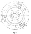
- Fig. 4 is a plan view of the rotary table.
- the set-up shown in Fig. 4 differs from that of Fig. 3 in that three welding heads 12A, 12B and 12C (not shown) are provided equiangularly spaced around the rotary table.
- Each welding head 12A, 12B, 12C is provided with its own supply equipment comprising gas cylinders 19A, 19B, 19C (including some containing argon and some containing carbon dioxide), electrical generating equipment 20A, 20B and 20C for providing the electrical power required by each welding head and other equipment as required. That other equipment may include a supply of welding wire which is fed to the respective welding head through the connector 15.
- gas cylinders 19A, 19B, 19C including some containing argon and some containing carbon dioxide
- electrical generating equipment 20A, 20B and 20C for providing the electrical power required by each welding head and other equipment as required.
- That other equipment may include a supply of welding wire which is fed to the respective welding head through the connector 15.
- the weld between the pipe sections can be formed in one continuous operation.
- Each of the welding heads 12 is driven on its respective carriage around the guide track 14 at the same constant rotational speed.
- the rotary table 5 is driven at the same rotational speed around the axis 8.
- the supply equipment 16 for each head 12 remains radially aligned with its head; as a result of the inclination of the pipeline, there is some movement of the head towards and away from the equipment 16 but that is accommodated by movement of the flexible connector 15.
- weld material is laid down in the innermost portion 3A of the groove, but as rotation continues and one welding head comes to a part of the groove that has already been passed over by another head the weld is built up towards the outermost portion 3B.
- both the welding heads 12 and the table 5 can be constant. If desired, the direction of rotation of the welding heads and the table 5 can be reversed periodically, although it will be understood that such reversal is not necessary from the point of view of maintaining the welding heads adjacent to their respective supply equipment.
- the welding assembly 11 can be released from the pipeline, a further length of pipeline allowed to pass out from the vessel and the process repeated with the top of the pipe section 2 then defining the top of the pipeline 1.
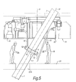
- FIGs. 5 and 6 there is shown a modified form of the apparatus of Figs. 3 and 4 where corresponding parts are designated by the same reference numerals.
- the description referring to Figs. 5 and 6 will be confined mainly to the differences between the arrangement shown there and the arrangement already described with reference to Figs. 3 and 4.
- the supply equipment 16 is suspended from an overhead carousel 25 which is rotatable in the same way as the rotary table 5 in Figs. 3 and 4.
- the platform 51 remains stationary as the welding heads and supply equipment suspended from the carousel rotate, so that a user wishing to watch a welding head must walk round the platform 51.
- the overhead carousel 25 is mounted on a frame 52 which is slidably mounted via wheels 53 on a fixed support frame 54 shown in dotted outline in Fig. 6, whereby the carousel 25 can be moved horizontally away from its operative position, shown in Figs. 5 and 6, to a position clear of the pipeline 1. That may be useful, for example, if it is desired to carry out other operations on a pipeline joint.
- the frame 52 carries a circular guide track 55 interrupted in one region 56 to allow the guide track to be withdrawn horizontally on the frame 52 even when there is a pipe section passing vertically through the track.
- the carousel 25 is mounted for rotation on the guide track 55 by wheels 57 most of which rotate about horizontal axes but two of which (referenced 57A in Fig. 6) rotate about vertical axes. It will be understood that, although the guide track extends around only part of the pipe section, the carousel 25 is able to rotate through a full 360°.
- the carousel 25 shown in Fig. 6 is equipped for the operation of four welding torches (in this particular example two welding heads, each of which has two torches).
- the carousel thus has four sets of supply equipment including gas cylinders 19A, 19B, 19C and 19D for each of the welding heads, electrical control and/or generating equipment 20A, 20B, 20C and 20D and welding wire supplies 21A, 21B, 21C and 21D.
- the apparatus shown in Figs. 5 and 6 operates in substantially the same way as the apparatus of Figs. 3 and 4 and that operation will not be further described here. It should also be understood that whilst various modifications have been described with reference to Figs. 5 and 6, it is possible to provide an apparatus that incorporates only some of those modifications.
- the carousel 25 may be provided as an overhead carousel without providing an arrangement for enabling the carousel to be withdrawn while a pipe section is still present and extending vertically through it.
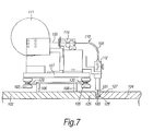
- a welding apparatus 110 having two voltaic arc-welding torches 101 (only one of which can be seen in Figure 7) for butt welding the pipes 102, 104 together.
- the welding torch is of the well known GMAW (gas metal arc welding) and can either be of the type used in MAG (metal active gas) welding or of the type used in MIG (metal inert gas) welding.
- the gas used may for example be carbon dioxide.
- the welding apparatus 110 corresponds to one of the welding heads 12 shown in Figs. 3 to 6 and that the pipes 102, 104 correspond to the pipeline 1 and the pipe section 2 respectively of Figs. 1 to 6.
- the pipes 102, 104 are arranged with their axes aligned and their ends 126, 127 next to each other.
- the ends 126, 127 of the pipes are bevelled so that when brought together they define a circumferentially extending exterior groove 128.
- a track 106 (corresponding to the track 14 of Figs. 3 and 5) is fixedly mounted as a single unit on the left hand pipe 102 (as viewed in Figure 7).
- the track 106 extends circumferentially around the pipe 102.
- the track 106 has two guide tracks 129, 130 that extend around the pipe 102.
- the welding apparatus 110 is mounted for movement along the track 106.
- Wheels 105 are rotatably mounted on a base plate 107 of the welding apparatus 110. The wheels 105 engage with the guide tracks 129, 130 and facilitate the guided movement of the apparatus 110 along the track 106.
- One of the tracks 130 also provides a toothed rack that extends around the pipe.
- a pinion wheel (not shown), mounted for engagement with the rack, is driven so that the apparatus may be driven around the pipe 102.
- the driven pinion wheel may be rotated via a driven chain, which is in turn driven by a stepper motor, or similar driving source (not illustrated).
- the track 106 is so positioned on the pipe 102 that the torches 101 of the apparatus 110 are each positioned directly over the groove 128.
- Such methods of positioning a track and a welding apparatus on a pipe so that a torch of the welding apparatus is correctly positioned over the weld joint to be formed are well known and are therefore not described here in further detail.
- the apparatus 110 is driven around the pipes 102, 104 and the welding torches 101 are operated and controlled so that they deposit weld material in the centre of the groove 128 to form a weld joint 103.
- the weld torches are arranged next to each other.
- the apparatus is started up the first torch (the torch at the front in respect of the initial direction of motion of the torches) is operated first and the other torch is not operated until it reaches the start of the weld laid down by the first torch.
- weld material is deposited in the groove by the first torch to form the weld joint 103 and shortly thereafter further weld material is deposited on top of the weld joint 103 by the second torch.
- the apparatus 110 performs several passes depositing further layers of weld material in the groove to join the pipes together.
- the welding apparatus 110 rotates in both directions around the circumference of the pipes 102, 104.
- the welding apparatus 110 moves around the pipes 102, 104 in one direction (i.e. clockwise or anticlockwise) until it has moved around the entire circumference of the pipes at least once.
- Both torches 101 function in a similar way.
- the following description relates to only one of the two torches and its guidance system, but it will be understood that the other torch functions in substantially the same way.
- Welding wire 109 is continuously fed from a spool 111 of wire to the torch 101.
- the welding wire 109 is unwound from the wire spool 111 by means of a pulling device 114 which conveys the wire 109 via a guiding pipe 108 to a straining device 112, from where the wire is fed into the torch 101.
- the welding of the pipes 102 and 104, by the welding torch is controlled by an automatic guidance system.
- the guidance system guides the welding torch by ascertaining electrical parameter values relating to the voltaic arc impedance.
- the arc impedance depends on, inter alia, the position of the welding arc in relation to the walls defining the groove 128. If the arc lies in the notional central plane (containing the centre line of the groove 128) halfway between the walls of the groove 128, then the influence of those walls on the above electrical parameters is practically identical. On the other hand, if the arc of the voltaic torch 101 is not positioned directly in the centre of the groove 128 the influence of the walls of the groove on the electrical parameter values will be different.
- FIG. 8 illustrates schematically the automatic guidance system of the welding apparatus (illustrated by Figure 7). Each torch is provided with a guidance system, but the system is illustrated and described with reference to a single torch only for the sake of simplicity.
- the guidance system periodically ascertains the electrical parameter values of voltage, current intensity and voltaic arc impedance relating to the right wall and left wall which define the groove 128 (see Figure 1).
- the welding torch is oscillated so that the position of the arc oscillates with a small amplitude (less than a tenth of a millimetre) in a direction substantially parallel to the axis of the pipe (so that the arc moves towards and away from each wall).
- the arc voltage and current are measured practically continuously and signals corresponding to those measured values are passed from the torch 101 via a cable 125 to a governing unit 115.
- the governing unit 115 includes a processing means, which processes the signals.
- the governing unit 115 sends signals representative of the electrical parameter values measured for the left and right walls to two digital filters 116, 118, one filter 116 for generating signals relating to the right wall and one filter 118 for the left wall.
- the governing unit 115 and filters 116, 118 are thus able effectively to extract, from the signals from the torch 101, signals corresponding to values of the parameters measured in respect of the arc in relation to the left wall and right wall, respectively, of the groove 128.
- Output signals are thus produced by the filters 116, 118 relating to the voltage, current and impedance values relating to their respective wall of the groove.
- a difference unit 119 calculates an indication of the position in the groove of the arc of the torch by calculating the differences in the values relating to the left and right walls respectively, determined from the signals received from the filters 116, 118.
- the calculations which are made practically continuously, are used in real time for controlling the position and orientation of the torch 101 in relation to the groove 128.
- a signal is generated which causes a gain unit 121 to activate a command signal, which by means of an amplifier 122, causes a drive unit 123 in association with a centring regulation unit 124 to move the welding torch 101, so that the arc is moved towards the desired location (the centre line of the groove).
- the gain unit 121 does not cause the torch to be moved.
- signals representing the difference values calculated by the difference unit 119 are sent to an integrator unit 120 that is also provided to regulate the positioning of the torch 101 during the welding process. If the position of the arc remains near the central line of the groove 128, and the sum of the distances to the left of the line is practically equal, over time, to the sum of the distances to the right of the line the integrator 120 will not generate any centring movement command signal through the amplifier 122.
- the integrator 120 activates a command signal, which by means of the amplifier 122, causes the drive unit 123 and centring regulation unit 124 to move the welding torch 101, so that the arc is moved towards the desired location (the centre line of the groove).
- the calculations performed by the automatic guidance system may include performing comparisons between calculated values relating to the actual state of the welding system and sample values held in the memory of the guidance system. Such sample values may be entered into the memory manually by keyboard.
- FIG 9 shows schematically a modified form of welding apparatus 210.
- the apparatus 210 operates in a similar manner to that of the apparatus 110 described above.
- the welding torches 201 are aligned so that when the apparatus 210 is mounted on a pipe (not shown in Fig. 9) they both point towards the same notional circumferential line extending around the pipe.
- Wheels 205 are provided for engaging with a guide track (not shown in Fig. 9) that, in use, extends around one of the pipes to be welded.
- the welding wire (not shown) of the apparatus 210 is not provided on the moving part of the apparatus, rather it is mounted at a location remote from the apparatus, and fed from that remote location, via a guide pipe (the connector 15), to the welding apparatus as it moves around the pipe.
- the torches 201 are each water cooled.
- the water is pumped around a cooling system (not shown) including parts of the torch.
- the water heated by the operating torch passes into a heat exchanger, such as a radiator, so that it is cooled.
- Appropriate control means may be provided for synchronising the rotation of the rotary table 5 and the welding assembly 11 and it will be seen that, if desired, the degree of operator involvement in the process can be very limited.
- the number of welding heads 12 used at any one time is preferably at least two but three or more may be used. If three heads are provided, then even if one of them is damaged, the other two may be used simultaneously and that alone enables a considerable increase in welding speed to be achieved.
Landscapes
- Engineering & Computer Science (AREA)
- Physics & Mathematics (AREA)
- Plasma & Fusion (AREA)
- Mechanical Engineering (AREA)
- Butt Welding And Welding Of Specific Article (AREA)
- Arc Welding In General (AREA)
- Lining Or Joining Of Plastics Or The Like (AREA)
Applications Claiming Priority (5)
| Application Number | Priority Date | Filing Date | Title |
|---|---|---|---|
| GBGB9828726.1A GB9828726D0 (en) | 1998-12-24 | 1998-12-24 | Method and apparatus for welding pipes together |
| GB9828726 | 1998-12-24 | ||
| GB9915232A GB2345016B (en) | 1998-12-24 | 1999-06-29 | Method and apparatus for welding pipes together |
| GB9915232 | 1999-06-29 | ||
| EP99969236A EP1148966B1 (fr) | 1998-12-24 | 1999-12-21 | Procede et appareil de soudage de tuyaux |
Related Parent Applications (1)
| Application Number | Title | Priority Date | Filing Date |
|---|---|---|---|
| EP99969236A Division EP1148966B1 (fr) | 1998-12-24 | 1999-12-21 | Procede et appareil de soudage de tuyaux |
Publications (2)
| Publication Number | Publication Date |
|---|---|
| EP1249296A2 true EP1249296A2 (fr) | 2002-10-16 |
| EP1249296A3 EP1249296A3 (fr) | 2005-07-13 |
Family
ID=26314935
Family Applications (3)
| Application Number | Title | Priority Date | Filing Date |
|---|---|---|---|
| EP20020013571 Withdrawn EP1249295A1 (fr) | 1998-12-24 | 1999-12-21 | Méthode et appareil de soudage de tubes |
| EP02013572A Withdrawn EP1249296A3 (fr) | 1998-12-24 | 1999-12-21 | Procédé et appareil de soudage de tubes ensemble |
| EP99969236A Expired - Lifetime EP1148966B1 (fr) | 1998-12-24 | 1999-12-21 | Procede et appareil de soudage de tuyaux |
Family Applications Before (1)
| Application Number | Title | Priority Date | Filing Date |
|---|---|---|---|
| EP20020013571 Withdrawn EP1249295A1 (fr) | 1998-12-24 | 1999-12-21 | Méthode et appareil de soudage de tubes |
Family Applications After (1)
| Application Number | Title | Priority Date | Filing Date |
|---|---|---|---|
| EP99969236A Expired - Lifetime EP1148966B1 (fr) | 1998-12-24 | 1999-12-21 | Procede et appareil de soudage de tuyaux |
Country Status (16)
| Country | Link |
|---|---|
| US (1) | US6313426B2 (fr) |
| EP (3) | EP1249295A1 (fr) |
| AT (1) | ATE222826T1 (fr) |
| AU (1) | AU757996B2 (fr) |
| BR (1) | BR9916572B1 (fr) |
| CA (1) | CA2355624C (fr) |
| DE (1) | DE69902697T2 (fr) |
| DK (1) | DK1148966T3 (fr) |
| ES (1) | ES2183646T3 (fr) |
| GB (1) | GB2345016B (fr) |
| NO (1) | NO320137B1 (fr) |
| NZ (1) | NZ512092A (fr) |
| PT (1) | PT1148966E (fr) |
| RU (1) | RU2236334C2 (fr) |
| TR (1) | TR200101840T2 (fr) |
| WO (1) | WO2000038871A1 (fr) |
Families Citing this family (41)
| Publication number | Priority date | Publication date | Assignee | Title |
|---|---|---|---|---|
| GB9828727D0 (en) † | 1998-12-24 | 1999-02-17 | Saipem Spa | Apparatus and method for welding pipes together |
| NL1011223C2 (nl) * | 1999-02-05 | 2000-08-10 | Allseas Group Sa | Werkwijze en inrichting voor het aan elkaar lassen van twee pijpen. |
| US7114881B2 (en) * | 2000-10-24 | 2006-10-03 | Saipem S.P.A. | Method and apparatus for welding pipes together |
| MY128610A (en) * | 2001-12-31 | 2007-02-28 | Shell Int Research | Method for interconnecting tubulars by forge welding |
| GB0228812D0 (en) * | 2002-12-11 | 2003-01-15 | Hastings Kim P | A welding arrangement |
| AU2003225423A1 (en) † | 2003-02-14 | 2004-09-06 | Heerema Marine Contractors Nederland B.V. | Apparatus and method for joining pipe ends together |
| DE10334446A1 (de) * | 2003-07-29 | 2005-02-17 | Orbitalservice Gmbh | Orbital-Schweißvorrichtung |
| CN1973096B (zh) * | 2003-09-14 | 2011-10-19 | 康克斯科技公司 | 用于将梁架结构焊接到柱的侧面的旋转的方法与设备 |
| FR2894169B1 (fr) * | 2005-12-07 | 2008-04-25 | Serimer Dasa Soc Par Actions S | Dispositif de soudage automatique du type mig/mag |
| AU2006348009B2 (en) * | 2006-09-04 | 2013-05-23 | Heerema Marine Contractors Nederland S.E. | Guiding device |
| FR2914979B1 (fr) * | 2007-04-12 | 2009-07-10 | Saipem S A Sa | Procede de realisation de conduite sous-marine comprenant le martelage de soudures d'assemblage a l'interieur de la conduite |
| US20080302539A1 (en) * | 2007-06-11 | 2008-12-11 | Frank's International, Inc. | Method and apparatus for lengthening a pipe string and installing a pipe string in a borehole |
| FR2920105B1 (fr) * | 2007-08-21 | 2010-02-05 | Saipem Sa | Procede de traitement de soudures de conduite en acier comprenant le martelage des soudures a l'interieur de la conduite |
| US20090050613A1 (en) * | 2007-08-23 | 2009-02-26 | Harvey Prasek | Methods, Apparatus And Products For Welding Rotating Work Pieces |
| US20090065556A1 (en) * | 2007-09-06 | 2009-03-12 | Ge-Hitachi Nucleare Energy Americas Llc | Method to reduce shrinkage driven distortion when welding on pressure piping and vessel materials |
| EP2225067A2 (fr) * | 2007-11-28 | 2010-09-08 | Frank's International, Inc. | Procedes et appareil de formation de colonnes tubulaires |
| GB0801917D0 (en) | 2008-02-01 | 2008-03-12 | Saipem Spa | Method and apparatus for the welding of pipes |
| US8310324B2 (en) * | 2008-04-11 | 2012-11-13 | Will Harris | Releasable guide and methods for using same |
| DE102009020146B3 (de) * | 2009-04-08 | 2010-06-10 | V & M Deutschland Gmbh | Verfahren und Vorrichtung zum Verbinden der Enden von Rohren aus Stahl mittels Orbitalschweißen in Hybridtechnik |
| GB0921078D0 (en) | 2009-12-01 | 2010-01-13 | Saipem Spa | Pipeline welding method and apparatus |
| US20110198318A1 (en) * | 2010-02-12 | 2011-08-18 | General Electric Company | Horizontal welding method and joint structure therefor |
| NL1037804C2 (nl) * | 2010-03-12 | 2011-09-13 | Richard Andr Zurburg | Werkwijze en inrichting voor het assembleren van buizen en fittingen. |
| GB2482693A (en) * | 2010-08-10 | 2012-02-15 | Subsea 7 Ltd | Pipe Welding Apparatus |
| US8950648B2 (en) | 2011-05-07 | 2015-02-10 | Conxtech, Inc. | Box column assembly |
| WO2013076541A1 (fr) * | 2011-11-24 | 2013-05-30 | Weldobot Ltd | Système et procédé de soudage portatif et pistage de ligne de soudure modulaires |
| US11767934B2 (en) | 2013-05-23 | 2023-09-26 | Crc-Evans Pipeline International, Inc. | Internally welded pipes |
| US10589371B2 (en) * | 2013-05-23 | 2020-03-17 | Crc-Evans Pipeline International, Inc. | Rotating welding system and methods |
| US10480862B2 (en) | 2013-05-23 | 2019-11-19 | Crc-Evans Pipeline International, Inc. | Systems and methods for use in welding pipe segments of a pipeline |
| US10695876B2 (en) | 2013-05-23 | 2020-06-30 | Crc-Evans Pipeline International, Inc. | Self-powered welding systems and methods |
| RU2548842C1 (ru) * | 2013-12-05 | 2015-04-20 | Общество с ограниченной ответственностью "Центр лазерных технологий", ООО "ЦЛТ" | Модуль лазерно-дуговой для орбитальной сварки неповоротных кольцевых стыков труб |
| GB201409344D0 (en) * | 2014-05-27 | 2014-07-09 | Proserv Uk Ltd | Subsea welding apparatus and method |
| CN115302042A (zh) | 2014-08-29 | 2022-11-08 | 克里凯文斯管线国际有限公司 | 用于焊接的方法和系统 |
| GB2536419A (en) | 2015-03-10 | 2016-09-21 | Petrofac Ltd | Pipe assembly station |
| AU2015387441B2 (en) * | 2015-03-26 | 2021-06-10 | Crc-Evans Pipeline International, Inc. | Rotating welding system and methods |
| US11458571B2 (en) | 2016-07-01 | 2022-10-04 | Crc-Evans Pipeline International, Inc. | Systems and methods for use in welding pipe segments of a pipeline |
| FR3053755B1 (fr) * | 2016-07-06 | 2018-08-17 | Saipem S.A. | Procede de raccordement de deux elements unitaires d'une conduite sous-marine de transport de fluides soumise a la fatigue |
| GB201700735D0 (en) | 2017-01-16 | 2017-03-01 | Saipem Spa | Welding support block |
| FI20175195L (fi) * | 2017-03-02 | 2018-09-03 | Motocut Oy | Työkoneeseen liitettävä laite metalliprofiilien katkaisemiseksi ja tietokoneohjelmaväline |
| CN112975068A (zh) * | 2019-12-17 | 2021-06-18 | 中国核工业二三建设有限公司 | 高温气冷堆核电站一种球路管道焊接方法 |
| CN113909728A (zh) * | 2021-11-05 | 2022-01-11 | 重庆市大足区群林机械配件厂 | 一种智能消声器加工焊接机 |
| CN114193038A (zh) * | 2021-12-28 | 2022-03-18 | 中国原子能科学研究院 | 一种上管和下管的焊接方法 |
Citations (3)
| Publication number | Priority date | Publication date | Assignee | Title |
|---|---|---|---|---|
| US4319709A (en) * | 1978-11-29 | 1982-03-16 | Compagnie Francaise Des Petroles | Positioning of an additional tubular element on a tubular structure |
| EP0262545A1 (fr) * | 1982-03-31 | 1988-04-06 | N.I.S. Limited | Soudure et pose de pipe-lines |
| US5044825A (en) * | 1988-11-07 | 1991-09-03 | Allseas Engineering B.V. | Method and installation for laying a pipeline |
Family Cites Families (36)
| Publication number | Priority date | Publication date | Assignee | Title |
|---|---|---|---|---|
| US2227194A (en) * | 1939-02-16 | 1940-12-31 | Nat Tube Co | Apparatus for welding |
| US2795689A (en) * | 1954-02-24 | 1957-06-11 | Louis C Mcnutt | Automatic pipe welding apparatus |
| US2956147A (en) * | 1959-02-24 | 1960-10-11 | Roscoe Moss Company | Casing welding apparatus |
| US3515843A (en) * | 1968-02-16 | 1970-06-02 | Nippon Concrete Ind Co Ltd | Automatic welding device for jointing concrete pile sections with steel end plates |
| GB1319239A (en) * | 1969-09-22 | 1973-06-06 | Foster Wheeler Brown Boilers | Automatic arc-welding torches |
| US3727025A (en) * | 1970-03-24 | 1973-04-10 | Rig Hammers Inc | Method for welding vertically extending pipe sections together |
| US3800116A (en) * | 1970-12-29 | 1974-03-26 | Sumitomo Metal Ind | Apparatus for automatically welding pipe joints for cylindrical members such as steel pipe piles |
| US3777115A (en) | 1972-02-22 | 1973-12-04 | Astro Arc Co | Apparatus for controlling electrode oscillation |
| GB1517481A (en) | 1975-07-14 | 1978-07-12 | Matsushita Electric Ind Co Ltd | Follow-up control apparatus for controlling the movement of a welding weaving device |
| US4283617A (en) | 1976-02-03 | 1981-08-11 | Merrick Welding International, Inc. | Automatic pipe welding system |
| US4145593A (en) | 1976-02-03 | 1979-03-20 | Merrick Welding International, Inc. | Automatic pipe welding system |
| GB1576119A (en) * | 1976-06-04 | 1980-10-01 | Foster Wheeler Power Prod | Orbital welding torch for the butt welding of tubes |
| US4380695A (en) | 1976-07-06 | 1983-04-19 | Crutcher Resources Corporation | Control of torch position and travel in automatic welding |
| US4151395A (en) | 1976-07-06 | 1979-04-24 | CRC-Crose, International, Inc. | Method and apparatus for electric arc and analogous welding under precision control |
| US4373125A (en) * | 1977-07-22 | 1983-02-08 | Astro-Arc Company | Apparatus for welding pipes |
| FR2403155A1 (fr) * | 1977-09-20 | 1979-04-13 | Peyrot Jean Pierre | Plate-forme tournante de soudage |
| US4336440A (en) | 1979-07-03 | 1982-06-22 | Westinghouse Electric Corp. | Weld tracking/electronic arc sensing system |
| JPS5791877A (en) | 1980-11-28 | 1982-06-08 | Nippon Kokan Kk <Nkk> | Rotary arc welding method |
| JPS5853375A (ja) | 1981-09-24 | 1983-03-29 | Kobe Steel Ltd | 消耗電極式ア−ク溶接方法 |
| EP0088501B1 (fr) * | 1982-02-12 | 1986-04-16 | United Kingdom Atomic Energy Authority | Soudeuse ou découpeuse à laser pour tubes |
| US4495400A (en) | 1982-04-26 | 1985-01-22 | Crutcher Resources Corporation | Method and apparatus for positioning a welding torch in automatic electric welding |
| JPS58187263A (ja) | 1982-04-26 | 1983-11-01 | Nippon Kokan Kk <Nkk> | ア−ク溶接方法 |
| NL8300207A (nl) * | 1983-01-20 | 1984-08-16 | Berg A P Ingbureau | Inrichting voor het lassen van buizen. |
| JPS59191575A (ja) | 1983-04-13 | 1984-10-30 | Mitsubishi Electric Corp | 溶接線追従装置 |
| US4525616A (en) | 1984-01-03 | 1985-06-25 | Evans Pipeline Equipment Company | Internal pipe welding apparatus |
| US4631386A (en) | 1984-05-14 | 1986-12-23 | Slavens Clyde M | Welding head apparatus |
| JPS62118976A (ja) | 1985-11-18 | 1987-05-30 | Nippon Steel Corp | 開先シ−ム倣い方法 |
| US4990743A (en) | 1989-05-10 | 1991-02-05 | Daihen Corporation | Control method for tracing a weld line in a welding apparatus |
| US5030812A (en) | 1989-06-13 | 1991-07-09 | Nkk Corporation | Method for one-side root pass welding of a pipe joint |
| FR2656555B1 (fr) | 1989-12-29 | 1994-10-28 | Serimer | Systeme mecanique de guidage automatique d'une ou plusieurs torches d'une unite de soudage a l'arc. |
| EP0461203B1 (fr) | 1990-01-04 | 1996-08-28 | CRC-Evans Pipeline International, Inc. | Procede de fonctionnement pour soudage automatique a vitesse elevee |
| AU6185694A (en) * | 1993-05-05 | 1994-11-10 | Atlantic Point Inc. | Method and device for welding pipes to each other |
| US5347101A (en) * | 1994-02-07 | 1994-09-13 | Mcdermott International, Inc. | Automatic tracking system for pipeline welding |
| US5593605A (en) | 1994-10-11 | 1997-01-14 | Crc-Evans Pipeline International, Inc. | Internal laser welder for pipeline |
| US5796069A (en) | 1997-01-10 | 1998-08-18 | Crc-Evans Pipeline International, Inc. | Arc and laser welding process for pipeline |
| IT1292205B1 (it) | 1997-06-26 | 1999-01-25 | Saipem Spa | Procedimento di inseguimento automatico del cianfrino per la saldatura di testa di tubi e apparecchiatura per la realizzazione |
-
1999
- 1999-06-29 GB GB9915232A patent/GB2345016B/en not_active Revoked
- 1999-12-21 DE DE69902697T patent/DE69902697T2/de not_active Expired - Lifetime
- 1999-12-21 WO PCT/EP1999/010504 patent/WO2000038871A1/fr active IP Right Grant
- 1999-12-21 EP EP20020013571 patent/EP1249295A1/fr not_active Withdrawn
- 1999-12-21 PT PT99969236T patent/PT1148966E/pt unknown
- 1999-12-21 RU RU2001120902/02A patent/RU2236334C2/ru not_active IP Right Cessation
- 1999-12-21 NZ NZ512092A patent/NZ512092A/xx unknown
- 1999-12-21 DK DK99969236T patent/DK1148966T3/da active
- 1999-12-21 AU AU27958/00A patent/AU757996B2/en not_active Expired
- 1999-12-21 TR TR2001/01840T patent/TR200101840T2/xx unknown
- 1999-12-21 BR BRPI9916572-4A patent/BR9916572B1/pt not_active IP Right Cessation
- 1999-12-21 ES ES99969236T patent/ES2183646T3/es not_active Expired - Lifetime
- 1999-12-21 CA CA002355624A patent/CA2355624C/fr not_active Expired - Lifetime
- 1999-12-21 EP EP02013572A patent/EP1249296A3/fr not_active Withdrawn
- 1999-12-21 EP EP99969236A patent/EP1148966B1/fr not_active Expired - Lifetime
- 1999-12-21 AT AT99969236T patent/ATE222826T1/de not_active IP Right Cessation
-
2001
- 2001-05-04 US US09/848,433 patent/US6313426B2/en not_active Expired - Lifetime
- 2001-06-22 NO NO20013169A patent/NO320137B1/no not_active IP Right Cessation
Patent Citations (3)
| Publication number | Priority date | Publication date | Assignee | Title |
|---|---|---|---|---|
| US4319709A (en) * | 1978-11-29 | 1982-03-16 | Compagnie Francaise Des Petroles | Positioning of an additional tubular element on a tubular structure |
| EP0262545A1 (fr) * | 1982-03-31 | 1988-04-06 | N.I.S. Limited | Soudure et pose de pipe-lines |
| US5044825A (en) * | 1988-11-07 | 1991-09-03 | Allseas Engineering B.V. | Method and installation for laying a pipeline |
Also Published As
| Publication number | Publication date |
|---|---|
| US6313426B2 (en) | 2001-11-06 |
| TR200101840T2 (tr) | 2001-12-21 |
| NO320137B1 (no) | 2005-10-31 |
| WO2000038871A1 (fr) | 2000-07-06 |
| EP1148966A1 (fr) | 2001-10-31 |
| CA2355624C (fr) | 2005-11-08 |
| BR9916572A (pt) | 2001-10-02 |
| DE69902697D1 (de) | 2002-10-02 |
| DE69902697T2 (de) | 2003-04-10 |
| NO20013169L (no) | 2001-08-20 |
| NO20013169D0 (no) | 2001-06-22 |
| NZ512092A (en) | 2003-02-28 |
| EP1249296A3 (fr) | 2005-07-13 |
| EP1249295A1 (fr) | 2002-10-16 |
| RU2236334C2 (ru) | 2004-09-20 |
| US20010017292A1 (en) | 2001-08-30 |
| PT1148966E (pt) | 2003-01-31 |
| AU757996B2 (en) | 2003-03-13 |
| DK1148966T3 (da) | 2002-12-23 |
| GB9915232D0 (en) | 1999-09-01 |
| CA2355624A1 (fr) | 2000-07-06 |
| AU2795800A (en) | 2000-07-31 |
| ATE222826T1 (de) | 2002-09-15 |
| EP1148966B1 (fr) | 2002-08-28 |
| BR9916572B1 (pt) | 2011-06-28 |
| GB2345016B (en) | 2003-04-02 |
| ES2183646T3 (es) | 2003-03-16 |
| GB2345016A (en) | 2000-06-28 |
Similar Documents
| Publication | Publication Date | Title |
|---|---|---|
| CA2355624C (fr) | Procede et appareil de soudage de tuyaux | |
| CA2355625C (fr) | Appareil et procede de soudage de tuyaux | |
| US7114881B2 (en) | Method and apparatus for welding pipes together | |
| US4176269A (en) | Clamping apparatus for welding circumferential articles | |
| US4001543A (en) | Apparatus for a laser welding of a pipeline, particularly suitable for application on pipe-laying ships | |
| AU2002223635A1 (en) | Method and apparatus for welding pipes together | |
| MX2012008990A (es) | Sistema soldador basdo en corona dentada. | |
| CN214134406U (zh) | 一种圆筒焊缝自动焊接装置 | |
| WO2009126023A1 (fr) | Procédé et appareil de soudure automatisée, et système de soudure | |
| JPH042346B2 (fr) | ||
| US8686316B2 (en) | Automatic welding device of the MIG/MAG type | |
| US6124566A (en) | Automatic tracking process of the joint bevel for the butt welding of pipes and equipment for the embodiment of the process | |
| JPH01224167A (ja) | 鋼管溶接装置 | |
| CA2252688C (fr) | Procede de soudure de tuyaux | |
| JPS5915746B2 (ja) | 枝管溶接装置 | |
| RU2181320C2 (ru) | Способ сварки труб и устройство для его осуществления | |
| CN116393859A (zh) | 大直径取水管道焊接方法 | |
| JPH0359782B2 (fr) | ||
| WO2011112088A1 (fr) | Procédé et système d'assemblage de conduites et de raccords à parois épaisses par soudage automatisé |
Legal Events
| Date | Code | Title | Description |
|---|---|---|---|
| PUAI | Public reference made under article 153(3) epc to a published international application that has entered the european phase |
Free format text: ORIGINAL CODE: 0009012 |
|
| AC | Divisional application: reference to earlier application |
Ref document number: 1148966 Country of ref document: EP |
|
| AK | Designated contracting states |
Kind code of ref document: A2 Designated state(s): AT BE CH CY DE DK ES FI FR GB GR IE IT LI LU MC NL PT SE |
|
| PUAL | Search report despatched |
Free format text: ORIGINAL CODE: 0009013 |
|
| AK | Designated contracting states |
Kind code of ref document: A3 Designated state(s): AT BE CH CY DE DK ES FI FR GB GR IE IT LI LU MC NL PT SE |
|
| STAA | Information on the status of an ep patent application or granted ep patent |
Free format text: STATUS: THE APPLICATION IS DEEMED TO BE WITHDRAWN |
|
| 18D | Application deemed to be withdrawn |
Effective date: 20050701 |