EP1248680B1 - Apparat und verfahren zum mischen und trennen unter benützung magnetischer teilchen - Google Patents
Apparat und verfahren zum mischen und trennen unter benützung magnetischer teilchen Download PDFInfo
- Publication number
- EP1248680B1 EP1248680B1 EP00905525A EP00905525A EP1248680B1 EP 1248680 B1 EP1248680 B1 EP 1248680B1 EP 00905525 A EP00905525 A EP 00905525A EP 00905525 A EP00905525 A EP 00905525A EP 1248680 B1 EP1248680 B1 EP 1248680B1
- Authority
- EP
- European Patent Office
- Prior art keywords
- container
- magnet
- magnetic particles
- magnetic
- mixing
- Prior art date
- Legal status (The legal status is an assumption and is not a legal conclusion. Google has not performed a legal analysis and makes no representation as to the accuracy of the status listed.)
- Expired - Lifetime
Links
Images
Classifications
-
- B—PERFORMING OPERATIONS; TRANSPORTING
- B03—SEPARATION OF SOLID MATERIALS USING LIQUIDS OR USING PNEUMATIC TABLES OR JIGS; MAGNETIC OR ELECTROSTATIC SEPARATION OF SOLID MATERIALS FROM SOLID MATERIALS OR FLUIDS; SEPARATION BY HIGH-VOLTAGE ELECTRIC FIELDS
- B03C—MAGNETIC OR ELECTROSTATIC SEPARATION OF SOLID MATERIALS FROM SOLID MATERIALS OR FLUIDS; SEPARATION BY HIGH-VOLTAGE ELECTRIC FIELDS
- B03C1/00—Magnetic separation
- B03C1/02—Magnetic separation acting directly on the substance being separated
- B03C1/28—Magnetic plugs and dipsticks
- B03C1/288—Magnetic plugs and dipsticks disposed at the outer circumference of a recipient
-
- B—PERFORMING OPERATIONS; TRANSPORTING
- B03—SEPARATION OF SOLID MATERIALS USING LIQUIDS OR USING PNEUMATIC TABLES OR JIGS; MAGNETIC OR ELECTROSTATIC SEPARATION OF SOLID MATERIALS FROM SOLID MATERIALS OR FLUIDS; SEPARATION BY HIGH-VOLTAGE ELECTRIC FIELDS
- B03C—MAGNETIC OR ELECTROSTATIC SEPARATION OF SOLID MATERIALS FROM SOLID MATERIALS OR FLUIDS; SEPARATION BY HIGH-VOLTAGE ELECTRIC FIELDS
- B03C1/00—Magnetic separation
- B03C1/005—Pretreatment specially adapted for magnetic separation
- B03C1/01—Pretreatment specially adapted for magnetic separation by addition of magnetic adjuvants
-
- B—PERFORMING OPERATIONS; TRANSPORTING
- B03—SEPARATION OF SOLID MATERIALS USING LIQUIDS OR USING PNEUMATIC TABLES OR JIGS; MAGNETIC OR ELECTROSTATIC SEPARATION OF SOLID MATERIALS FROM SOLID MATERIALS OR FLUIDS; SEPARATION BY HIGH-VOLTAGE ELECTRIC FIELDS
- B03C—MAGNETIC OR ELECTROSTATIC SEPARATION OF SOLID MATERIALS FROM SOLID MATERIALS OR FLUIDS; SEPARATION BY HIGH-VOLTAGE ELECTRIC FIELDS
- B03C2201/00—Details of magnetic or electrostatic separation
- B03C2201/26—Details of magnetic or electrostatic separation for use in medical or biological applications
Definitions
- the present invention relates to an apparatus and a method for mixing and separation of magnetic Particles for the purpose of isolating substances of interest from a nonmagnetic liquid test medium.
- Magnetic separation of biomolecules and cells based on magnetic particles and employing biospecific affinity reactions is advantageous in terms of selectivity, simplicity, and speed.
- the technique has proved to be quite useful in analytical and preparative biotechnology and is now being increasingly used for bioassays and isolation of target substances such as cells, proteins, nucleic acid sequences and the like.
- the term "receptor” refers to any substance or group of substances having biospecific binding affinity for a given liquid, to the substantial exclusion of other substances.
- the receptors susceptible to biospecific binding affinity reactions are antibodies (both monoclonal and polyclonol), antibody fragments, enzymes, nucleic acids, lectins and the like.
- ligand refers to substances such as antigens, haptens, and various cell associated structures having at least one characteristic determinant or epitope, which substances are capable of being biospecifically recognized by and bound to a receptor.
- target substance refers to either member of a biospecific binding affinity pair, i.e., a pair of substances or a substance and a structure exhibiting a mutual affinity of interaction, and includes such things as biological cells or cell components, biospecific ligands, and receptors.
- Affinity separation refers to known process techniques where a target substance mixed with other substances in a liquid medium is bound to the surface of a solid phase by a biospecific affinity binding reaction. Substances, which lack the specific molecule or structure of the target substance, are not bound to the solid phase and can be removed to effect the separation of the bound substance or vice versa. Small particles, particularly polymeric spherical particles as solid phase, have proved to be quite useful, as they can be conveniently coated with biomolecules, provide a very high surface area, and give reasonable reaction kinetics. Separations of the particles containing bound target substance (bound material) from the liquid medium (free material) may be accomplished by filtration or gravitational effects, e.g., settling, or by centrifugation.
- Magnetizable particles which allows the particle bound substance to be separated by applying a magnetic field.
- Small magnetizable particles are well known in the art as their use in the separations involving immunological and other biospecific affinity reactions.
- Small magnetizable particles generally fall into two broad categories. The first category includes particles that are permanently magnetized, and the second comprises particles that become magnetic only when subjected to a magnetic field. The latter are referred to as paramagnetic or superparamagnetic particles and are usually preferred over the permanently magnetized particles.
- the surface of paramagnetic particles is coated with a suitable ligand or receptor, such as antibodies, lectins, oligonucleotides, or other bioreactive molecules, which can selectively bind a target substance in a mixture with other substances.
- a suitable ligand or receptor such as antibodies, lectins, oligonucleotides, or other bioreactive molecules, which can selectively bind a target substance in a mixture with other substances.
- suitable ligand or receptor such as antibodies, lectins, oligonucleotides, or other bioreactive molecules
- the magnetic separation process typically involves mixing the sample with paramagnetic particles in a liquid medium to bind the target substance by affinity reaction, and then separating the bound particle/target complex from the sample medium by applying a magnetic field. All magnetic particles except those particles that are colloidal, settle in time.
- the liquid medium therefore, must be agitated to some degree to keep the particles suspended for a sufficient period of time to allow the bioaffmity binding reaction to occur. Examples of known agitation methods include shaking, swirling, rocking, rotation, or similar manipulations of a partially filled container.
- the affinity bond between the target substance and the paramagnetic particles is relatively weak so as to be disrupted by strong turbulence in the liquid medium.
- biological target substances such as cells, cellular fractions, and enzyme complexes are extremely fragile and will likewise be disrupted or denatured by excess turbulence.
- U.S. Patent No. 4,910,148 describes a device and method for separating cancer cells from healthy cells.
- Immunoreactive paramagnetic particles and bone marrow cells are mixed by agitating the liquid medium on a rocking platform. Once the particles have bound to the cancer cells, they are separated from the liquid medium by magnets located externally on the platform. Although such mixing minimizes the liquid turbulence, it does not provide an efficient degree of contact between the particles and the target substance.
- the utility of this device is limited to the separation of cells from relatively large sample volumes.
- U.S. Patent No. 5,238,812 describes a complicated device for rapid mixing to enhance bioaffinity binding reactions employing a U-tube-like structure as mixer.
- the U-tube is rapidly, rocked or rotated for 5 to 15 seconds to mix the magnetic particles in the test medium, and then a magnet is brought in close proximity to the bottom of the U-tube to separate the magnetic particles.
- its utility is limited to treating very small volumes ( ⁇ 1000 ⁇ l) of test medium.
- U.S. Patent No. 5,336,760 describes a mixing and magnetic separation device comprising a chamber attached to a platform with one or more magnets located close to the container and an intricate mechanism of gears and motor to rotate the platform.
- Immunoreactive paramagnetic particles are mixed in the test medium by first placing a stainless steel "keeper" between the chamber and the magnet to shield it from the magnetic field. Then the platform is rotated between vertical and horizontal positions. The particles in the test medium are mixed by end-over-end movement of the chamber. Following the mixing, the "keeper” is removed so that the magnetic particles are captured by the exposed magnetic field. Beside requiring a complicated mechanism, agitation of the liquid medium by end-over-end rotation does not mix relatively buoyant particles efficiently, and the liquid turbulence will tend to shear off or damage the target substance.
- U.S. Patent No. 5,110,624 relates to a method of preparing magnetizable porous particles and describes a flow-through magnetically stabilized fluidized bed (MSFB) column to isolate proteins from cell lysate.
- MSFB flow-through magnetically stabilized fluidized bed
- the MSFB column is loosely packed with a bed of magnetizable particles and equipped with means of creating a stationary magnetic field that runs parallel to the flow of solution through the column.
- the particles are maintained in a magnetically stabilized fluidized bed by adjusting the rate of flow of the solution and the strength of the magnetic field.
- This is a complicated technique requiring precise adjustment of the flow rate and magnetic strength so that the combined effect of fluid velocity and magnetic attraction exactly counterbalances the effect of gravity on the particles.
- the design of MSFB is not optimized for use with small test volumes, and cannot be made optimal for applications such as bioassays or cell separations.
- the application teaches that alternately energizing and de-energizing the two electromagnets at a sufficiently rapid rate keeps the particles suspended in the center of the chamber.
- This method limits movement of the particles to a relatively small distance, significantly reducing the collision frequency between particles and the target substance, necessary for affinity binding which is a major reason for mixing the paramagnetic particles in the liquid medium.
- a significant fraction of the particles, particularly particle-cell complexes may escape the magnetic field by gravitational settling to the bottom of chamber and will be lost during aspiration of the liquid medium following the aggregation step.
- Japanese patent No. JP58193687 entitled Agitation And Separation Of Microscopic Material is directed to separation of microorganisms by mixing magnetized ultra-fine magnetic wire with microorganisms containing magnetic particles. The mixing is accomplished by a rotary magnetic field which also acts to separate the microorganisms after a mixing step.
- This patent is concerned with separation of microorganisms that contain internally ultra-fine magnetic particles.
- microorganisms are well known in the art, a particular example being magneto spirillium, a bacteria known to synthesize ultra fine magnetic particles. Such microorganisms would not and cannot be used as magnetic particles for mixing and separation of a target species as envisioned by the present invention.
- the Japanese patent's requirement for linearly-connected ultra-fine magnetic particles refers to a wire which is most likely used to create a high gradient magnetic field (HGMF) to collect or precipitate the magnetite-containing bacteria over the surface of these wires.
- HGMF high gradient magnetic field
- the applicable known procedures have shortcomings, including the requirement for separate mechanically complex mixing mechanisms, as well as various process constraints and inefficiencies.
- the present invention provides devices and methods for magnetic mixing and separation which are of relatively simple construction and operation, which can be adapted to process large or small volumes of test liquid, and which can process multiple test samples simultaneously.
- the invention provides a single device for both mixing and separation and a method which maximizes the mixing efficiency of the paramagnetic particles in the liquid medium without causing detrimental liquid turbulence.
- the affinity separation of a target substance from a liquid test medium is carried out by mixing magnetic particles bearing surface immobilized ligands or receptors to promote specific affinity binding reaction between the magnetic particles and the target substance.
- the liquid test medium with the magnetic particles in a suitable container is removably mounted in the apparatus of the present invention.
- a single magnetic field gradient is created in the liquid test medium. This gradient induces the magnetic particles to move towards the inside Wall of the container nearest to the magnetic source. Relative angular movement between the magnetic source and the aggregating magnetic particles is started to mix the magnetic particles in the test medium and is continued for a sufficient time to ensure optimum binding of the target substance by affinity reaction.
- the magnetic source is moved longitudinally along the container.
- the magnetic particles are immobilized as a relatively compact aggregate on the inside wall of the container nearest to the magnetic source.
- the test medium may then be removed while the magnetic particles are retained on the wall of the container and may be subjected to further processing, as desired.
- the invention permits rapid, efficient, and clean separation of a target substance from test media and is particularly useful in the affinity magnetic separations of organic, biochemical, or cellular components of interest from, for example, assay reaction mixtures, cell cultures, body fluids and the like.
- the invention includes a novel mixing system wherein the magnetic particles are mixed within a relatively motionless test liquid by magnetic means disposed external to the container holding the test liquid.
- the invention also includes an apparatus and method wherein magnetic particles while mixing and confused in a magnetic zone are concurrently linearly displaced to scan large volumes of test medium for affinity separation with a small concentration of magnetic particles.
- the invention provides an apparatus in which both the processes of mixing and separation are carried out by a common magnetic means disposed in a single apparatus, thereby making it simpler and more practical to use.
- the apparatus of the invention comprises the features of claim 1.
- the container for performing the described mixing and separation is preferably of cylindrical configuration, made of a nonmagnetic material such as glass or plastic.
- the container has at least one opening for receiving the test medium containing the magnetic particles.
- the magnetic means may comprise one or more permanent or electromagnets disposed externally to the container for generating magnetic field gradients within the liquid test medium.
- the magnet is a permanent magnet of a rare earth alloy such as anisotropic sintered materials composed of neodymium-iron-boron or samarium-cobalt.
- the magnet is disposed external to the container so as to define a magnetic field gradient cavity in a desired cross-section of the test medium.
- the term cavity is employed because the magnetic field gradient acts to confine or concentrate the magnetic particles much as were enclosed within a cavity.
- the distance between the magnet and the container is adjustable so as to create a desired magnetic field strength within the magnetic field cavity of the test medium.
- the apparatus may include means for adjusting the distance between a magnet and the container.
- the magnetic field strength in the cavity is normally stronger at a part of the internal surface of the container closer to the magnet (locus of magnetic force) than it is elsewhere in the cavity and becomes negligible outside the cavity.
- magnetic particles near this locus are subject to considerably greater magnetic force than those farther from it.
- two magnets may be located on the opposite sides of the container, preferably with similar magnetic poles facing each other, to distort the magnetic flux lines and generate two magnetic field gradients and two loci of magnetic force forming in one cavity.
- Such an arrangement is particularly useful for agitating magnetic particles, as described below.
- an assembly comprising a vertical array of magnets are positioned exterior to the container to create multiple magnetic field gradient cavities within desired cross-sections of the test medium.
- the present invention provides for agitating and mixing the magnetic particles within the test medium while maintaining the test medium substantially motionless with respect to the container.
- the magnetic particles are moved through the test medium by rotating the container with respect to a stationary magnet defining a stationary magnetic field gradient cavity. This motion induces an angular movement in the magnetic particles relative to the substantially motionless test medium caused by the change in angular position between the aggregated particles within the container and the magnet.
- the magnetic particles are also moved within the test medium by moving a magnet defining a moving magnetic field gradient cavity along a container. This movement induces an angular movement of the particles relative to the substantially motionless test medium caused by the change in angular position between the magnet and the aggregated particles.
- a motionless magnetic field gradient cavity with respect to particles tends to aggregate the magnetic particles in the test medium as a relatively compact mass on the inner surface of the lateral wall of the container closest to magnetic means. As the particles are all clustered in the vicinity of the magnetic means, they also tend to stick to each other by non-magnetic forces of compression and surface tension. The degree of compression naturally depends on the force of magnetic attraction and is particularly relevant in the case of particles with diameters of a few microns, such as are usually employed in affinity separation. Such compacted particles can remain aggregated even after the removal of the magnetic field and usually require vigorous shaking of the test medium to re-disperse. A carefully balanced magnetic field strength in the test medium will pull the particles out of suspension into an aggregate, but will not be so strong as to overly compress the aggregate.
- the aggregated mass of particles move with the wall of the container to a position of weaker magnetic field.
- the stronger magnetic field in the vicinity of the magnetic means begins to pull off the particles from the aggregated mass, the trajectories of the particles being, pulled off depending on the angular position of the aggregated mass and magnet.
- the particles As the particles are pulled, they move and form chains of particles, due to the induced magnetic dipole on the particles by the applied magnetic field. As the chains accelerate towards the magnet, fluid drag forces cause them to break creating a cloud of magnetic particles in the fluid medium.
- the relative angular position between the magnet and the internal surface of the container bearing the aggregated particles recedes continuously and causes the particles to move ceaselessly in angular trajectories within the test medium thereby enabling the re-suspension and mixing of magnetic particles.
- the displacement of particle trajectories in a continuous manner is based on the action of magnetomotive force acting at a continuously changing angle between the magnet and the paramagnetic particles which results in a mixing process without fluid turbulence. Furthermore, this mixing process significantly increases the collision frequency between the particles and target species thereby enhancing the efficiency of the affinity binding reaction.
- the break-up of particle chains as described above may be aided by providing additional means to abruptly change the polarity of the magnet. For example, if the north pole of the magnet is facing the container, it may be flipped to the south pole. The repulsive forces generated by such sudden reversal of a magnet pole aids in the breakup of a particle chain. Such magnet pole flipping may be accomplished by any rotation device. The frequency of flipping may vary is desired.
- a specific rate of change in the angular position of the container and magnet i.e., speed of rotation
- speed of rotation to ensure re-suspension and mixing to a large extent depend on the size, density and magnetic susceptibility of the particles, the cross sectional diameter of the container, the density and viscosity of the fluid test medium and the strength of the magnetic field.
- particles it should be noted that the force pulling a magnetic particle through a fluid medium is the product of its magnetic saturation and field gradient and the viscous force opposing particle motion, which is governed by Stokes Law.
- a suitable speed of rotation can be calculated on the basis of forces of gravity, buoyancy, fluid friction and magnetism.
- the intensity of the magnetic field or fields and the appropriate speed of rotation will be modulated experimentally. It should be noted that too high a rotation speed will not allow the particles sufficient time to detach from the aggregated mass and particles will be spread over the circumference of the inner wall of the container. Similarly, too slow a rotation speed will produce a rolling mass of the aggregated particles. In both cases, re-suspension and mixing of the particles will be prevented.
- the field strength in the magnetic field cavity of the test medium must also be balanced so as to allow the aggregated particles to move with the wall of the container. It will be appreciated that a fixed magnet position is inconvenient when the desired particle size may vary considerably. In such situations, it is advantageous to be able to adjust the distance between the magnet and the container to create the optimum field, strength in the magnetic field cavity of the fluid medium.
- a continuous rotation in the sense described above usually provides satisfactory mixing of magnetic particles
- the relative angular position may be changed to 90 or 180 degrees in a single step. Such steps may be repeated more than once. If desired, time delays may be imposed between such steps.
- the separation of magnetic particles from the liquid test medium in accordance with the invention is effected by stopping the rotation of the magnet with respect to the container to terminate the agitation of the magnetic particles.
- the magnetic particles within the magnetic field gradient in the fluid medium are attracted to and immobilized at the inside wall of the container nearest to the magnet.
- Applicant's invention utilizes a new principle of which has allowed, for the first time, integration of a simplified mixing and separation process into a single device.
- the present invention provides many advantages over the prior art devices for affinity magnetic separation.
- the mixing of the present invention provides a high rate of contact between the affinity surface of the magnetic particles and the target substance, thereby enhancing the affinity bonding, without causing fluid turbulence.
- the hydrodynamic shear forces remain low and will not affect the affinity bond between particle and target substance complex or prevent denaturation, or other damage to the target substance.
- the process of the present invention can be used for sample volumes as little as 100 ⁇ L and can be scaled up to process sample volumes in excess of 100mL.
- the present invention is particularly useful for the isolation of human rare cells required in various cell therapies as it permits a level of operating efficiency which has not been achievable before this.
- the purity and yield of the target substance obtained by a particular affinity magnetic separation is largely determined by the mixing process employed to promote the affinity binding reaction between the target substance and the surface of the magnetic particles.
- the binding reactions require a close contact between the affinity surface and the target substance.
- the rate of the reaction largely depends on the collision frequency between the two entities and the rate of surface renewal of the magnetic particles.
- the surface renewal is the process of removing the thin layer of media at the affinity surface and exchanging it with fresh media from the bulk.
- the hydrodynamic shear force at the affinity surface therefore, must be carefully balanced so that it is sufficient to remove the thin layer of media without disrupting the affinity bonds. This has been difficult to achieve by past mixing methods based on agitating the fluid medium.
- the present invention provides a high collision frequency and a substantially balanced shear force by magnetically inducing a controlled movement of the magnetic particles in an essentially motionless fluid medium.
- the particle concentration is, typically, much greater than the target substance to enhance the yield of the target substance. This is particularly important in the isolation of rare cell types such as mammalian hemopoietic cells where a particle to cell ratio of 20:1 may be required to obtain a desired isolation efficiency. In such applications, magnetic beads of uniform size distribution are required. The high cost of these beads are widely appreciated.
- the ability to isolate highly purified stem cells may serve in the treatment of lymphomas and leukemias as well as other neoplastic conditions.
- processing of large sample volumes is required. Such a process consumes large quantities of magnetic beads. Thus there is a need to reduce the concentration of magnetic beads without sacrificing the required high purity and yield.
- the present invention is capable of treating large sample volumes by relatively small concentrations of paramagnetic particles by combining a vertically moving magnet along the length of the container while the container is rotating.
- the mixing and separation process of the present invention have particular utility in various laboratory and clinical procedures involving biospecific affinity binding reactions for separations.
- magnetic particles are used which have their surface coated with one member of a specific affinity binding pair, i.e. ligand or receptor, capable of specifically binding a substance of interest in the test medium.
- Such biospecific affinity binding reactions may be employed for the determination or isolation of a wide range of target substances in biological samples.
- target substances are, cells, cell components, cell subpopulations (both eukaryotic and prokaryotic), bacteria, viruses, parasites, antigens, specific antibodies, nucleic acid sequences and the like.
- the apparatus and method of the invention may be used to carry out immunospecific cell separations for the analysis or isolation of cells including, by way of example: tumor cells from bone marrow; T-lymphocytes from peripheral blood or bone marrow; lymphocyte subsets, such as CD2, CD4, CD8, and CD34 from peripheral blood, monocytes; granulocytes and other cell types.
- the removal or depletion of various cell types may be carried out in a similar manner.
- the invention may be also be used in the separation or, analysis of various bacteria or parasites from food products, culture media, body fluids and the like.
- the apparatus and method of the present invention may be used in: bioassays including immunoassays and nucleic acid probe assays; isolation and detection of DNA and mRNA directly from crude cell lysate; and isolation and detection of proteins.
- the magnetic particles preferred for the practice of the invention are noncolloidal paramagnetic or superparamagnetic particles.
- Such magnetic particles are typically of polymeric material containing a small amount of ferro-magnetic substance such as iron-based oxides, e.g., magnetite, transition metals, or rare earth elements, which causes them to be captured by a magnetic field.
- the paramagnetic particles useful for practicing the invention should provide for an adequate binding surface capacity for the adsorption or covalent coupling of one member of a specific affinity binding pair, i.e. ligand or receptor.
- the preferred diameter of a particle is typically in the range between 0.1 to 300 ⁇ m. Suitable paramagnetic particles are commercially available from Dynal Inc.
- the preferred particles are of uniform size between about 1 and 5 ⁇ m in diameter, and contain magnetizable material evenly dispersed throughout. Such particles may be obtained from Dynal under the identification numbers M-280 and M- 450 by Dynal Inc. These beads are coated with a thin shell of polystyrene which provides a defined surface for the immobilization of various ligands or receptors. Such immobilization may be carried out by any one of many well-known techniques; techniques employing either physical adsorption or covalent coupling chemistry are preferred.
- the magnetic field gradients may be generated by one or more permanent magnet(s) or electromagnet(s).
- Permanent magnets are generally preferred for use in laboratory-scale operations and for automated devices employed in clinical diagnostics are preferred.
- larger scale devices or automated devices such as those employed in pharmaceutical or industrial production can be more advantageously produced using electromagnets, since the field gradients can be more easily altered under automatic control to effect various processing steps.
- Permanent magnets for practicing the invention preferably have a surface field strength sufficient to attract a majority of the magnetic particles.
- Permanent magnets of rare earth alloys having a surface field strength in the range of several hundred Gauss to several kilo-Gauss are preferred.
- High energy permanent magnets made from Neodymium-Iron-Boron or Samarium-Cobalt magnets and characterized by BHmax (maximum energy product) in the range of 25 to 45 MGOe (megaGauss Oersted) are particularly preferred.
- Such magnets may be obtained from International Magnaproducts Inc., of Valparaiso, IN, and many other commercial sources.
- the permanent magnets have a rectangular cross-section and may be glued or fixed by mechanical means to a nonmagnetic holding support to form a permanent magnet assembly.
- the assembly may include a ferromagnetic harness to house the magnet or magnets and to intensify and focus the magnetic field.
- the magnets are preferably oriented with their magnetic lines of force perpendicular to the vertical axis of the container. Alternate cross-sectional shapes, orientations, and magnetic pole orientation with respect to the container are also envisioned.
- the permanent magnet assembly is placed in close proximity to the container without the magnet extending to the bottom of the container.
- the distance between each magnet and the container shown in Figures 2 and 3 is adjustable between about 1 mm to about 20 mm to create a desired magnetic field strength within the magnetic field cavity of the test medium.
- the apparatus shown in these figures includes a means for adjusting the distance between each magnet assembly and the container. Depending on the size and magnetic susceptibility of the particles and the field strength of the magnets and cross-section diameter of the container, the appropriate distance will be determined experimentally.
- the field strength created in the magnet field cavities should be carefully balanced so that it is sufficient to pull the particles out of suspension, aggregate the particles on the side of the container, and allow the aggregated particles to move with the wall of the container.
- the magnet may be moved closer to the container, as discussed, to increase the field strength in order to separate the particles from the liquid test medium.
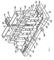
- Figure 3 illustrates a preferred embodiment of the present invention for processing a plurality of test liquid media simultaneously. It includes a linear drive mechanism mounted on a positioning mechanism and a rotation mechanism. The three mechanisms allow vertical linear movement of a magnet assembly, adjustment of the distance between the magnet assembly and containers, and rotation of the containers. Simultaneous container rotation and linear magnet movement provides the advantage of processing large volumes of test media with a relatively small quantity of magnetic particles.
- the apparatus of Figure 3 consists of two main parts, linear drive assembly 111 and base assembly 112. Both assemblies are constructed of a nonmagnetic material, aluminum being preferred.
- the linear drive assembly 111 comprises a rigid frame 113 with two fixed guide rods 114 and 115 and a centrally located screw shaft 116.
- the end portions of screw 116 are smooth and un-threaded and are mounted in two centrally located ends flanges (not shown).
- the screw 116 is freely rotatable and includes a roll nut (not shown) which moves linearly in the vertical plane, either up or down, upon rotation of screw 116.
- a pulley 117 is fixed to the smooth portion of screw 116 protruding from the top plate 138 of frame 113 and is connected by a timing belt 118 to another pulley 119 fixed to the shaft of a variable speed electric motor 120 mounted on bracket 121 of frame 113.
- Timing belt 118 is made of neoprene or urethane with precisely formed grooves on the inner side. The belt width and groove pitch match the dimensions of the teeth on pulleys 117 and 119 to provide positive and non-slip power transmission. Suitable timing belts and gear pulleys may be obtained from Stock Drive Products, New Hyde Park, NY or from other similar vendors.
- a carriage 122 is fixed on the roll nut (not shown) of screw 116. Its vertical motion is ensured by the accurately aligned guide rods 115 and 114.
- Linear drive assembly 111 is attached to base assembly 112 by bolting the bottom plate 139 of frame 113 to a linear slide mechanism 123.
- a rod with a knob 128 inserted through a center hole of the base assembly 112 is attached to the linear slide mechanism 123.
- the linear slide mechanism 123 thus can be moved forward or backward by pulling or pushing the knob 128 to position it at a desired distance from the containers 124.
- a magnet assembly 125 with magnets 126 is removably mounted on the linear drive carriage 122 by means of three evenly spaced screws 127. This is advantageous because magnets of varying size and geometry can be easily exchanged.
- the magnets 126 are aligned with the row of containers 124. Their distance from the containers is adjusted by pulling or pushing the knob 128.
- the motor 120 rotates the screw 116.
- the roll nut (not shown) converts this rotary motion to a linear motion moving magnet assembly 125 vertically.
- the direction of the linear movement of magnet assembly 125 is controlled by the clockwise or counter-clockwise rotation of the motor 120 by a motor controller (not shown).
- the movement of magnet assembly 125, either upward or downward can thus be controlled at will and may be repeated for as many cycles as desired.
- the position and the stroke length of the linear up and down movement of the carriage 122 may be controlled by two position sensors (not shown) to control the lowest and highest extremes of travel of the carriage 125.
- An electronic signal from these sensors may be used to reverse the motor rotation, thereby causing a repeated scanning for a desired length of the containers 124 by their corresponding magnets 126.
- Electronic motor controllers and position sensor are well known in the art and may be obtained from any one of a number of vendors. If permanent magnets are employed, they are preferably a rare earth type as described above and have suitable dimensions and geometries so as to define a magnetic field cavity of a desired field strength which provides a desired cross-section within the liquid test medium in each container.
- the base assembly 112 includes a mechanism for rotation comprising a variable speed electric motor 129 with a gear pulley 130 fixed to its shaft.
- a pulley rotor 131 is attached to each one of a plurality of holder 134.
- a timing belt 132 is wrapped around the gear teeth of pulley 130 and each of the rotors 131.
- Only one rotor 131 is shown next to a holder 134 for a container 124, it should be understood that each container holder 134 has a rotor 131 associated with it which is driven by the belt 132.
- the motor 129 and rotor pulleys 130, 131 are secured in their precise positions by a top metal plate 133 fixed to base assembly 112.
- the gear pulley rotors 131 are free rotating and their respective shafts protrude from corresponding holes in plate 133.
- the belt width and the inner groove pitch of the timing belt 132 dimensionally match with gear teeth of the motor gear pulley 130 and the rotors 131 to provide positive and non-slip power transmission.
- idling rollers may be installed between the pulleys to increase the wrap around the gear teeth for a firmer non-slip power transmission.
- the motor 129 rotates the timing belt 132 thereby simultaneously rotating all pulley rotors 131.
- Holders 134 are removably mounted on the tapered end of a rotor shaft 135 protruding from corresponding holes in plate 133 and provide means for funny holding containers 124 in a substantially vertical position.
- a removable holder design is advantageous as it provides a convenient means to accommodate a variety of container sizes on the apparatus by simply changing the holders to correspond to the container geometry.
- the position of the magnet assembly 125 may be adjusted to a required distance from the row of containers 124.
- the motor 129 rotates containers 124 around their vertical axes. As containers 124 rotate, the relative angular position of the aggregating magnetic particles in each container with respect to its corresponding magnet 126 is continuously altered, inducing the magnetic particles to mix within the cavity of the magnetic field gradient, as described above. While the containers 124 are rotating, motor 120 may be switched on to move the magnets 126 up and down in the vertical plane thereby moving the magnetic field cavity in alignment with the vertical axis of the containers. Upon reaching a desired length of the container, the direction of movement of magnet assembly 125 is reversed. This process is repeated for the entire duration of particle mixing.
- the motor 129 may be an electric step motor to provide a step-wise change of a predetermined distance in the relative angular position such as described above.
- motor 120 may be an electric step motor to provide a step-wise change of a predetermined distance in the vertical plane.
- Various combinations of continuous and step-movement for the rotation and linear movement maybe utilized. In every case the optimum speed of rotation and linear movement will be determined by trial and error.
- the linear drive motor 120 is turned off.
- the magnet assembly 125 is brought to a home position.
- the rotation drive motor 129 is turned off.
- the magnetic particles in the containers 124 are attracted to and immobilized at the inside wall closest to the magnets 126.
- the aggregation of the magnetic particles on the vertical side of the container 124 facilitates removal of the test medium by aspiration or similar methods.
- magnet assembly 125 may be moved closer to containers 124 by moving knob 128. This tightly aggregates the magnetic particles on the walls of the containers 124 to facilitates a clean removal of the test medium.
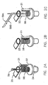
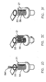
- FIG. 2A shows two electromagnet coils 101a and 101b mounted on a support frame 104 and displaced at about 180 degrees at the exterior of a container 102 with the liquid test medium and magnetic particles 103 inside.
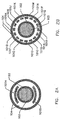
- Figure 2B shows a cross-section of a single container 102 with the liquid test medium and magnetic particles 103 surrounded by a ring of individual electromagnet coils 101a to 101r mounted on a support frame 104.
- the exact number of sequential electromagnets employed will depend on the size of the container 102 and other parameters.
- the angular movement from one magnet to the other in its simplest form is 180 degrees so that the magnetic particles in the test medium 103 will move in relatively straight lines back and forth across the container 102. More variety is preferably added to the paths of the magnetic particles by modulating the polarity, as well as the power level of the electric current, thereby altering the direction of the magnetic poles with alterations of the magnetic field.
- the container defining the mixing and separation chamber includes at least one opening for the addition and removal of a test medium.
- the container is preferably of substantially cylindrical form and made from a magnetically permeable material such as plastic or glass. Additionally, the inside surface of the chamber may be biocompatible and, if desired, the chamber may be sterilized for aseptic processing of the test media.
- the volume of the container is not critical as long as an adequate magnetic field gradient can be provided to accommodate the chamber and, particularly, can accommodate the desired cross-section of the liquid test medium inside.
- the container used to hold the test medium may be a test tube or an eppendorf type of tube with a conical bottom.
- the volumetric capacity of the test tube is preferably between 250 ⁇ l to about 18 ml as usually employed in research laboratories.
- the various configurations of apparatus as described above can be easily scaled up to process much larger volumes of liquid test media as may be required for clinical applications. In all cases, the size and geometry of the magnet is adjusted to generate an adequate magnetic field strength within the field cavity of the test medium inside a particular size of container.
- embodiments of the present invention particularly suited for use in the research laboratory preferably employ readily removable and replaceable containers such as test tubes
- diagnostic and other devices employing the teachings of the present invention might employ permanent flow cells or other non-removable chambers for mixing and separation.
- the relative angular movement is induced in the magnetic particles by either rotating a magnetic field around a stationary container or rotating the container relative to an immobile magnetic field.
- the magnet creating the field is disposed outside the container and defines a cavity of magnetic field gradient within the liquid test medium.
- Any container configuration may be utilized, such as, for example, a doughnut-shaped container. In such a container the magnetic source may be "outside" of the container and “within” the container, if it occupies the hole of the doughnut. Therefore, it is to be understood that, within the scope of the appended claims, the invention may be practiced other-wise than as specifically described herein.
Landscapes
- Apparatus Associated With Microorganisms And Enzymes (AREA)
- Mixers With Rotating Receptacles And Mixers With Vibration Mechanisms (AREA)
- Physical Or Chemical Processes And Apparatus (AREA)
Claims (21)
- Apparat zum Mischen magnetischer Teilchen in und zum Trennen magnetischer Teilchen von einem flüssigen Medium mit
einem magnetisch durchlässigen Behälter (124) mit Wandungen für die Aufnahme eines flüssigen Mediums und einer Menge in der Flüssigkeit befindlicher magnetischer Teilchen (58),
einem außenseitig der Wandungen des Behälters (124) angeordneten Magneten (126), der in dem Behälter (124) in einem Teil des flüssigen Mediums einen Magnetfeldgradienten erzeugt, wodurch in dem flüssigen Medium ein Magnetfeldhohlraum begrenzt wird,
Einrichtungen (129) für die Änderung der relativen Winkellage zwischen den magnetischen Teilchen (58) in dem Behälter (124) und dem Magneten (126), wodurch eine Bewegung der magnetischen Teilchen (58) im gesamten Magnetfeldhohlraum in dem flüssigen Medium verursacht wird,
dadurch gekennzeichnet, daß der Apparat Einrichtungen (116,117, 118,119,121) aufweist zur einmaligen oder wiederholten Bewegung des Magneten (126) über eine Längsentfernung entlang der Außenseite der Umfangswand des Behälters (124) gleichzeitig mit der Änderung der relativen Winkellage zwischen den magnetischen Teilchen (58) und dem Magneten (126), wodurch der Magnetfeldhohlraum gleichzeitig mit der Bewegung der magnetischen Teilchen (58) in dem Magnetfeldhohlraum zu einer Längsbewegung in dem flüssigen Medium in dem Behälter (124) veranlaßt wird. - Misch- und Trennapparat des Anspruchs 1, der zum Mischen und Trennen magnetischer Teilchen geeignet ist, deren Durchmesser in dem Bereich von etwa 0,1 µm bis etwa 300 µm liegen kann.
- Misch- und Trennapparat des Anspruchs 1, bei dem der Magnet eine Stärke in dem Bereich von etwa 200 Gauß bis etwa 5000 Gauß haben kann.
- Misch- und Trennapparat des Anspruchs 1, ferner mit Einrichtungen zur Bewegung des Magneten dichter an die Wandungen des Behälters oder weiter weg von diesen.
- Misch- und Trennapparat des Anspruchs 1, bei dem die Einrichtungen zur kontinuierlichen Änderung der relativen Winkellage für die kontinuierliche Drehung des Behälters um eine konzentrische Achse relativ zu einem stationären Magneten mit 10 bis 200 Umdrehungen/Minute eingerichtet sind.
- Misch- und Trennapparat des Anspruchs 1, bei dem die Einrichtungen zur Bewegung des Magneten von einem Ende des flüssigen Mediums zu dem anderen den Magneten kontinuierlich bewegen.
- Misch- und Trennapparat des Anspruchs 1, bei dem der Behälter um seine konzentrische Achse stufenweise gedreht wird.
- Misch- und Trennapparat des Anspruchs 1, bei dem die stufenweise Drehbewegung des Behälters einen vorbestimmten Zeitverzug zwischen den Stufeninkrementen beinhaltet.
- Misch- und Trennapparat des Anspruchs 1, bei dem die Einrichtungen für die Bewegung des Magneten von einem Ende des flüssigen Mediums zu dem anderen den Magneten in Stufeninkrementen bewegen.
- Misch- und Trennapparat des Anspruchs 9, bei dem die Stufeninkrement-Bewegung des Magneten einen vorbestimmten Zeitverzug zwischen den Stufeninkrementen beinhaltet.
- Misch- und Trennapparat des Anspruchs 1, bei dem der Behälter mehrere Behälter zur Aufnahme einer Menge magnetischer Teilchen umfaßt, die in je einem der Behälter angeordnet ist, ein Magnet außenseitig jedes der genannten mehreren Behälter angeordnet ist, jeder Behälter eine Einrichtung zur Änderung der relativen Winkellage hat, und jeder der genannten Magnete eine Einrichtung zur Bewegung des Magneten von einem Ende des flüssigen Mediums zu dem anderen hat.
- Verbessertes Verfahren der Mischung affinitätsreaktionsfähiger magnetischer Teilchen (58) in einem flüssigen Testmedium in einem Behälter (124), bei dem eine Affinitätsbindungsreaktion zwischen einer Zielsubstanz in dem flüssigen Testmedium und den magnetischen Teilchen (58) veranlaßt wird, bei dem der Kontakt zwischen der Affinitätsoberfläche der magnetischen Teilchen (58) und der Zielsubstanz ohne Flüssigkeitsturbulenz dadurch maximiert wird, daß man das flüssige Medium in Bezug auf den Behälter (124) im wesentlichen bewegungslos hält, mit den Stufen der
Einbringung des flüssigen Testmediums und der magnetischen Teilchen (58) in einen magnetisch durchlässigen Behälter (124) mit Wandungen,
Erzeugung eines Magnetfeldgradienten innerhalb des Behälters (124) in einem Teil des flüssigen Testmediums, um einen Magnetfeldhohlraum in dem flüssigen Medium durch einen Magneten (126) zu begrenzen, der außenseitig der genannten Wandungen längs eines Teils des Behälters (124) angeordnet ist,
Einstellung der Feldstärke in dem Magnetfeldhohlraum durch Einstellung des Abstandes zwischen dem Magneten (126) und dem Behälter (124),
Veränderung der relativen Winkellage zwischen den sich auf den Wandungen des Behälters (124) zusammenballenden magnetischen Teilchen (58) und dem Magneten (126), um eine Vermischung der magnetischen Teilchen (58) mit dem flüssigen Testmedium in dem magnetischen Hohlraum zu veranlassen, und
Bewegung des Magneten (126) in Längsrichtung über eine vertikale Länge des Behälters (124) gleichzeitig mit der Stufe der Winkeländerung, um eine gewünschte Länge des in dem Behälter (124) enthaltenen flüssigen Testmediums mit dem die in Bewegung befindlichen magnetischen Teilchen (58) enthaltenden Magnetfeldhohlraum abzutasten. - Verfahren nach Anspruch 12, bei dem die Stufe der Längsbewegung des Magneten über eine vertikale Länge des Behälters (124) so oft wie gewünscht wiederholt wird.
- Verfahren nach Anspruch 12 oder 13, bei dem die Stufe der Längsbewegung des Magneten über eine vertikale Länge des Behälters (124) ferner die Veränderung der genannten Bewegungslänge entlang dem flüssigen Testmedium beinhaltet.
- Verfahren nach Anspruch 12, ferner mit den folgenden Stufen:Anhalten der Stufe der Längsbewegung des Magneten (126) über eine vertikale Länge des Behälters (124) in einer gewünschten Lage entlang der Länge des Behälters (124),Konstanthalten der relativen Winkellage des Magneten (126) und der magnetischen Teilchen (58) in dem Behälter (124), wodurch die magnetischen Teilchen (58) aus dem flüssigen Testmedium auf einer Innenfläche des Behälters (124) konzentriert werden,Bewegen des Magneten (126) dichter an die Wandung des Behälters (124), um die fest zusammengeballten magnetischen Teilchen (58) fest zusammenzuballen, undEntfernen der Flüssigkeit aus dem Behälter (124) ohne Störung der konzentrierten magnetischen Teilchen (58).
- Verfahren nach einem der vorhergehenden Ansprüche 12 bis 15, bei dem die Stufe der Veränderung der relativen Winkellage zwischen den magnetischen Teilchen (58) und dem Magneten (126) die Drehung des Behälters (124) um eine Längsachse durch den Behälter (124) relativ zu einem stationären Magneten (126) mit einer Winkelgeschwindigkeit von 10 bis 200 Umdrehungen/Minute umfaßt.
- Verfahren nach einem der vorhergehenden Ansprüche 12 bis 15, bei dem die Stufe der Veränderung der relativen Winkellage zwischen den magnetischen Teilchen (58) und dem Magneten (126) die zusatzweise Drehung des Behälters (124) um eine Längsachse durch den Behälter (124) relativ zu einem stationären Magneten (126) in vorgewählten Winkelschritten bei vorgewählten Zeitverzügen zwischen den Schritten umfaßt.
- Verfahren nach einem der vorhergehenden Ansprüche 12 bis 17, bei dem die Stufe der Erzeugung eines magnetischen Feldgradienten die Anordnung mehrerer durch Winkelzwischenräume beabstandeter Elektromagnete außenseitig und entlang der Umfangswand des Behälters (124) umfaßt, und bei dem die Stufe der Veränderung der relativen Winkellage zwischen den magnetischen Teilchen (58) und dem Magneten (126) die Erregung der Mehrzahl der Magnete (126) der Reihe nach entlang der Umfangswand des Behälters (124) umfaßt.
- Verfahren nach Anspruch 12, ferner mit der Stufe der Erzeugung wenigstens eines zusätzlichen Magnetfeldgradienten in dem Behälter (124) bei einer anderen Lage des flüssigen Mediums, um wenigstens zwei getrennte Magnetfeldhohlräume in dem flüssigen Medium zu begrenzen.
- Verfahren nach Anspruch 12, bei dem der Magnet (126) in Längsrichtung kontinuierlich über eine vertikale Länge des Behälters bewegt wird.
- Verfahren nach Anspruch 12, bei dem der Magnet (126) in Längsrichtung über eine vertikale Länge des Behälters (124) in Zuwachsstufen mit vorbestimmten Zeitverzügen zwischen den Stufen bewegt wird.
Applications Claiming Priority (1)
| Application Number | Priority Date | Filing Date | Title |
|---|---|---|---|
| PCT/US2000/000071 WO2001049419A1 (en) | 2000-01-04 | 2000-01-04 | Apparatus and method for mixing and separation employing magnetic particles |
Publications (2)
| Publication Number | Publication Date |
|---|---|
| EP1248680A1 EP1248680A1 (de) | 2002-10-16 |
| EP1248680B1 true EP1248680B1 (de) | 2005-10-12 |
Family
ID=21740942
Family Applications (1)
| Application Number | Title | Priority Date | Filing Date |
|---|---|---|---|
| EP00905525A Expired - Lifetime EP1248680B1 (de) | 2000-01-04 | 2000-01-04 | Apparat und verfahren zum mischen und trennen unter benützung magnetischer teilchen |
Country Status (5)
| Country | Link |
|---|---|
| EP (1) | EP1248680B1 (de) |
| JP (1) | JP4651894B2 (de) |
| AT (1) | ATE306328T1 (de) |
| DE (1) | DE60023185T2 (de) |
| WO (1) | WO2001049419A1 (de) |
Cited By (2)
| Publication number | Priority date | Publication date | Assignee | Title |
|---|---|---|---|---|
| US7847932B2 (en) | 2007-12-28 | 2010-12-07 | Morpho Detection, Inc. | System and method for improved biodetection |
| US7852470B2 (en) | 2007-12-28 | 2010-12-14 | Morpho Detection, Inc. | System and method for improved biodetection |
Families Citing this family (23)
| Publication number | Priority date | Publication date | Assignee | Title |
|---|---|---|---|---|
| US7718072B2 (en) | 2002-04-26 | 2010-05-18 | Abbott Laboratories | Structure and method for handling magnetic particles in biological assays |
| CN1280428C (zh) * | 2003-05-19 | 2006-10-18 | 清华大学 | 一种基于微小颗粒的生物芯片系统及其应用 |
| JP5385131B2 (ja) * | 2006-06-21 | 2014-01-08 | スピノミックス エス.エイ. | 液体媒体中で磁性粒子を操作及び混合するためのデバイス及び方法 |
| JP4586054B2 (ja) * | 2007-08-31 | 2010-11-24 | 株式会社日立ハイテクノロジーズ | 自動分析装置 |
| GB0717452D0 (en) * | 2007-09-07 | 2007-10-17 | Mole Genetics As | Separation apparatus |
| JP2009066476A (ja) * | 2007-09-11 | 2009-04-02 | Tamagawa Seiki Co Ltd | 液体中の磁性粒子の集合/分散方法及び装置 |
| US8053250B2 (en) * | 2008-06-27 | 2011-11-08 | Rex Chin-Yih Hong | Method and system for suppressing bindings on magnetic particles |
| WO2010117458A1 (en) | 2009-04-10 | 2010-10-14 | President And Fellows Of Harvard College | Manipulation of particles in channels |
| WO2013048546A1 (en) * | 2011-03-29 | 2013-04-04 | Yongxin Zhang | Multifunctional bioreactor system and methods for cell sorting and culturing |
| JP2012152734A (ja) * | 2012-02-14 | 2012-08-16 | Tamagawa Seiki Co Ltd | 液体中の磁性粒子の集合/分散装置 |
| JP2012152213A (ja) * | 2012-02-14 | 2012-08-16 | Tamagawa Seiki Co Ltd | 液体中の磁性粒子の集合/分散装置 |
| JP5347121B2 (ja) * | 2012-02-14 | 2013-11-20 | 多摩川精機株式会社 | 液体中の磁性粒子の集合/分散装置 |
| JP6350654B2 (ja) * | 2014-05-23 | 2018-07-04 | 株式会社島津製作所 | 磁性体粒子の操作方法 |
| WO2015177934A1 (ja) * | 2014-05-23 | 2015-11-26 | 株式会社島津製作所 | 磁性体粒子の操作方法および磁性体粒子操作用デバイス |
| JP2018161649A (ja) * | 2018-04-10 | 2018-10-18 | 株式会社島津製作所 | 磁性体粒子の操作方法および磁性体粒子操作用デバイス |
| US11406989B2 (en) * | 2018-04-25 | 2022-08-09 | Zymo Research Corporation | Apparatus and methods centrifugal and magnetic sample isolation |
| US11262352B2 (en) | 2018-07-20 | 2022-03-01 | Cornell University | Magnetic separation of biological entities from fluid sample |
| CN110346556B (zh) * | 2019-07-15 | 2023-02-17 | 深圳海思安生物技术有限公司 | 一种液体检测试剂及其使用方法 |
| CN110423676B (zh) * | 2019-08-13 | 2023-04-14 | 华东理工大学 | 用于细胞体外培养的磁控生物反应器系统 |
| EP4065260A4 (de) * | 2019-11-27 | 2023-08-02 | JBS Science Inc. | Verfahren und vorrichtung zum mischen von magnetischen teilchen in einem flüssigen medium |
| US20230096792A1 (en) * | 2020-03-02 | 2023-03-30 | Dh Technologies Development Pte. Ltd. | Electromagnetic sampling device protected in a septum piercing needle |
| KR20220156956A (ko) * | 2020-04-03 | 2022-11-28 | 베크만 컬터, 인코포레이티드 | 유체들을 프로세싱하기 위한 전자기 조립체들 |
| US20240392226A1 (en) * | 2020-10-12 | 2024-11-28 | Life Technologies As | Magnetic particle processing systems for use with biological cells and related methods |
Family Cites Families (4)
| Publication number | Priority date | Publication date | Assignee | Title |
|---|---|---|---|---|
| US3985649A (en) * | 1974-11-25 | 1976-10-12 | Eddelman Roy T | Ferromagnetic separation process and material |
| JPS5753257A (en) * | 1980-09-16 | 1982-03-30 | Tohoku Metal Ind Ltd | Apparatus for separating magnetic particulate body |
| JPS58193687A (ja) * | 1982-05-10 | 1983-11-11 | Res Dev Corp Of Japan | 微小物の撹拌分離方法 |
| JP3962789B2 (ja) * | 1995-02-21 | 2007-08-22 | ダブリュー. シディキー,イクバール | 磁性粒子を利用した混合/分離装置及びその方法 |
-
2000
- 2000-01-04 AT AT00905525T patent/ATE306328T1/de not_active IP Right Cessation
- 2000-01-04 WO PCT/US2000/000071 patent/WO2001049419A1/en not_active Ceased
- 2000-01-04 JP JP2001549777A patent/JP4651894B2/ja not_active Expired - Fee Related
- 2000-01-04 DE DE60023185T patent/DE60023185T2/de not_active Expired - Lifetime
- 2000-01-04 EP EP00905525A patent/EP1248680B1/de not_active Expired - Lifetime
Cited By (2)
| Publication number | Priority date | Publication date | Assignee | Title |
|---|---|---|---|---|
| US7847932B2 (en) | 2007-12-28 | 2010-12-07 | Morpho Detection, Inc. | System and method for improved biodetection |
| US7852470B2 (en) | 2007-12-28 | 2010-12-14 | Morpho Detection, Inc. | System and method for improved biodetection |
Also Published As
| Publication number | Publication date |
|---|---|
| WO2001049419A1 (en) | 2001-07-12 |
| DE60023185T2 (de) | 2006-05-11 |
| JP2003519008A (ja) | 2003-06-17 |
| DE60023185D1 (de) | 2006-02-23 |
| ATE306328T1 (de) | 2005-10-15 |
| EP1248680A1 (de) | 2002-10-16 |
| JP4651894B2 (ja) | 2011-03-16 |
Similar Documents
| Publication | Publication Date | Title |
|---|---|---|
| US6231760B1 (en) | Apparatus for mixing and separation employing magnetic particles | |
| US6500343B2 (en) | Method for mixing and separation employing magnetic particles | |
| EP1248680B1 (de) | Apparat und verfahren zum mischen und trennen unter benützung magnetischer teilchen | |
| US7517457B2 (en) | Method of mixing magnetic particles | |
| US20030127396A1 (en) | Apparatus and method for processing magnetic particles | |
| US5795470A (en) | Magnetic separation apparatus | |
| JP6030197B2 (ja) | 液体媒体中で磁性粒子を操作及び混合するためのデバイス及び方法 | |
| US7056657B2 (en) | Apparatus and methods for magnetic separation | |
| JP3085709B2 (ja) | 磁気分離機、磁気分離方法、リガンド測定方法ならびに分離方法 | |
| US6312910B1 (en) | Multistage electromagnetic separator for purifying cells, chemicals and protein structures | |
| US6346196B1 (en) | Flow-through, hybrid magnetic field gradient, rotating wall device for enhanced colloidal magnetic affinity separations | |
| WO2011027146A2 (en) | Ultrasound & magnetic method | |
| JP2010535625A (ja) | 溶液において粒子を縣濁または再縣濁するための方法、およびそれに適応した装置 | |
| US20150153259A1 (en) | Multi-parameter high gradient magnetic separator and methods of use thereof | |
| US20250035520A1 (en) | Apparatus for magnetic purification of biological samples |
Legal Events
| Date | Code | Title | Description |
|---|---|---|---|
| PUAI | Public reference made under article 153(3) epc to a published international application that has entered the european phase |
Free format text: ORIGINAL CODE: 0009012 |
|
| 17P | Request for examination filed |
Effective date: 20020805 |
|
| AK | Designated contracting states |
Kind code of ref document: A1 Designated state(s): AT BE CH CY DE DK ES FI FR GB GR IE IT LI LU MC NL PT SE |
|
| RAP1 | Party data changed (applicant data changed or rights of an application transferred) |
Owner name: SIGRIS RESEARCH, INC. |
|
| RIN1 | Information on inventor provided before grant (corrected) |
Inventor name: SIDDIQI, IQBAL WAHEED |
|
| GRAP | Despatch of communication of intention to grant a patent |
Free format text: ORIGINAL CODE: EPIDOSNIGR1 |
|
| GRAS | Grant fee paid |
Free format text: ORIGINAL CODE: EPIDOSNIGR3 |
|
| GRAA | (expected) grant |
Free format text: ORIGINAL CODE: 0009210 |
|
| AK | Designated contracting states |
Kind code of ref document: B1 Designated state(s): AT BE CH CY DE DK ES FI FR GB GR IE IT LI LU MC NL PT SE |
|
| PG25 | Lapsed in a contracting state [announced via postgrant information from national office to epo] |
Ref country code: FI Free format text: LAPSE BECAUSE OF FAILURE TO SUBMIT A TRANSLATION OF THE DESCRIPTION OR TO PAY THE FEE WITHIN THE PRESCRIBED TIME-LIMIT Effective date: 20051012 Ref country code: NL Free format text: LAPSE BECAUSE OF FAILURE TO SUBMIT A TRANSLATION OF THE DESCRIPTION OR TO PAY THE FEE WITHIN THE PRESCRIBED TIME-LIMIT Effective date: 20051012 Ref country code: BE Free format text: LAPSE BECAUSE OF FAILURE TO SUBMIT A TRANSLATION OF THE DESCRIPTION OR TO PAY THE FEE WITHIN THE PRESCRIBED TIME-LIMIT Effective date: 20051012 Ref country code: AT Free format text: LAPSE BECAUSE OF FAILURE TO SUBMIT A TRANSLATION OF THE DESCRIPTION OR TO PAY THE FEE WITHIN THE PRESCRIBED TIME-LIMIT Effective date: 20051012 |
|
| REG | Reference to a national code |
Ref country code: GB Ref legal event code: FG4D |
|
| REG | Reference to a national code |
Ref country code: CH Ref legal event code: EP |
|
| REG | Reference to a national code |
Ref country code: CH Ref legal event code: NV Representative=s name: WILLIAM BLANC & CIE CONSEILS EN PROPRIETE INDUSTRI |
|
| REG | Reference to a national code |
Ref country code: IE Ref legal event code: FG4D |
|
| PG25 | Lapsed in a contracting state [announced via postgrant information from national office to epo] |
Ref country code: IE Free format text: LAPSE BECAUSE OF NON-PAYMENT OF DUE FEES Effective date: 20060104 |
|
| PG25 | Lapsed in a contracting state [announced via postgrant information from national office to epo] |
Ref country code: DK Free format text: LAPSE BECAUSE OF FAILURE TO SUBMIT A TRANSLATION OF THE DESCRIPTION OR TO PAY THE FEE WITHIN THE PRESCRIBED TIME-LIMIT Effective date: 20060112 Ref country code: GR Free format text: LAPSE BECAUSE OF FAILURE TO SUBMIT A TRANSLATION OF THE DESCRIPTION OR TO PAY THE FEE WITHIN THE PRESCRIBED TIME-LIMIT Effective date: 20060112 Ref country code: SE Free format text: LAPSE BECAUSE OF FAILURE TO SUBMIT A TRANSLATION OF THE DESCRIPTION OR TO PAY THE FEE WITHIN THE PRESCRIBED TIME-LIMIT Effective date: 20060112 |
|
| PG25 | Lapsed in a contracting state [announced via postgrant information from national office to epo] |
Ref country code: ES Free format text: LAPSE BECAUSE OF FAILURE TO SUBMIT A TRANSLATION OF THE DESCRIPTION OR TO PAY THE FEE WITHIN THE PRESCRIBED TIME-LIMIT Effective date: 20060123 |
|
| PG25 | Lapsed in a contracting state [announced via postgrant information from national office to epo] |
Ref country code: MC Free format text: LAPSE BECAUSE OF NON-PAYMENT OF DUE FEES Effective date: 20060131 Ref country code: LU Free format text: LAPSE BECAUSE OF NON-PAYMENT OF DUE FEES Effective date: 20060131 |
|
| REF | Corresponds to: |
Ref document number: 60023185 Country of ref document: DE Date of ref document: 20060223 Kind code of ref document: P |
|
| PG25 | Lapsed in a contracting state [announced via postgrant information from national office to epo] |
Ref country code: PT Free format text: LAPSE BECAUSE OF FAILURE TO SUBMIT A TRANSLATION OF THE DESCRIPTION OR TO PAY THE FEE WITHIN THE PRESCRIBED TIME-LIMIT Effective date: 20060313 |
|
| NLV1 | Nl: lapsed or annulled due to failure to fulfill the requirements of art. 29p and 29m of the patents act | ||
| ET | Fr: translation filed | ||
| PLBE | No opposition filed within time limit |
Free format text: ORIGINAL CODE: 0009261 |
|
| STAA | Information on the status of an ep patent application or granted ep patent |
Free format text: STATUS: NO OPPOSITION FILED WITHIN TIME LIMIT |
|
| 26N | No opposition filed |
Effective date: 20060713 |
|
| REG | Reference to a national code |
Ref country code: IE Ref legal event code: MM4A |
|
| PG25 | Lapsed in a contracting state [announced via postgrant information from national office to epo] |
Ref country code: CY Free format text: LAPSE BECAUSE OF FAILURE TO SUBMIT A TRANSLATION OF THE DESCRIPTION OR TO PAY THE FEE WITHIN THE PRESCRIBED TIME-LIMIT Effective date: 20051012 |
|
| REG | Reference to a national code |
Ref country code: CH Ref legal event code: PFA Owner name: SIGRIS RESEARCH, INC. Free format text: SIGRIS RESEARCH, INC.#130 LILAC LANE#BREA, CALIFORNIA 92821 (US) -TRANSFER TO- SIGRIS RESEARCH, INC.#130 LILAC LANE#BREA, CALIFORNIA 92821 (US) |
|
| REG | Reference to a national code |
Ref country code: GB Ref legal event code: S72Z Free format text: CLAIM LODGED; PATENTS COURT ON 3 NOVEMBER 2010 (HC 10 C03537) |
|
| REG | Reference to a national code |
Ref country code: CH Ref legal event code: PCAR Free format text: NOVAGRAAF SWITZERLAND SA;CHEMIN DE L'ECHO 3;1213 ONEX (CH) |
|
| REG | Reference to a national code |
Ref country code: DE Ref legal event code: R082 Ref document number: 60023185 Country of ref document: DE Representative=s name: DF-MP DOERRIES FRANK-MOLNIA & POHLMAN PATENTAN, DE Ref country code: DE Ref legal event code: R082 Ref document number: 60023185 Country of ref document: DE Representative=s name: DF-MP, DE |
|
| REG | Reference to a national code |
Ref country code: GB Ref legal event code: S72Z Free format text: CLAIM FOR REVOCATION LODGED AT THE PATENTS COURT ON 3 NOVEMBER 2010, DISMISSED BY CONSENT ORDER DATED 12 AUGUST 2011(HC10C03537) |
|
| REG | Reference to a national code |
Ref country code: FR Ref legal event code: PLFP Year of fee payment: 16 |
|
| REG | Reference to a national code |
Ref country code: FR Ref legal event code: PLFP Year of fee payment: 17 |
|
| PGFP | Annual fee paid to national office [announced via postgrant information from national office to epo] |
Ref country code: DE Payment date: 20160120 Year of fee payment: 17 Ref country code: CH Payment date: 20160120 Year of fee payment: 17 Ref country code: IT Payment date: 20160127 Year of fee payment: 17 |
|
| PGFP | Annual fee paid to national office [announced via postgrant information from national office to epo] |
Ref country code: FR Payment date: 20160121 Year of fee payment: 17 Ref country code: GB Payment date: 20160120 Year of fee payment: 17 |
|
| REG | Reference to a national code |
Ref country code: DE Ref legal event code: R119 Ref document number: 60023185 Country of ref document: DE |
|
| REG | Reference to a national code |
Ref country code: CH Ref legal event code: PL |
|
| GBPC | Gb: european patent ceased through non-payment of renewal fee |
Effective date: 20170104 |
|
| REG | Reference to a national code |
Ref country code: FR Ref legal event code: ST Effective date: 20170929 |
|
| PG25 | Lapsed in a contracting state [announced via postgrant information from national office to epo] |
Ref country code: CH Free format text: LAPSE BECAUSE OF NON-PAYMENT OF DUE FEES Effective date: 20170131 Ref country code: FR Free format text: LAPSE BECAUSE OF NON-PAYMENT OF DUE FEES Effective date: 20170131 Ref country code: LI Free format text: LAPSE BECAUSE OF NON-PAYMENT OF DUE FEES Effective date: 20170131 |
|
| PG25 | Lapsed in a contracting state [announced via postgrant information from national office to epo] |
Ref country code: GB Free format text: LAPSE BECAUSE OF NON-PAYMENT OF DUE FEES Effective date: 20170104 Ref country code: DE Free format text: LAPSE BECAUSE OF NON-PAYMENT OF DUE FEES Effective date: 20170801 |
|
| PG25 | Lapsed in a contracting state [announced via postgrant information from national office to epo] |
Ref country code: IT Free format text: LAPSE BECAUSE OF NON-PAYMENT OF DUE FEES Effective date: 20170104 |