EP1248161A2 - Walzenkonstruktion für den Betrieb unter erhöhten Temperaturen - Google Patents
Walzenkonstruktion für den Betrieb unter erhöhten Temperaturen Download PDFInfo
- Publication number
- EP1248161A2 EP1248161A2 EP02005332A EP02005332A EP1248161A2 EP 1248161 A2 EP1248161 A2 EP 1248161A2 EP 02005332 A EP02005332 A EP 02005332A EP 02005332 A EP02005332 A EP 02005332A EP 1248161 A2 EP1248161 A2 EP 1248161A2
- Authority
- EP
- European Patent Office
- Prior art keywords
- roller
- tube
- dovetail
- coefficient
- thermal expansion
- Prior art date
- Legal status (The legal status is an assumption and is not a legal conclusion. Google has not performed a legal analysis and makes no representation as to the accuracy of the status listed.)
- Withdrawn
Links
Images



Classifications
-
- G—PHYSICS
- G03—PHOTOGRAPHY; CINEMATOGRAPHY; ANALOGOUS TECHNIQUES USING WAVES OTHER THAN OPTICAL WAVES; ELECTROGRAPHY; HOLOGRAPHY
- G03G—ELECTROGRAPHY; ELECTROPHOTOGRAPHY; MAGNETOGRAPHY
- G03G15/00—Apparatus for electrographic processes using a charge pattern
- G03G15/20—Apparatus for electrographic processes using a charge pattern for fixing, e.g. by using heat
- G03G15/2003—Apparatus for electrographic processes using a charge pattern for fixing, e.g. by using heat using heat
- G03G15/2014—Apparatus for electrographic processes using a charge pattern for fixing, e.g. by using heat using heat using contact heat
- G03G15/2053—Structural details of heat elements, e.g. structure of roller or belt, eddy current, induction heating
-
- F—MECHANICAL ENGINEERING; LIGHTING; HEATING; WEAPONS; BLASTING
- F16—ENGINEERING ELEMENTS AND UNITS; GENERAL MEASURES FOR PRODUCING AND MAINTAINING EFFECTIVE FUNCTIONING OF MACHINES OR INSTALLATIONS; THERMAL INSULATION IN GENERAL
- F16C—SHAFTS; FLEXIBLE SHAFTS; ELEMENTS OR CRANKSHAFT MECHANISMS; ROTARY BODIES OTHER THAN GEARING ELEMENTS; BEARINGS
- F16C13/00—Rolls, drums, discs, or the like; Bearings or mountings therefor
Definitions
- the present invention relates generally to rolls, for example for Use in fixation devices of reproductive devices, and in particular one Construction of fusing, pressure or heating rollers that take place at elevated temperatures operate.
- Fuser rollers or heat rollers are used that include two end caps that are made of Stainless steel can be used, the end caps with a thermally conductive tube are connected, such as aluminum or copper or alloys of these two Materials.
- end caps that are made of Stainless steel can be used, the end caps with a thermally conductive tube are connected, such as aluminum or copper or alloys of these two Materials.
- There are many known methods to close the end caps with the pipe connect e.g. by mechanical screwing, press fit, circlips, Welding etc. If the end caps and the tube are made of the same material exist, forming techniques such as casting or forging can be used, as far as no joining techniques are required.
- Friction welding is either with or without Force connection carried out. If the end cap or the end plug and that Pipe include materials that are weldable, then a Butt welding processes can be used (see EP 0 395 385). If the End cap and the tube include materials that are not readily weldable then a dovetail connection can be used (see US 5,094,613).
- the present invention relates to a Fuser roller construction in a reproduction device (for operation at temperatures between 204 ° C and 400 ° C (400 ° F and 750 ° F)), a tube with a End plug is connected in a way that essentially separates the Prevented roller from the end pin.
- the roller includes a general elongated, essentially cylindrical tube. To seal the ends of the cylindrical spigot are provided. Every end plug is in turn connected to one end of the cylindrical tube such that after formation a welded connection between the cylindrical tube and the end plug of the Closing pin enters a press connection, which prevents the cylindrical Pipe from the end plug due to a higher operating temperature occurring creep separates.
- roller 10 is generally as an elongated, substantially cylindrical tube 12 formed with end caps or end plug 14th is provided to seal the respective ends of the tube.
- the roller 10 will typically e.g. as a fuser roller or as a pressure roller for one Fixing device used to mark particle images on receiving elements in one fix electrostatographic reproduction device, or as a heating roller for a such fixing roller.
- the roller can be provided with a suitable coating, for example with a suitable fluoroelastomer.
- the roller 10 may be under extreme, extreme conditions Operating conditions, for example in the temperature range of approximately 204 ° C to 400 ° C (400 ° F to 750 ° F). Therefore, the tube 12 and the end plug 14 are made of Materials that are best suited for the functions that these items should perceive.
- the tube 12 must have good thermal conductivity properties so that the Heat quickly reaches the surface of the pipe to carry out the fixing process (i.e. the melting of the marking particles so that they penetrate the surface of a Receiving elements can penetrate, or heating the outer surface of a Fuser).
- the end pins 14 are made of a heat-insulating material designed to prevent heat from escaping at the ends of the tube and the Damaged shaft or other related elements of excessive Exposed to heat.
- the end plug must also have a have appropriate strength and hardness to transmit torques and as To serve storage space.
- roller 10 is typically constructed so that the End plug 14 with the tube 12 using the usual friction welding technology be welded. Under the tougher operating conditions with increased Temperatures fail friction welding connections according to the prior art.
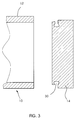
- the friction welding connection is made using an enclosed one Dovetail can be made. 2 the enclosed dovetail is included provided with the reference numeral 20, in Fig. 3 the enclosed dovetail reference numeral 30, and in Fig. 4 is the enclosed dovetail provided with the reference numeral 40.
- the friction welded joint with enclosed Dovetail has the task of facing away from the end pin 14 To prevent expansion of the tube 12 substantially.
- the enclosed one Dovetail prevents the press fit from creeping by loosening the entire connection is pressurized at elevated temperatures.
- rollers for fixing devices that operate at the above temperatures of approx. 204 ° C to 400 ° C (400 ° F to 750 ° F) can be extended significantly. This is important, since fusing rollers of this type are usually reused (i.e. rollers get a corresponding one if the original coating wears out Surface coating) to keep the total cost of ownership of the reproducing device low to keep.
- the tube 12 of the fixing roller consists of a material which has a significantly different coefficient of thermal expansion than the material from which the end plug 14 is made.
- the general operating temperature of the fuser roller core is in the range of approx. 204 ° C and 400 ° C (400 ° F to 750 ° F).
- the pipe material can be aluminum, which has a coefficient of thermal expansion of 23.4x10 -6 / K, while the pin material consists of type 304 stainless steel (or series 200 or 300), which has a coefficient of thermal expansion of 17.28x10 - 6 / K has. The coefficient of thermal expansion of the pipe material is therefore significantly greater than that of the end plug.
- the welded connection according to the invention comprises an enclosed one Dovetail.
- the dovetail is so designed that it does Aluminum tube 12 picks up and it essentially prevents itself due to expansion to move away from the end pin 14 and from this separate.
- 2 and 3 are exploded views to better illustrate the enclosed dovetail.
- the is enclosed Dovetail 20 is a double dovetail that is parallel to the longitudinal axis of the End pin 14 runs. When the friction weld connection is formed, material runs from the end of the tube 12 into the double areas of the dovetail.
- roller 10 at elevated temperatures prevents the section of the end pin outside the Dovetail essentially that the tube extends from the end plug separates.
- the enclosed dovetail 30 is a double one Dovetail that is perpendicular to the longitudinal axis of the end journal. Also here material runs from the end of the tube 12 in when the friction weld connection is formed the double areas of the dovetail.
- the section of the end plug prevents outside temperatures Dovetail essentially that the tube extends from the end plug separates. From this it can be seen that the enclosed dovetail is a loosening prevents the press fit from creeping by increasing the entire joint at elevated Temperatures are pressurized.
- Fig. 4 shows the tube 12 assembled and friction welded to the end pin 14 through a simple parallel dovetail 40. Similar to previous ones Descriptions will run from the end of the material when forming the friction weld Tube 12 in the area of the dovetail. When operating the roller 10 under The section of the end pin outside the Dovetail essentially that the tube extends from the end plug separates.
- the materials selected for the tube 12 and for the end plug 14 can be different, but have essentially the same coefficient of thermal expansion.
- copper or copper alloys can be used as materials for the tube 12 and stainless steel of the 200, 300 or 400 series (in particular stainless steel of the type 304) can be used as the material for the end plug 14.
- the coefficient of thermal expansion of these two materials is approximately the same (the coefficient of thermal expansion of copper is 18x10 -6 / K, that of stainless steel type 304 is 17.28x10 -6 / K).
- Many copper alloys e.g. C122000 form an oxide layer when exposed to temperatures between approx.
- a copper alloy that has a stable oxide layer that is not prone to peeling.
- An example of such a copper alloy is C21000, i.e. a copper with 5% zinc.
- Another advantage of choosing a copper alloy with a stable oxide layer is that many elastomers, such as silicone rubber, bond well with the oxide layer, while such elastomers do not bond well with unoxidized copper.
- the copper tube 12 When the fixing roller 10 started, the copper tube 12 would therefore be in relation to that Stainless steel end plug 14 quickly get to temperature.
- the enclosed one Dovetail welded joint would have high (faulty) voltages in the Avoid connection as you would expect when using aluminum (due to the much higher coefficient of thermal expansion compared to that specified stainless steel). Much like previously described, would essentially can be prevented that the tube 12 separates from the end pin 14.
- the copper and stainless steel elements match with others Have welding techniques combined, such as arc welding, soldering or Brazing.
- Another advantage of using copper instead of aluminum is that the mechanical properties (e.g. the yield strength) of Copper alloys in the operating range between approx. 204 ° C and 400 ° C (400 ° F to 750 ° F) are significantly better than that of aluminum alloys. Copper and Copper alloys also have a higher thermal conductivity than aluminum, which means Overall fuser (and reproducer) performance improved significantly.
Landscapes
- Engineering & Computer Science (AREA)
- General Engineering & Computer Science (AREA)
- Physics & Mathematics (AREA)
- General Physics & Mathematics (AREA)
- Mechanical Engineering (AREA)
- Rolls And Other Rotary Bodies (AREA)
- Fixing For Electrophotography (AREA)
Abstract
Description
- Fig. 1
- eine Seitenansicht in Schnittdarstellung einer Walze mit einem Abschlusszapfen, der an einem Rohr mithilfe einer offenen Schwalbenschwanz-Schweißverbindung nach dem Stand der Technik befestigt ist;
- Fig. 2
- eine auseinandergezogene Seitenansicht in Schnittdarstellung eines Rohres und eines Abschlusszapfens für eine Walze, wobei der Abschlusszapfen einen parallel umschlossenen, doppelten Schwalbenschwanz zur Bildung einer verbesserten Schweißverbindung gemäß der vorliegenden Erfindung aufweist; und
- Fig. 3
- eine auseinandergezogene Seitenansicht in Schnittdarstellung eines Rohres und eines Abschlusszapfens für eine Walze, ähnlich wie in Fig. 2, wobei jedoch der Abschlusszapfen alternativ ausgebildet ist für einen senkrecht umschlossenen, doppelten Schwalbenschwanz zur Bildung einer verbesserten Schweißverbindung gemäß der vorliegenden Erfindung; und
- Fig. 4
- eine Seitenansicht in Schnittdarstellung eines Rohres und eines Abschlusszapfens für eine Walze, ähnlich wie in Fig. 2, wobei jedoch der Abschlusszapfen und das Rohr durch den umschlossenen, doppelten Schwalbenschwanz zur Bildung einer verbesserten Schweißverbindung gemäß der vorliegenden Erfindung verbunden sind.
- 10
- Walze
- 12
- Rohr
- 14
- Abschlusszapfen
- 20
- umschlossener Schwalbenschwanz
- 30
- umschlossener Schwalbenschwanz
- 40
- umschlossener Schwalbenschwanz
Claims (11)
- Walze (10) insbesondere zur Verwendung in einer Fixiervorrichtung für ein Reproduktionsgerät, die für den Betrieb unter erhöhten Temperaturen im Bereich bis ca. 400°C ausgelegt ist, wobei die Walze (10) folgendes umfasst:ein allgemein langgestrecktes, im Wesentlichen zylindrisches Rohr (12); und Abschlusszapfen (14) zum Abdichten der Enden des zylindrischen Rohres (12), wobei jeder Abschlusszapfen (14) jeweils einem Ende des zylindrischen Rohres (12) zugeordnet ist, so dass nach Ausbilden einer Schweißverbindung zwischen dem zylindrischen Rohr (12) und dem Abschlusszapfen (14) der Abschlusszapfen (14) eine Pressverbindung bildet.
- Walze (10) nach Anspruch 1,
dadurch gekennzeichnet, dass die jeweiligen Abschlusszapfen (14) mit dem zylindrischen Rohr (12) durch Bildung eines umschlossenen Schwalbenschwanzes verbunden sind. - Walze (10) nach Anspruch 2,
dadurch gekennzeichnet, dass der umschlossene Schwalbenschwanz parallel zur Längsachse des Abschlusszapfens (14) verläuft. - Walze (10) nach Anspruch 2,
dadurch gekennzeichnet, dass der umschlossene Schwalbenschwanz senkrecht zur Längsachse des Abschlusszapfens (14) verläuft. - Walze (10) nach einem der Ansprüche 2 bis 4,
dadurch gekennzeichnet, dass der umschlossene Schwalbenschwanz ein doppelter Schwalbenschwanz ist. - Walze (10) nach einem der Ansprüche 1 bis 5,
dadurch gekennzeichnet, dass das Rohr aus einem Material ausgebildet ist, dessen Wärmeausdehnungskoeffizient sich wesentlich von dem Wärmeausdehnungskoeffizienten des Abschlusszapfens (14) unterscheidet. - Walze (10) nach Anspruch 6,
dadurch gekennzeichnet, dass der Wärmeausdehnungskoeffizient des Rohres (12) wesentlich größer als der Wärmeausdehnungskoeffizient des Abschlusszapfens (14) ist. - Walze (10) nach einem der Ansprüche 1 bis 7,
dadurch gekennzeichnet, dass das Material für das Rohr (12) Aluminium oder eine Aluminiumlegierung ist, und
dass das Material für den Abschlusszapfen (14) Edelstahl ist. - Walze (10) nach einem der Ansprüche 1 bis 5,
dadurch gekennzeichnet, dass der Wärmeausdehnungskoeffizient des Rohres (12) im Wesentlichen dem Wärmeausdehnungskoeffizienten des Abschlusszapfens (14) entspricht. - Walze (10) nach Anspruch 9,
dadurch gekennzeichnet, dass das Material für das Rohr (12) Kupfer oder eine Kupferlegierung ist, und dass das Material für den Abschlusszapfen (14) Edelstahl ist. - Walze (10) nach Anspruch 9,
dadurch gekennzeichnet, dass das Material für das Rohr (12) eine Kupferlegierung des Typs C21000 ist.
Applications Claiming Priority (2)
| Application Number | Priority Date | Filing Date | Title |
|---|---|---|---|
| US09/827,410 US6589048B2 (en) | 2001-04-06 | 2001-04-06 | Roller construction for operation at elevated temperatures |
| US827410 | 2001-04-06 |
Publications (2)
| Publication Number | Publication Date |
|---|---|
| EP1248161A2 true EP1248161A2 (de) | 2002-10-09 |
| EP1248161A3 EP1248161A3 (de) | 2004-11-24 |
Family
ID=25249149
Family Applications (1)
| Application Number | Title | Priority Date | Filing Date |
|---|---|---|---|
| EP02005332A Withdrawn EP1248161A3 (de) | 2001-04-06 | 2002-03-14 | Walzenkonstruktion für den Betrieb unter erhöhten Temperaturen |
Country Status (4)
| Country | Link |
|---|---|
| US (1) | US6589048B2 (de) |
| EP (1) | EP1248161A3 (de) |
| JP (1) | JP2002310138A (de) |
| DE (1) | DE10211111A1 (de) |
Families Citing this family (5)
| Publication number | Priority date | Publication date | Assignee | Title |
|---|---|---|---|---|
| US20030211922A1 (en) * | 2002-05-08 | 2003-11-13 | Artcrete, Inc. | Roller for imparting textured impressions |
| KR101193004B1 (ko) * | 2003-12-11 | 2012-10-19 | 히타치 긴조쿠 가부시키가이샤 | 용융 금속 도금욕용 롤 |
| US20080063336A1 (en) * | 2006-09-08 | 2008-03-13 | William Chuang | Mounting structure for engagement of sleeves |
| US20090124476A1 (en) * | 2007-11-12 | 2009-05-14 | Yu-Lang Wu | Roller structure of business machine |
| US20090275453A1 (en) * | 2008-04-30 | 2009-11-05 | Yu-Lang Wu | Roller for Various Machines and Apparatus |
Family Cites Families (7)
| Publication number | Priority date | Publication date | Assignee | Title |
|---|---|---|---|---|
| JPS57190793A (en) * | 1981-05-16 | 1982-11-24 | Mita Ind Co Ltd | Roller |
| JPH02300780A (ja) * | 1989-04-28 | 1990-12-12 | Xerox Corp | 定着ロール構造 |
| US5094613A (en) * | 1990-04-09 | 1992-03-10 | Eastman Kodak Company | Heat fixing roller having powder metal gudgeon |
| JPH05113728A (ja) * | 1991-10-21 | 1993-05-07 | Ricoh Co Ltd | 定着装置 |
| US5649891A (en) * | 1995-12-13 | 1997-07-22 | Eastman Kodak Company | Composite gudgeons and roller assemblies |
| US6440048B1 (en) * | 1998-12-31 | 2002-08-27 | Eastman Kodak Company | Low cost fuser rollers |
| US6377772B1 (en) * | 2000-10-04 | 2002-04-23 | Nexpress Solutions Llc | Double-sleeved electrostatographic roller and method of using |
-
2001
- 2001-04-06 US US09/827,410 patent/US6589048B2/en not_active Expired - Lifetime
- 2001-12-28 JP JP2001401433A patent/JP2002310138A/ja not_active Withdrawn
-
2002
- 2002-03-14 EP EP02005332A patent/EP1248161A3/de not_active Withdrawn
- 2002-03-14 DE DE10211111A patent/DE10211111A1/de not_active Withdrawn
Also Published As
| Publication number | Publication date |
|---|---|
| US6589048B2 (en) | 2003-07-08 |
| EP1248161A3 (de) | 2004-11-24 |
| US20020146660A1 (en) | 2002-10-10 |
| JP2002310138A (ja) | 2002-10-23 |
| DE10211111A1 (de) | 2002-10-17 |
Similar Documents
| Publication | Publication Date | Title |
|---|---|---|
| DE3887648T2 (de) | Drahtsäge. | |
| DE102007000337B4 (de) | Verbrennungsdrucksensor | |
| DE3876980T2 (de) | Beheizbare rolle fuer die elektrofotografie. | |
| DE69220991T2 (de) | Fixiergerät und dazugehörige Heizrolle | |
| WO2017167463A1 (de) | ELEKTRISCHE LEITER MIT EINER REIBSCHWEIßHÜLSE | |
| EP1248161A2 (de) | Walzenkonstruktion für den Betrieb unter erhöhten Temperaturen | |
| DE69623868T2 (de) | Graphitelektrode mit Verbindung | |
| DE10253254B3 (de) | Elektrodenverbindung mit beschichteten Kontaktflächen | |
| DE2928710C2 (de) | Strombegrenzungsvorrichtung | |
| DE102010029011A1 (de) | Lithium-Ionen-Batteriezelle sowie Verfahren zur Herstellung einer elektrisch leitfähigen Kontaktierung von Terminals von Batteriezellen | |
| DE60311162T2 (de) | Gelenkkette mit Dichtungen | |
| DE102005035143B4 (de) | Klopfsensor | |
| DE1953302A1 (de) | Elektrisches Kupplungsglied | |
| DE2510192C2 (de) | Kolben für Brennkraftmaschinen | |
| DE112018003168T5 (de) | Zündkerze | |
| DE68909154T2 (de) | Zündkerzenkörper mit einer Massenelektrode mit Kupferseele. | |
| DE2045290A1 (de) | Abschlußverbindung mit festgeleg ten Leiterstrangen, insbesondere fur oigeftilite Hochspannungskabel | |
| DE19938304A1 (de) | Vorrichtung zum Verbinden von insbesondere rohrförmigen elektrischen Leitern eines Energieübertragungssystems | |
| DE3142191A1 (de) | Kunststoffisoliertes mittelspannungskabel mit aufgeschobener mit einem kontaktstuetzteil versehene verbindungsmuffe | |
| DE4216008C5 (de) | Vorwärmer für den Düsenstock eines Ölbrenners | |
| EP0815618B1 (de) | Steckvorrichtungs-system zur verbindung von mittelspannungs- oder hochspannungskabeln | |
| EP4239803B1 (de) | Krallenpin | |
| DE60101892T2 (de) | Dichtung für Radiofrequenzsteckverbinder | |
| DE102022105068B4 (de) | Kontaktpartnerkombination | |
| DE10253059A1 (de) | Schutzmanschette |
Legal Events
| Date | Code | Title | Description |
|---|---|---|---|
| PUAI | Public reference made under article 153(3) epc to a published international application that has entered the european phase |
Free format text: ORIGINAL CODE: 0009012 |
|
| AK | Designated contracting states |
Kind code of ref document: A2 Designated state(s): AT BE CH CY DE DK ES FI FR GB GR IE IT LI LU MC NL PT SE TR |
|
| AX | Request for extension of the european patent |
Free format text: AL;LT;LV;MK;RO;SI |
|
| PUAL | Search report despatched |
Free format text: ORIGINAL CODE: 0009013 |
|
| RAP1 | Party data changed (applicant data changed or rights of an application transferred) |
Owner name: EASTMAN KODAK COMPANY |
|
| AK | Designated contracting states |
Kind code of ref document: A3 Designated state(s): AT BE CH CY DE DK ES FI FR GB GR IE IT LI LU MC NL PT SE TR |
|
| AX | Request for extension of the european patent |
Extension state: AL LT LV MK RO SI |
|
| RIC1 | Information provided on ipc code assigned before grant |
Ipc: 7F 16C 13/00 B Ipc: 7G 03G 15/20 A |
|
| 17P | Request for examination filed |
Effective date: 20050512 |
|
| AKX | Designation fees paid |
Designated state(s): DE GB NL |
|
| STAA | Information on the status of an ep patent application or granted ep patent |
Free format text: STATUS: THE APPLICATION HAS BEEN WITHDRAWN |
|
| 18W | Application withdrawn |
Effective date: 20060119 |