EP1247882B1 - Vapor controlled czochralski (VCZ) single crystal growth apparatus - Google Patents
Vapor controlled czochralski (VCZ) single crystal growth apparatus Download PDFInfo
- Publication number
- EP1247882B1 EP1247882B1 EP01125551.0A EP01125551A EP1247882B1 EP 1247882 B1 EP1247882 B1 EP 1247882B1 EP 01125551 A EP01125551 A EP 01125551A EP 1247882 B1 EP1247882 B1 EP 1247882B1
- Authority
- EP
- European Patent Office
- Prior art keywords
- sealing
- single crystal
- shaft
- vcz
- crucible
- Prior art date
- Legal status (The legal status is an assumption and is not a legal conclusion. Google has not performed a legal analysis and makes no representation as to the accuracy of the status listed.)
- Expired - Lifetime
Links
- 239000013078 crystal Substances 0.000 title claims description 51
- 238000007789 sealing Methods 0.000 claims description 80
- 239000007788 liquid Substances 0.000 claims description 12
- 238000009434 installation Methods 0.000 claims description 4
- 230000002093 peripheral effect Effects 0.000 claims description 3
- 239000007787 solid Substances 0.000 claims description 3
- 238000010438 heat treatment Methods 0.000 claims description 2
- 230000009347 mechanical transmission Effects 0.000 claims description 2
- 238000007142 ring opening reaction Methods 0.000 claims 1
- 229910052810 boron oxide Inorganic materials 0.000 description 8
- JKWMSGQKBLHBQQ-UHFFFAOYSA-N diboron trioxide Chemical compound O=BOB=O JKWMSGQKBLHBQQ-UHFFFAOYSA-N 0.000 description 8
- 150000001875 compounds Chemical class 0.000 description 5
- JBRZTFJDHDCESZ-UHFFFAOYSA-N AsGa Chemical compound [As]#[Ga] JBRZTFJDHDCESZ-UHFFFAOYSA-N 0.000 description 4
- 229910052785 arsenic Inorganic materials 0.000 description 4
- RQNWIZPPADIBDY-UHFFFAOYSA-N arsenic atom Chemical compound [As] RQNWIZPPADIBDY-UHFFFAOYSA-N 0.000 description 4
- GYHNNYVSQQEPJS-UHFFFAOYSA-N Gallium Chemical compound [Ga] GYHNNYVSQQEPJS-UHFFFAOYSA-N 0.000 description 3
- 229910001218 Gallium arsenide Inorganic materials 0.000 description 3
- 238000000354 decomposition reaction Methods 0.000 description 3
- 229910052733 gallium Inorganic materials 0.000 description 3
- 229910010293 ceramic material Inorganic materials 0.000 description 2
- 238000004519 manufacturing process Methods 0.000 description 2
- 239000004065 semiconductor Substances 0.000 description 2
- 229910005540 GaP Inorganic materials 0.000 description 1
- 229910000673 Indium arsenide Inorganic materials 0.000 description 1
- 230000015271 coagulation Effects 0.000 description 1
- 238000005345 coagulation Methods 0.000 description 1
- 230000003247 decreasing effect Effects 0.000 description 1
- 230000003628 erosive effect Effects 0.000 description 1
- RPQDHPTXJYYUPQ-UHFFFAOYSA-N indium arsenide Chemical compound [In]#[As] RPQDHPTXJYYUPQ-UHFFFAOYSA-N 0.000 description 1
- 238000009413 insulation Methods 0.000 description 1
- 238000000034 method Methods 0.000 description 1
- 239000002994 raw material Substances 0.000 description 1
Images



Classifications
-
- C—CHEMISTRY; METALLURGY
- C30—CRYSTAL GROWTH
- C30B—SINGLE-CRYSTAL GROWTH; UNIDIRECTIONAL SOLIDIFICATION OF EUTECTIC MATERIAL OR UNIDIRECTIONAL DEMIXING OF EUTECTOID MATERIAL; REFINING BY ZONE-MELTING OF MATERIAL; PRODUCTION OF A HOMOGENEOUS POLYCRYSTALLINE MATERIAL WITH DEFINED STRUCTURE; SINGLE CRYSTALS OR HOMOGENEOUS POLYCRYSTALLINE MATERIAL WITH DEFINED STRUCTURE; AFTER-TREATMENT OF SINGLE CRYSTALS OR A HOMOGENEOUS POLYCRYSTALLINE MATERIAL WITH DEFINED STRUCTURE; APPARATUS THEREFOR
- C30B29/00—Single crystals or homogeneous polycrystalline material with defined structure characterised by the material or by their shape
- C30B29/10—Inorganic compounds or compositions
- C30B29/40—AIIIBV compounds wherein A is B, Al, Ga, In or Tl and B is N, P, As, Sb or Bi
-
- C—CHEMISTRY; METALLURGY
- C30—CRYSTAL GROWTH
- C30B—SINGLE-CRYSTAL GROWTH; UNIDIRECTIONAL SOLIDIFICATION OF EUTECTIC MATERIAL OR UNIDIRECTIONAL DEMIXING OF EUTECTOID MATERIAL; REFINING BY ZONE-MELTING OF MATERIAL; PRODUCTION OF A HOMOGENEOUS POLYCRYSTALLINE MATERIAL WITH DEFINED STRUCTURE; SINGLE CRYSTALS OR HOMOGENEOUS POLYCRYSTALLINE MATERIAL WITH DEFINED STRUCTURE; AFTER-TREATMENT OF SINGLE CRYSTALS OR A HOMOGENEOUS POLYCRYSTALLINE MATERIAL WITH DEFINED STRUCTURE; APPARATUS THEREFOR
- C30B15/00—Single-crystal growth by pulling from a melt, e.g. Czochralski method
-
- Y—GENERAL TAGGING OF NEW TECHNOLOGICAL DEVELOPMENTS; GENERAL TAGGING OF CROSS-SECTIONAL TECHNOLOGIES SPANNING OVER SEVERAL SECTIONS OF THE IPC; TECHNICAL SUBJECTS COVERED BY FORMER USPC CROSS-REFERENCE ART COLLECTIONS [XRACs] AND DIGESTS
- Y10—TECHNICAL SUBJECTS COVERED BY FORMER USPC
- Y10T—TECHNICAL SUBJECTS COVERED BY FORMER US CLASSIFICATION
- Y10T117/00—Single-crystal, oriented-crystal, and epitaxy growth processes; non-coating apparatus therefor
- Y10T117/10—Apparatus
- Y10T117/1024—Apparatus for crystallization from liquid or supercritical state
- Y10T117/1032—Seed pulling
-
- Y—GENERAL TAGGING OF NEW TECHNOLOGICAL DEVELOPMENTS; GENERAL TAGGING OF CROSS-SECTIONAL TECHNOLOGIES SPANNING OVER SEVERAL SECTIONS OF THE IPC; TECHNICAL SUBJECTS COVERED BY FORMER USPC CROSS-REFERENCE ART COLLECTIONS [XRACs] AND DIGESTS
- Y10—TECHNICAL SUBJECTS COVERED BY FORMER USPC
- Y10T—TECHNICAL SUBJECTS COVERED BY FORMER US CLASSIFICATION
- Y10T117/00—Single-crystal, oriented-crystal, and epitaxy growth processes; non-coating apparatus therefor
- Y10T117/10—Apparatus
- Y10T117/1024—Apparatus for crystallization from liquid or supercritical state
- Y10T117/1032—Seed pulling
- Y10T117/1068—Seed pulling including heating or cooling details [e.g., shield configuration]
-
- Y—GENERAL TAGGING OF NEW TECHNOLOGICAL DEVELOPMENTS; GENERAL TAGGING OF CROSS-SECTIONAL TECHNOLOGIES SPANNING OVER SEVERAL SECTIONS OF THE IPC; TECHNICAL SUBJECTS COVERED BY FORMER USPC CROSS-REFERENCE ART COLLECTIONS [XRACs] AND DIGESTS
- Y10—TECHNICAL SUBJECTS COVERED BY FORMER USPC
- Y10T—TECHNICAL SUBJECTS COVERED BY FORMER US CLASSIFICATION
- Y10T117/00—Single-crystal, oriented-crystal, and epitaxy growth processes; non-coating apparatus therefor
- Y10T117/10—Apparatus
- Y10T117/1024—Apparatus for crystallization from liquid or supercritical state
- Y10T117/1032—Seed pulling
- Y10T117/1072—Seed pulling including details of means providing product movement [e.g., shaft guides, servo means]
Definitions
- the present invention relates to semiconductor crystal growing equipments. More particularly, it relates to a vapor controlled czochralski (VCZ) single crystal growth apparatus.
- VCZ vapor controlled czochralski
- a hot-wall sealed container is provided outside of the crucible in order to prevent decomposition loss of the compound and to assure a proper stoichiometry of the compound single crystal. This will not result in coagulation of the mixed steam evaporated from the crucible (primarily the steam of elements with high decomposition pressure) and form the mixed vapor in the container.
- the other hot-wall sealed containers are integral and not easy to assemble. They cannot be opened when they are hot, and cannot be used repeatedly. Therefore, they are not convenient to operate, and it increase the manufacture cost.
- the object of the present invention is to provide a czochralski single crystal growth apparatus with vapor pressure control, wherein the hot-wall sealed container can be opened when it is still hot, and can be used repeatedly.
- the hot-wall sealed container can be opened when it is still hot, and can be used repeatedly.
- European Patent Application No. 0 139 157 and European Patent Application No. 0 355 746 disclose a vapour controlled Czochralski apparatus having a two-part chamber sealably and seperably connected to each other along the periphery of a side-wall.
- the chamber is arranged in a single crystal furnace. Liquid seals are utilized between each part of the chamber.
- EP 0 139 157 additionally discloses a liquid seal between the chamber and each of the crucible transmitting shaft and the seed shaft.
- a VCZ single crystal growth apparatus of the present invention comprises a single crystal furnace, a heating unit, mechanical transmission unit and gaseous adjustment unit.
- a hot-wall sealed container In the single crystal furnace, mounted is a hot-wall sealed container.
- the hot-wall sealed container comprises an upper part and a lower part, and a sealing connection device between the upper and lower parts of the container.
- Within the hot-wall sealed container mounted is a crucible, and a crucible-transmitting shaft and a seed crystal shaft is embedded in the hot-wall sealed container through respective sealing devices.
- the sealing connection device of the container includes an annular groove.
- the annular groove integrates with the top of the lower part of container, and the end of the upper part of container fits within the annular groove. At the top of the hot-wall sealed container, there is an observation window.
- the sealing device of the crucible-transmitting shaft and the seed crystal shaft consists of sealing chamber and sealing ring.
- the sealing chamber has a central hole at its bottom.
- An annular groove is formed between the sealing chamber and either of the crucible-transmitting shaft and the seed shaft.
- the sealing ring has a groove, and the sealing ring is affixed within the annular groove of the sealing chamber so that the outer peripheral surface is fitted tightly with the inner surface of the sealing chamber.
- the sealing ring and the the sealing chamber are disposed to form a liquid storage chamber therebetween.
- An interval exists between the groove of sealing ring and the upper edge of the central hole of the sealing chamber.
- the height of the sealing ring is smaller than the height of the annular groove of the sealing chamber.
- the crucible-transmitting shaft passes through the lower end of the sealing device, a connection accepter which faces to the sealing chamber is affixed on the crucible-transmitting shaft.
- the sealing chamber and the sealing ring can be integrated, which includes a liquid storage chamber.
- the height of the sealing ring is one third to two third of the height of the annular groove of the sealing chamber.
- the seed shaft is comprised of upper and lower seed shafts.
- the upper seed crystal shaft is solid rod while the lower seed crystal shaft is a hollow rod.
- the end of the upper seed shaft has a connecting shank that first tightly with the connecting hole of the top of the lower seed crystal shaft, and a pin passes through the connecting shank and connecting hole.
- the end of the lower seed crystal shaft has a seed installation hole on which is a site pinhole.
- the connecting shank is carved with an annular groove, and the lower edge of the annular groove is tempered with conic slant.
- Figure 1 is an illustration of structure of the VCZ crystal growing apparatus.
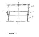
- Figure 2 is the illustration of the structure of sealing connection device.
- Figure 3 is the illustration of the structure of sealing device at the seed shaft.
- Figure 4 is the illustration of the structure of sealing device at the crucible-transmitting shaft.
- Figure 5 is the illustration of the structure of seed shaft.
- the VCZ single crystal growth apparatus is shown in Figure 1 .
- the numeral 1 is denoted the outfit of the single crystal furnace, and the other portions of the furnace are not illustrated herein.
- a hot-wall sealed container 2 is mounted in the single crystal furnace 1 .
- the hot-wall sealed container 2 is formed of upper container part 3 and lower container part 4, and the upper and lower container parts are connected through a sealing connection device 5.
- the hot-wall sealed container 2 surrounds a crucible 6, and the crucible 6 is installed on a crucible-transmitting shaft 7. Above the crucible is a seed shaft 8. And the seed shaft 8 and the crucible-transmitting shaft 7 is, respectively, inserted into the hot-wall sealed container through sealing devices 9 and 10.
- the sealing connection device 5 comprises an annular groove 11, and the structure thereof is shown in Figure 2 .
- the annular groove 11 and the lower container part 4 are integrated.
- the end of the upper container part 3 fits within the annular groove 11 , and the annular groove 11 is filled with boron oxide.
- the sealing devices 9 and 10 are formed of a sealing chamber 13 and a sealing ring 14, and the structure thereof is illustrated in Figures 3 and 4 .
- Inside of the sealing chamber 13 is an annular groove 15, and the bottom of the sealing chamber is of a central hole 16.
- the sealing ring 14 has a groove 17.
- the peripheral surface of the sealing ring 14 fits tightly with the inner surface of the annular groove 15 of the sealing chamber 13.
- the groove 17 of the sealing ring 14 and the annular groove 15 of the sealing chamber 13 face each other to form a liquid storage chamber 18.
- the opening of the sealing ring 14 and the upper edge of the central hole 16 form an interval 19 which is the entry of the liquid storage chamber 18.
- the height of the sealing ring 14 is less than that of the annular groove 15 in the sealing chamber 13.
- the annular groove 15 of the sealing chamber 13 is filled with boron oxide. Beneath the sealing device 10, a connection accepter 20 is affixed on the crucible-transmitting shaft 7 and has its upwards opening .
- the seed shaft 8 is formed of an upper seed shaft 21 and a lower seed shaft 22.
- the upper seed shaft is solid and the lower seed shaft is a hollow rod.
- the end of the upper seed shaft 21 has a connecting shank 23, and an annular slot 24 is in the middle of the connecting shank 23 carved .
- the lower edge of the opening of the annular slot 24 is tempered with conic slant 25.
- the connecting shank 23 and a connecting hole 26 of the top of the lower seed shaft 22 fit tightly with each other, and a pin 27 is inserted through the connecting shank 23 and connecting hole 26 to fix them together.
- the end of the lower seed shaft 22 has a seed installation hole 28, in which a seed crystal 29 may be mounted, and a locking pin 30 is used to fix the seed crystal 29 therein.
- the upper and lower seed shafts are made of ceramic material.
- the compound raw materials will be put into the crucible 6.
- Gallium and Arsenic are put into the crucible 6.
- the Gallium and Arsenic are heated, and at the same time the boron oxide in the sealing connection device 5, and in the sealing devices 9 and 10 is heated, too.
- the boron oxide is melted to form a liquid sealing, a very well sealed space is formed in the hot-wall sealed container 2. In this sealed space, the control of Arsenic vapor pressure can be maintained so that the ratio of the Arsenic to Gallium may meet the prescribed requirement, and the decomposition loss of the compound may be prevented.
- the temperature gradient of crystal is small when this growth method is used.
- the quality of the crystal will be increased, while the dislocation density of the single crystal will be decreased.
- the deformation of the seed shaft used in this apparatus is small and the sealing is good.
- the central alignment is good and there is little vibration during rotation so as to benefit the growth of the crystal.
- the hot-wall sealed container 2 can be open right away to take the crystal out. Then the hot-wall sealed container 2 may be reused. The operation is quite simple.
Landscapes
- Chemical & Material Sciences (AREA)
- Engineering & Computer Science (AREA)
- Crystallography & Structural Chemistry (AREA)
- Materials Engineering (AREA)
- Metallurgy (AREA)
- Organic Chemistry (AREA)
- Inorganic Chemistry (AREA)
- Crystals, And After-Treatments Of Crystals (AREA)
- Liquid Deposition Of Substances Of Which Semiconductor Devices Are Composed (AREA)
Description
- The present invention relates to semiconductor crystal growing equipments. More particularly, it relates to a vapor controlled czochralski (VCZ) single crystal growth apparatus.
- In a conventional single crystal furnace for producing compound semiconductor crystals, a hot-wall sealed container is provided outside of the crucible in order to prevent decomposition loss of the compound and to assure a proper stoichiometry of the compound single crystal. This will not result in coagulation of the mixed steam evaporated from the crucible (primarily the steam of elements with high decomposition pressure) and form the mixed vapor in the container. The other hot-wall sealed containers are integral and not easy to assemble. They cannot be opened when they are hot, and cannot be used repeatedly. Therefore, they are not convenient to operate, and it increase the manufacture cost.
- The object of the present invention is to provide a czochralski single crystal growth apparatus with vapor pressure control, wherein the hot-wall sealed container can be opened when it is still hot, and can be used repeatedly. Thus, it is convenient for installation and has better sealing property. It is easy to control the vapor pressure therein.
- European Patent Application No.
0 139 157 and European Patent Application No.0 355 746 disclose a vapour controlled Czochralski apparatus having a two-part chamber sealably and seperably connected to each other along the periphery of a side-wall. The chamber is arranged in a single crystal furnace. Liquid seals are utilized between each part of the chamber.EP 0 139 157 additionally discloses a liquid seal between the chamber and each of the crucible transmitting shaft and the seed shaft. - A VCZ single crystal growth apparatus of the present invention comprises a single crystal furnace, a heating unit, mechanical transmission unit and gaseous adjustment unit. In the single crystal furnace, mounted is a hot-wall sealed container. The hot-wall sealed container comprises an upper part and a lower part, and a sealing connection device between the upper and lower parts of the container. Within the hot-wall sealed container mounted is a crucible, and a crucible-transmitting shaft and a seed crystal shaft is embedded in the hot-wall sealed container through respective sealing devices.
- The sealing connection device of the container includes an annular groove. The annular groove integrates with the top of the lower part of container, and the end of the upper part of container fits within the annular groove. At the top of the hot-wall sealed container, there is an observation window.
- The sealing device of the crucible-transmitting shaft and the seed crystal shaft consists of sealing chamber and sealing ring. The sealing chamber has a central hole at its bottom. An annular groove is formed between the sealing chamber and either of the crucible-transmitting shaft and the seed shaft. The sealing ring has a groove, and the sealing ring is affixed within the annular groove of the sealing chamber so that the outer peripheral surface is fitted tightly with the inner surface of the sealing chamber. The sealing ring and the the sealing chamber are disposed to form a liquid storage chamber therebetween. An interval exists between the groove of sealing ring and the upper edge of the central hole of the sealing chamber. The height of the sealing ring is smaller than the height of the annular groove of the sealing chamber.
- The crucible-transmitting shaft passes through the lower end of the sealing device, a connection accepter which faces to the sealing chamber is affixed on the crucible-transmitting shaft. The sealing chamber and the sealing ring can be integrated, which includes a liquid storage chamber. The height of the sealing ring is one third to two third of the height of the annular groove of the sealing chamber.
- The seed shaft is comprised of upper and lower seed shafts. The upper seed crystal shaft is solid rod while the lower seed crystal shaft is a hollow rod. The end of the upper seed shaft has a connecting shank that first tightly with the connecting hole of the top of the lower seed crystal shaft, and a pin passes through the connecting shank and connecting hole. The end of the lower seed crystal shaft has a seed installation hole on which is a site pinhole. The connecting shank is carved with an annular groove, and the lower edge of the annular groove is tempered with conic slant.
- This VCZ single crystal growth apparatus of the present invention has the following advantages:
- 1. The hot-wall sealed container of the apparatus has simple structure, and is easy to assemble. It can be opened when it is hot and can be used repeatedly. The hot-wall sealed container is divided into upper and lower container parts, and has a sealing connection device therebetween. An annular groove is used to seal the sealing connection device, and boron oxide is filled into the groove. At high temperature, boron oxide is melted and thus surrounds the end of the upper container part to form liquid seal. This seal has simple structure and is better in performance, and easy to install. The container can be opened when it is hot, and will not cause any damage to the upper and lower container parts. Thus, such a hot-wall sealed container may be used repeatedly. It may even reduce the operation and manufacture cost.
- 2. Because the seal of the hot-wall sealed container of the apparatus is good, it is easy to control the vapor pressure within the hot-wall sealed container. The sealing between the hot-wall sealed container and the seed shaft and the crucible-transmitting shaft also utilizes the sealing of the liquid boron oxide. The liquid boron oxide, after being melt, sticks on the seed shaft and the crucible-transmitting shaft such that it fills all intervals between the sealing device and the seed shaft or crucible-transmitting shaft. This prevents the mixed vapor in the hot-wall sealed container from leaking, maintains the desired vapor pressure, and facilitates the control adjustment of the vapor pressure in the hot-wall sealed container.
- 3. The size of the seed shaft becomes smaller, but it is better centered and has better seal. It vibrates less when it rotates so that the crystal grows better. The lower part of the seed shaft is a hollow rod with thin wall such that it deforms less when being heated. Therefore, it can be properly conjugated with the sealing device of the hot-wall sealed container to ensure the better sealing of the sealing devices. The upper and lower parts of seed shafts are fitted tightly. It can prevent the vapor in the hot-wall sealed container from leaking through the connection. The connection surfaces of the upper and lower seed shaft are accurately machined to have a precise size such that they are well centered and do not vibrate during the rotation. This benefits the crystal growth. If the seed shaft is made of ceramic material, it has better erosion resistance, and may be used longer and reduce the secondary pollution.
- 4. It is convenient to adjust the vapor pressure in the hot-wall sealed container, and benefits to the adjustment of the stoichiometry of the single crystal.
- 5. This apparatus is mainly suitable for growing GaAs, InAs and GaP crystal. The quality of this crystal is good, and the dislocation density is low. For instance, the dislocation density of the
Φ 3" semi-insulating GaAs single crystal may be 7000 cm-2 to 9000 cm-2, and the dislocation density of theΦ 4" semi-insulation arsenic gallium single crystal may reach 3.5 x 104 cm-2 to 4.2 x 104 cm-2. -
Figure 1 is an illustration of structure of the VCZ crystal growing apparatus. -
Figure 2 is the illustration of the structure of sealing connection device. -
Figure 3 is the illustration of the structure of sealing device at the seed shaft. -
Figure 4 is the illustration of the structure of sealing device at the crucible-transmitting shaft. -
Figure 5 is the illustration of the structure of seed shaft. - The apparatus of the present invention is described in details hereinafter in connection with the accompanying drawings.
- The VCZ single crystal growth apparatus is shown in
Figure 1 . InFig. 1 , the numeral 1 is denoted the outfit of the single crystal furnace, and the other portions of the furnace are not illustrated herein. In the single crystal furnace 1, a hot-wall sealedcontainer 2 is mounted. The hot-wall sealedcontainer 2 is formed ofupper container part 3 andlower container part 4, and the upper and lower container parts are connected through asealing connection device 5. The hot-wall sealedcontainer 2 surrounds acrucible 6, and thecrucible 6 is installed on a crucible-transmittingshaft 7. Above the crucible is aseed shaft 8. And theseed shaft 8 and the crucible-transmittingshaft 7 is, respectively, inserted into the hot-wall sealed container through sealingdevices - The
sealing connection device 5 comprises an annular groove 11, and the structure thereof is shown inFigure 2 . The annular groove 11 and thelower container part 4 are integrated. The end of theupper container part 3 fits within the annular groove 11, and the annular groove 11 is filled with boron oxide. On top of the hot-wall sealedcontainer 2, there is anobservation window 12. - The
sealing devices chamber 13 and a sealingring 14, and the structure thereof is illustrated inFigures 3 and4 . Inside of the sealingchamber 13 is anannular groove 15, and the bottom of the sealing chamber is of acentral hole 16. The sealingring 14 has agroove 17. The peripheral surface of the sealingring 14 fits tightly with the inner surface of theannular groove 15 of the sealingchamber 13. Thegroove 17 of the sealingring 14 and theannular groove 15 of the sealingchamber 13 face each other to form aliquid storage chamber 18. The opening of the sealingring 14 and the upper edge of thecentral hole 16 form aninterval 19 which is the entry of theliquid storage chamber 18. The height of the sealingring 14 is less than that of theannular groove 15 in the sealingchamber 13. Theannular groove 15 of the sealingchamber 13 is filled with boron oxide. Beneath the sealingdevice 10, aconnection accepter 20 is affixed on the crucible-transmittingshaft 7 and has its upwards opening . - As illustrated in
Figure 5 , theseed shaft 8 is formed of anupper seed shaft 21 and alower seed shaft 22. The upper seed shaft is solid and the lower seed shaft is a hollow rod. The end of theupper seed shaft 21 has a connecting shank 23, and anannular slot 24 is in the middle of the connecting shank 23 carved . The lower edge of the opening of theannular slot 24 is tempered withconic slant 25. The connecting shank 23 and a connectinghole 26 of the top of thelower seed shaft 22 fit tightly with each other, and apin 27 is inserted through the connecting shank 23 and connectinghole 26 to fix them together. The end of thelower seed shaft 22 has aseed installation hole 28, in which aseed crystal 29 may be mounted, and alocking pin 30 is used to fix theseed crystal 29 therein. The upper and lower seed shafts are made of ceramic material. - During the operation of the VCZ single crystal growth apparatus, the compound raw materials will be put into the
crucible 6. For instance, when pulling GaAs crystal, Gallium and Arsenic are put into thecrucible 6. After connecting the upper and lower container parts, the Gallium and Arsenic are heated, and at the same time the boron oxide in thesealing connection device 5, and in thesealing devices container 2. In this sealed space, the control of Arsenic vapor pressure can be maintained so that the ratio of the Arsenic to Gallium may meet the prescribed requirement, and the decomposition loss of the compound may be prevented. In addition, the temperature gradient of crystal is small when this growth method is used. The quality of the crystal will be increased, while the dislocation density of the single crystal will be decreased. Moreover, the deformation of the seed shaft used in this apparatus is small and the sealing is good. And the central alignment is good and there is little vibration during rotation so as to benefit the growth of the crystal. The crystal growth finished, the hot-wall sealedcontainer 2 can be open right away to take the crystal out. Then the hot-wall sealedcontainer 2 may be reused. The operation is quite simple.
Claims (9)
- A VCZ single crystal growth apparatus comprising a single crystal furnace (1), a heating unit, a mechanical transmission unit, a gaseous adjustment unit, a hot-wall sealed container (2) mounted in the single crystal furnace, a crucible (6) mounted within the hot-sealed container (2), and a crucible-transmitting shaft (7) and a.seed shaft (8) inserted into the hot-wall sealed container (2) through respective sealing devices (9), wherein said hot-walled sealed container (2) includes an upper container part (3) and a lower container part (4), and a sealing connection device (5) is provided between the upper and lower container parts (3,4), characterized in that each of said sealing devices (9, 10), through which the crucible-transmitting shaft (7) and the seed shaft (8) pass respectively, is formed of a sealing chamber (13) and a sealing ring (14), and the sealing chamber (13) has a central hole (16) at the bottom, through which the crucible-transmitting shaft (7) and the seed shaft (8) pass, wherein an annular groove (15) is formed between the sealing chamber (13) and the crucible-transmitting shaft (7) and the seed shaft (8), and wherein a liquid storage chamber (18) is defined by a groove (17) in said sealing ring (14) and the annular groove (15) of said sealing chamber (13), with the outer peripheral surface of the sealing ring (14) fitting tightly between the inner surface of the sealing chamber (13) and the respective seed shaft (8), and crucible-transmitting shaft (7).
- The VCZ single crystal growth apparatus as set forth in Claim 1, characterized in that said sealing connection device (5) of the container (2) is formed of an annular groove (11), that integrates with the top of the lower container part (4), and the lower end of the upper part (3) of container fits within the annular groove (11).
- The VCZ single crystal growth apparatus as set forth in Claim 1 or 2, characterized in that there is an observation window (12) provided at the top of the hot-wall sealed container (2).
- The VCZ single crystal growth apparatus as set forth in Claim 1, characterized in that an interval (19) exists between the ring opening of the sealing ring (14) and the upper edge of the central hole (16) of the sealing chamber (13), and the height of the sealing ring (14) is smaller than the height of the annular groove (15) of the sealing chamber (13).
- The VCZ single crystal growth apparatus as set forth in Claim 4, characterized in that the height of the sealing ring is one third or two third of that of the annular groove (15) of the sealing chamber (13).
- The VCZ single crystal growth apparatus as set forth in Claim 1, characterized in that the crucible-transmitting shaft (7) passes through the lower end of the sealing device (9), and on the crucible-transmitting shaft (7) affixed is a connection accepter (20) facing the same direction of the sealing chamber (13).
- The VCZ single crystal growth apparatus as set forth in Claim 1, characterized in that the sealing chamber (13) and the sealing ring (14) are integrated to form the liquid storage chamber (18).
- The VCZ single crystal growth apparatus as set forth in Claim 1, characterized in that the seed shaft (8) is formed of upper and lower seed shafts, and the upper seed shaft (21) is solid rod, while the lower seed shaft (22) is hollow, and wherein lower end of the upper seed shaft (21) has a connecting shank (23) that fits tightly with a connecting hole (26) of the top of the lower seed shaft (22), and a pin (27) passes through the connecting shank (23) and the connecting hole (26), and wherein the lower end of the lower seed shaft has a seed crystal installation hole (28), on which is a site pinhole.
- The VCZ single crystal growth apparatus as set forth in Claim 8, characterized in that the connecting shank (23) is carved with an annular slot (24), and the lower edge of the annular slot (24) is tempered with the conic slant (25).
Applications Claiming Priority (2)
| Application Number | Priority Date | Filing Date | Title |
|---|---|---|---|
| CN01219206 | 2001-04-06 | ||
| CN01219206.6U CN2470372Y (en) | 2001-04-06 | 2001-04-06 | Straight-drawing crystal grower controlled by steam pressure |
Publications (2)
| Publication Number | Publication Date |
|---|---|
| EP1247882A1 EP1247882A1 (en) | 2002-10-09 |
| EP1247882B1 true EP1247882B1 (en) | 2013-11-20 |
Family
ID=4693010
Family Applications (1)
| Application Number | Title | Priority Date | Filing Date |
|---|---|---|---|
| EP01125551.0A Expired - Lifetime EP1247882B1 (en) | 2001-04-06 | 2001-10-25 | Vapor controlled czochralski (VCZ) single crystal growth apparatus |
Country Status (4)
| Country | Link |
|---|---|
| US (1) | US6720509B2 (en) |
| EP (1) | EP1247882B1 (en) |
| JP (1) | JP3803280B2 (en) |
| CN (1) | CN2470372Y (en) |
Families Citing this family (6)
| Publication number | Priority date | Publication date | Assignee | Title |
|---|---|---|---|---|
| US6942733B2 (en) * | 2003-06-19 | 2005-09-13 | Memc Electronics Materials, Inc. | Fluid sealing system for a crystal puller |
| CN102607923B (en) * | 2012-04-11 | 2014-04-09 | 中国科学院半导体研究所 | Silicon carbide material corrosion furnace |
| CN102628180A (en) * | 2012-04-23 | 2012-08-08 | 南京金美镓业有限公司 | Preparation method of high-purity indium phosphide polycrystalline rod |
| CN102776558B (en) * | 2012-07-30 | 2015-08-26 | 新疆天科合达蓝光半导体有限公司 | A kind of seed rod lift steady arm |
| CN107684795A (en) * | 2016-08-03 | 2018-02-13 | 隆基绿能科技股份有限公司 | Tail gas filter and vacuum system of single-crystal furnace |
| CN113913920B (en) * | 2021-10-18 | 2024-05-03 | 北京工业大学 | AlGaAs single crystal preparation method and preparation device |
Family Cites Families (7)
| Publication number | Priority date | Publication date | Assignee | Title |
|---|---|---|---|---|
| DE3466785D1 (en) * | 1983-08-06 | 1987-11-19 | Sumitomo Electric Industries | Apparatus for the growth of single crystals |
| EP0139157B1 (en) * | 1983-08-31 | 1988-07-06 | Research Development Corporation of Japan | Apparatus for growing single crystals of dissociative compounds |
| JPH01108195A (en) * | 1987-10-19 | 1989-04-25 | Sumitomo Electric Ind Ltd | Compound crystal pulling device |
| DE68917052T2 (en) * | 1988-08-19 | 1994-12-22 | Mitsubishi Materials Corp | Process for single crystal growth of decomposable semiconductor compounds. |
| DE4123337A1 (en) * | 1991-07-15 | 1993-01-21 | Leybold Ag | CRYSTAL DRAWING DEVICE |
| EP0559921B1 (en) * | 1991-09-19 | 2000-02-09 | Japan Science and Technology Corporation | Apparatus for and method of producing single crystal semiconductor of high dissociation pressure compound |
| US6358314B1 (en) * | 1996-01-25 | 2002-03-19 | Spx Corporation | Czochralski crystal growth system with an independently supported pull head |
-
2001
- 2001-04-06 CN CN01219206.6U patent/CN2470372Y/en not_active Expired - Lifetime
- 2001-10-25 JP JP2001328379A patent/JP3803280B2/en not_active Expired - Lifetime
- 2001-10-25 EP EP01125551.0A patent/EP1247882B1/en not_active Expired - Lifetime
- 2001-10-26 US US10/015,068 patent/US6720509B2/en not_active Expired - Lifetime
Also Published As
| Publication number | Publication date |
|---|---|
| JP2002308693A (en) | 2002-10-23 |
| EP1247882A1 (en) | 2002-10-09 |
| CN2470372Y (en) | 2002-01-09 |
| US6720509B2 (en) | 2004-04-13 |
| US20020144648A1 (en) | 2002-10-10 |
| JP3803280B2 (en) | 2006-08-02 |
Similar Documents
| Publication | Publication Date | Title |
|---|---|---|
| US6720509B2 (en) | Vapor controlled czochralski (VCZ) single crystal growth apparatus | |
| CN102220628A (en) | Device for growing semiconductor crystals | |
| CN118854440B (en) | Off-axis crystal growth device | |
| US4664742A (en) | Method for growing single crystals of dissociative compounds | |
| JPS63144187A (en) | Method and apparatus for growing dendritic web crystal of silicon | |
| CA1317202C (en) | Method of drawing-up a single crystal using a double-crucible apparatus and double-crucible apparatus therefor | |
| JPH0314800B2 (en) | ||
| US6358315B1 (en) | Method and apparatus for producing monocrystals | |
| JPH0142919B2 (en) | ||
| US5458083A (en) | Growth method for a rod form of single oxide crystal | |
| JPS60176995A (en) | Single crystal manufacturing method | |
| JPS644998B2 (en) | ||
| JPH03237088A (en) | Method for growing single crystal | |
| JP2546746Y2 (en) | Vertical Bridgman crucible | |
| JPS63274691A (en) | Single crystal growth method and equipment | |
| JP3551607B2 (en) | Method for producing GaAs single crystal | |
| JP3412376B2 (en) | Single crystal pulling device | |
| JPH03247582A (en) | Production device of compound semiconductor crystal | |
| JPS6041037B2 (en) | Manufacturing equipment for high dissociation pressure compound single crystal for semiconductors | |
| JP2719672B2 (en) | Single crystal growth method | |
| JP4100812B2 (en) | GaAs single crystal and manufacturing method thereof | |
| JP2781856B2 (en) | Method for manufacturing compound semiconductor single crystal | |
| JPS61275186A (en) | Single crystal pulling device | |
| JPH0131479B2 (en) | ||
| JP2985360B2 (en) | Single crystal manufacturing equipment |
Legal Events
| Date | Code | Title | Description |
|---|---|---|---|
| PUAI | Public reference made under article 153(3) epc to a published international application that has entered the european phase |
Free format text: ORIGINAL CODE: 0009012 |
|
| AK | Designated contracting states |
Kind code of ref document: A1 Designated state(s): AT BE CH CY DE DK ES FI FR GB GR IE IT LI LU MC NL PT SE TR |
|
| AX | Request for extension of the european patent |
Free format text: AL;LT;LV;MK;RO;SI |
|
| 17P | Request for examination filed |
Effective date: 20021014 |
|
| AKX | Designation fees paid |
Designated state(s): DE FR GB |
|
| GRAP | Despatch of communication of intention to grant a patent |
Free format text: ORIGINAL CODE: EPIDOSNIGR1 |
|
| INTG | Intention to grant announced |
Effective date: 20130705 |
|
| GRAS | Grant fee paid |
Free format text: ORIGINAL CODE: EPIDOSNIGR3 |
|
| GRAA | (expected) grant |
Free format text: ORIGINAL CODE: 0009210 |
|
| AK | Designated contracting states |
Kind code of ref document: B1 Designated state(s): DE FR GB |
|
| REG | Reference to a national code |
Ref country code: GB Ref legal event code: FG4D |
|
| REG | Reference to a national code |
Ref country code: DE Ref legal event code: R096 Ref document number: 60148448 Country of ref document: DE Effective date: 20140109 |
|
| REG | Reference to a national code |
Ref country code: DE Ref legal event code: R097 Ref document number: 60148448 Country of ref document: DE |
|
| PLBE | No opposition filed within time limit |
Free format text: ORIGINAL CODE: 0009261 |
|
| STAA | Information on the status of an ep patent application or granted ep patent |
Free format text: STATUS: NO OPPOSITION FILED WITHIN TIME LIMIT |
|
| 26N | No opposition filed |
Effective date: 20140821 |
|
| REG | Reference to a national code |
Ref country code: DE Ref legal event code: R097 Ref document number: 60148448 Country of ref document: DE Effective date: 20140821 |
|
| REG | Reference to a national code |
Ref country code: DE Ref legal event code: R119 Ref document number: 60148448 Country of ref document: DE |
|
| PG25 | Lapsed in a contracting state [announced via postgrant information from national office to epo] |
Ref country code: DE Free format text: LAPSE BECAUSE OF NON-PAYMENT OF DUE FEES Effective date: 20150501 |
|
| REG | Reference to a national code |
Ref country code: FR Ref legal event code: ST Effective date: 20150630 |
|
| PG25 | Lapsed in a contracting state [announced via postgrant information from national office to epo] |
Ref country code: FR Free format text: LAPSE BECAUSE OF NON-PAYMENT OF DUE FEES Effective date: 20141031 |
|
| PGFP | Annual fee paid to national office [announced via postgrant information from national office to epo] |
Ref country code: GB Payment date: 20201014 Year of fee payment: 20 |
|
| REG | Reference to a national code |
Ref country code: GB Ref legal event code: PE20 Expiry date: 20211024 |
|
| PG25 | Lapsed in a contracting state [announced via postgrant information from national office to epo] |
Ref country code: GB Free format text: LAPSE BECAUSE OF EXPIRATION OF PROTECTION Effective date: 20211024 |