EP1247654B1 - Method for calibrating a thermal printer - Google Patents
Method for calibrating a thermal printer Download PDFInfo
- Publication number
- EP1247654B1 EP1247654B1 EP20010000107 EP01000107A EP1247654B1 EP 1247654 B1 EP1247654 B1 EP 1247654B1 EP 20010000107 EP20010000107 EP 20010000107 EP 01000107 A EP01000107 A EP 01000107A EP 1247654 B1 EP1247654 B1 EP 1247654B1
- Authority
- EP
- European Patent Office
- Prior art keywords
- data
- density
- thermal head
- printer
- dwant
- Prior art date
- Legal status (The legal status is an assumption and is not a legal conclusion. Google has not performed a legal analysis and makes no representation as to the accuracy of the status listed.)
- Expired - Lifetime
Links
Images

Classifications
-
- B—PERFORMING OPERATIONS; TRANSPORTING
- B41—PRINTING; LINING MACHINES; TYPEWRITERS; STAMPS
- B41J—TYPEWRITERS; SELECTIVE PRINTING MECHANISMS, i.e. MECHANISMS PRINTING OTHERWISE THAN FROM A FORME; CORRECTION OF TYPOGRAPHICAL ERRORS
- B41J2/00—Typewriters or selective printing mechanisms characterised by the printing or marking process for which they are designed
- B41J2/315—Typewriters or selective printing mechanisms characterised by the printing or marking process for which they are designed characterised by selective application of heat to a heat sensitive printing or impression-transfer material
- B41J2/32—Typewriters or selective printing mechanisms characterised by the printing or marking process for which they are designed characterised by selective application of heat to a heat sensitive printing or impression-transfer material using thermal heads
- B41J2/35—Typewriters or selective printing mechanisms characterised by the printing or marking process for which they are designed characterised by selective application of heat to a heat sensitive printing or impression-transfer material using thermal heads providing current or voltage to the thermal head
- B41J2/355—Control circuits for heating-element selection
- B41J2/36—Print density control
-
- B—PERFORMING OPERATIONS; TRANSPORTING
- B41—PRINTING; LINING MACHINES; TYPEWRITERS; STAMPS
- B41J—TYPEWRITERS; SELECTIVE PRINTING MECHANISMS, i.e. MECHANISMS PRINTING OTHERWISE THAN FROM A FORME; CORRECTION OF TYPOGRAPHICAL ERRORS
- B41J29/00—Details of, or accessories for, typewriters or selective printing mechanisms not otherwise provided for
- B41J29/38—Drives, motors, controls or automatic cut-off devices for the entire printing mechanism
- B41J29/393—Devices for controlling or analysing the entire machine ; Controlling or analysing mechanical parameters involving printing of test patterns
Definitions
- the present invention relates to a method for applying thermal energy to a recording medium, using a thermal head having energisable heating elements which are individually addressable. More specifically the invention concerns a method for calibrating a continuous tone thermal printer.
- the recording medium is a thermographic material, and the method for thermal printing relates to thermography.
- Thermal imaging or thermography is a recording process wherein images are generated by the use of imagewise modulated thermal energy.
- Thermography is concerned with materials which are not photosensitive, but are sensitive to heat or thermosensitive and wherein imagewise applied heat is sufficient to bring about a visible change in a thermosensitive imaging material, by a chemical or a physical process which changes the optical density.
- thermographic recording materials are of the chemical type. On heating to a certain conversion temperature, an irreversible chemical reaction takes place and a coloured image is produced.
- the heating of the thermographic recording material may be originating from image signals which are converted to electric pulses and then through a driver circuit selectively transferred to a thermal print head.
- the thermal print head consists of microscopic heat resistor elements, which convert the electrical energy into heat via the Joule effect.
- the electric pulses thus converted into thermal signals manifest themselves as heat transferred to the surface of the thermographic material, e.g. paper, wherein the chemical reaction resulting in colour development takes place.
- This principle is described in "Handbook of Imaging Materials” (edited by Arthur S. Diamond - Diamond Research Corporation - Ventura, California, printed by Marcel Dekker, Inc. 270 Madison Avenue, New York, ed. 1991, p. 498-499).
- a particular interesting direct thermal imaging element uses an organic silver salt in combination with a reducing agent. An image can be obtained with such a material because under influence of heat the silver salt is developed to metallic silver.
- a thermal printer varies the printing energy to control the density of the thermal print.
- the objective is to print predictable densities with minimum increments to produce a nearly continuous grey scale over the desired density range.
- control is a two stage process.
- a traditional technique for calibrating a thermal printer is as follows. First, a first calibration page is printed with a limit setting to produce the desired maximum density and a full range of print settings. The next step is to determine whether this is the desired limit setting by visually inspecting the printed page. The normal objective is to find the minimum exposure required to print the full range of desired densities. The lower the limit setting, the more nearly continuous the grey scale in the printed film. The process of printing and adjusting the maximum limit setting is repeated until a desired limit setting is determined.
- a second calibration page is printed with the limit system setting selected and with a subset of print system settings which cover the full range of print settings.
- the resulting densities of the printed page are then measured and a print setting to density table created for the full range of print settings.
- An output lookup table that can be used to set exposure to produce the desired density for any digital image value is created using the print setting to density table.
- the thermal printer prints pages with this output lookup table to produce the desired densities while the same maximum exposure is appropriate. However, if maximum exposure is changed the calibration process must be repeated.
- EP 453 714 the amount of energy fed to the printing elements for a certain gradation number can be changed to adapt to variable characteristics of different recording materials. This is based upon test prints to map the input data to the matching signal send to each heating element of the printing head.
- a problem which arises with this calibration technique is that calibration data is specific to a particular limit control setting. If that setting needs to be changed the entire process of successive prints to find the desired limit control setting for maximum density and calibration must be repeated. Also, if different users want different maximum densities each requires separate calibration. Such repeated calibrations is inefficient, costly and non-productive.
- an index "i” is used in relation to certain data (e.g. printer data P i , a density Di, thermal head data TH i , rescaled thermal head data Th i ' , etc), whereas an index "j" is used to indicate a user-related variable (e.g. Prefnew j , a desired density Dwant j , etc).
- a combination of both indexes is applicable (e.g. a density D ji ).
- Such combined index "ji” is simplified to a single index "i", although people skilled in the art may very well understand that implicitly a combined index "ji” is understood.
- figure 1 shows a preferred embodiment of a calibration method according to the present invention
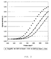
- figure 2 is a diagram showing experimentally measured densities and finally obtained densities in relation to printer data.
- a so called “slicing” and a so called “duty cycle” are explained in full depth e.g. in EPA-01000003.2 (in the name of Agfa-Gevaert); an example of a "user taste” (in this drawing indicated by the abbreviation "U”) is explained e.g.
- reference printing power Pref means the power dissipated under reference conditions comprising V TH , Rref and Dcref, and more particularly the time-averaged power dissipated during a 100% time slice.
- a method for calibrating a thermal printer comprising a thermal head incorporating a plurality of energisable heating elements, comprises the steps of:
- the invention can be rephrased as a method for calibrating a thermal printer comprising a thermal head incorporating a plurality of energisable heating elements, said method comprising the steps of:
- a method for calibrating a thermal printer comprising a thermal head incorporating a plurality of energisable heating elements, said method comprising the steps of:
- a method for calibrating a thermal printer comprising a thermal head incorporating a plurality of energisable heating elements, said method comprises the steps of:
- said steps of supplying, printing a calibration pattern, and measuring a density Dexp i for each patch of said density wedge are replaced by capturing a new value for a desired density Dwant j .
- said step of printing a calibration pattern is preceded by the steps
- a method further comprises the step of searching two consecutive values of thermal head data TH k and TH l which correspond with densities D k and D l wherein between a desired density Dwant j is enclosed.
- N a bitdepth (representing a number of bits)of said thermal head data TH
- M is a bitdepth (representing a number of bits) of said printer data P i
- M is different from N, preferably N > M.
- M 10 or 12
- N 13.
- thermographic material comprises on a support a thermosensitive layer incorporating an organic silver salt and a reducing agent contained in said thermosensitive layer and/or in another optional layer.
- An apparatus for thermal recording an image on a thermographic material can use a method as described hereabove.
- said output values Dh k , Dh kcm and Dh kcml relate to values of an optical density and/or to values of a pixel size to be reproduced on said thermographic material m.
- a 27 step calibration wedge was printed at a reference printing power Pref of 75.6 mW.
- the 27 printer data values P1, P2, ... P27 lay between 411 and 1023.
- the 27 corresponding experimental density values lay between 0.23 and 3.49.
- the 27 printer data values P1, P2, ..., P27 were transformed to 27 thermal head data values TH1, TH2, ... , TH27.
- the rescaled P-values (indicated by the symbol P') were calculated and the output lookup table that is used during printing to set the appropriate energy to produce the desired density for any digital image value was created.
- Thermal imaging according to the present invention can be used for production of both transparencies and reflection-type prints.
- thermographic recording materials based on an opaque (e.g. white) base are used, whereas in the medical diagnostic field monochrome (e.g. black) images on a transparent base find wide application, since such prints can conveniently be viewed by means of a light box.
- monochrome e.g. black
- the method of the present invention is applicable for a wide variety of printing techniques.
- the method may be directed towards representing an image of a human body obtained during medical imaging and to a printing of medical image picture data received from a medical imaging device, e.g. a medical image camera.
- a medical imaging device e.g. a medical image camera.
- NDT non-destructive Testing
- exemplary purposes of NDT comprise inspection or quality control of materials, welded joints or assemblies; development of manufacturing processes; experimenting in research; etc.
- the image data may be graphical image picture data received e.g. from a computerised publishing system.
- a method according to the present invention also may be applied in graphic plotters, in chart recorders, in computer printers, etc.
- said densities relate to values of an optical density and/or to values of a pixel size to be reproduced on said thermographic material m.
- a so-called heating element may comprise e.g. a resistive heating element, an inductive heating element, a pyrotechnic heating element, or a high frequency heating element.
Landscapes
- Electronic Switches (AREA)
Priority Applications (4)
| Application Number | Priority Date | Filing Date | Title |
|---|---|---|---|
| EP20010000107 EP1247654B1 (en) | 2001-04-05 | 2001-04-05 | Method for calibrating a thermal printer |
| DE2001621421 DE60121421T2 (de) | 2001-04-05 | 2001-04-05 | Verfahren zur Eichung eines Thermodruckers |
| JP2002099727A JP2002331699A (ja) | 2001-04-05 | 2002-04-02 | 感熱式プリンターの校正方法 |
| US10/116,363 US6774922B2 (en) | 2001-04-05 | 2002-04-04 | Method for calibrating a thermal printer |
Applications Claiming Priority (1)
| Application Number | Priority Date | Filing Date | Title |
|---|---|---|---|
| EP20010000107 EP1247654B1 (en) | 2001-04-05 | 2001-04-05 | Method for calibrating a thermal printer |
Publications (2)
| Publication Number | Publication Date |
|---|---|
| EP1247654A1 EP1247654A1 (en) | 2002-10-09 |
| EP1247654B1 true EP1247654B1 (en) | 2006-07-12 |
Family
ID=8176034
Family Applications (1)
| Application Number | Title | Priority Date | Filing Date |
|---|---|---|---|
| EP20010000107 Expired - Lifetime EP1247654B1 (en) | 2001-04-05 | 2001-04-05 | Method for calibrating a thermal printer |
Country Status (3)
| Country | Link |
|---|---|
| EP (1) | EP1247654B1 (enExample) |
| JP (1) | JP2002331699A (enExample) |
| DE (1) | DE60121421T2 (enExample) |
Families Citing this family (6)
| Publication number | Priority date | Publication date | Assignee | Title |
|---|---|---|---|---|
| EP1431045A1 (en) * | 2002-12-17 | 2004-06-23 | Agfa-Gevaert | A modeling method for taking into account thermal head and ambient temperature. |
| EP1457345B1 (en) * | 2003-03-12 | 2009-12-30 | Agfa HealthCare NV | Thermal head printer and process for printing substantially light-insensitve recording materials. |
| US7139010B2 (en) | 2003-03-12 | 2006-11-21 | Agfa Gevaert | Thermal head printer and process for printing substantially light-insensitive recording materials |
| JP2010100022A (ja) | 2008-10-27 | 2010-05-06 | Seiko Instruments Inc | 発熱抵抗素子部品 |
| JP2019084799A (ja) * | 2017-11-10 | 2019-06-06 | セイコーエプソン株式会社 | サーマルプリンター、サーマルプリンターの制御方法、及び、印刷システム |
| CN115635778B (zh) * | 2021-07-20 | 2025-03-14 | 珠海趣印科技有限公司 | 一种热敏打印机的全自动化性能测试方法及系统 |
Family Cites Families (7)
| Publication number | Priority date | Publication date | Assignee | Title |
|---|---|---|---|---|
| JPH0832462B2 (ja) * | 1990-02-27 | 1996-03-29 | 三菱電機株式会社 | 階調記録プリンタ |
| JP2974468B2 (ja) * | 1991-09-11 | 1999-11-10 | キヤノン株式会社 | 画像形成装置及び画像形成方法 |
| JPH06115152A (ja) * | 1992-10-07 | 1994-04-26 | Fuji Photo Film Co Ltd | 光感熱記録における濃度補正方法 |
| TW476746B (en) | 1997-07-23 | 2002-02-21 | Shell Int Research | Hydrogenolysis of glycerol |
| JPH11184190A (ja) * | 1997-12-24 | 1999-07-09 | Oki Data Corp | 電子写真式プリンタ |
| JP2001058423A (ja) * | 1999-08-19 | 2001-03-06 | Fuji Photo Film Co Ltd | 自動濃度調整機能付きプリンタ及びプリンタの濃度調整方法 |
| JP2001088328A (ja) * | 1999-09-22 | 2001-04-03 | Canon Inc | 記録方法および記録装置 |
-
2001
- 2001-04-05 EP EP20010000107 patent/EP1247654B1/en not_active Expired - Lifetime
- 2001-04-05 DE DE2001621421 patent/DE60121421T2/de not_active Expired - Lifetime
-
2002
- 2002-04-02 JP JP2002099727A patent/JP2002331699A/ja active Pending
Also Published As
| Publication number | Publication date |
|---|---|
| JP2002331699A (ja) | 2002-11-19 |
| DE60121421T2 (de) | 2007-01-11 |
| EP1247654A1 (en) | 2002-10-09 |
| DE60121421D1 (de) | 2006-08-24 |
Similar Documents
| Publication | Publication Date | Title |
|---|---|---|
| US6597385B2 (en) | Method for thermal printing | |
| KR920010609B1 (ko) | 계조프린터 | |
| JPH02121853A (ja) | サーマルヘッド制御回路 | |
| KR20070001245A (ko) | 열 반응 수정 시스템 | |
| EP0542012A1 (en) | Calibration method for video image reproduction with electronic printer and video monitor | |
| EP0577135A2 (en) | Printer utilizing temperature evaluation and temperature detection | |
| EP1247654B1 (en) | Method for calibrating a thermal printer | |
| JPH0632942B2 (ja) | 記録濃度制御装置 | |
| EP0596345B1 (en) | Laser printer calibration | |
| US6774922B2 (en) | Method for calibrating a thermal printer | |
| EP1655138A2 (en) | Thermal Printer | |
| EP0536822B1 (en) | Method for implementing specific transfer curves in thermal sublimation printers | |
| EP1234677B1 (en) | Method for thermal printing | |
| JP2695008B2 (ja) | 感熱記録装置 | |
| JPS62149463A (ja) | 階調制御方式 | |
| KR100743793B1 (ko) | 다계조표현 감열기록장치 | |
| JPH0584102B2 (enExample) | ||
| JPH01133758A (ja) | プリンタ装置 | |
| EP1582362B1 (en) | Thermal printing method | |
| De Langhe et al. | Direct thermal hard copy system for medical diagnostic applications | |
| Habbal et al. | Image presentation options for a distributed PACS environment | |
| JPS61130063A (ja) | サ−マルヘツド駆動装置 | |
| JPH082660B2 (ja) | 階調プリンタにおける温度別濃度特性補正テ−ブル作成方法 | |
| JPS6158764A (ja) | サーマルヘッドのパルス幅制御装置 | |
| JPH0419164A (ja) | 熱転写記録の印写濃度制御方法 |
Legal Events
| Date | Code | Title | Description |
|---|---|---|---|
| PUAI | Public reference made under article 153(3) epc to a published international application that has entered the european phase |
Free format text: ORIGINAL CODE: 0009012 |
|
| AK | Designated contracting states |
Kind code of ref document: A1 Designated state(s): AT BE CH CY DE DK ES FI FR GB GR IE IT LI LU MC NL PT SE TR |
|
| AX | Request for extension of the european patent |
Free format text: AL;LT;LV;MK;RO;SI |
|
| 17P | Request for examination filed |
Effective date: 20030409 |
|
| AKX | Designation fees paid |
Designated state(s): DE FR GB |
|
| 17Q | First examination report despatched |
Effective date: 20030710 |
|
| RIN1 | Information on inventor provided before grant (corrected) |
Inventor name: HERRMANN-BIBER,BARTHOLOMAUS Inventor name: KAERTS, ERIC |
|
| GRAP | Despatch of communication of intention to grant a patent |
Free format text: ORIGINAL CODE: EPIDOSNIGR1 |
|
| GRAS | Grant fee paid |
Free format text: ORIGINAL CODE: EPIDOSNIGR3 |
|
| GRAA | (expected) grant |
Free format text: ORIGINAL CODE: 0009210 |
|
| AK | Designated contracting states |
Kind code of ref document: B1 Designated state(s): DE FR GB |
|
| REG | Reference to a national code |
Ref country code: GB Ref legal event code: FG4D |
|
| REF | Corresponds to: |
Ref document number: 60121421 Country of ref document: DE Date of ref document: 20060824 Kind code of ref document: P |
|
| ET | Fr: translation filed | ||
| REG | Reference to a national code |
Ref country code: GB Ref legal event code: 732E |
|
| PLBE | No opposition filed within time limit |
Free format text: ORIGINAL CODE: 0009261 |
|
| STAA | Information on the status of an ep patent application or granted ep patent |
Free format text: STATUS: NO OPPOSITION FILED WITHIN TIME LIMIT |
|
| 26N | No opposition filed |
Effective date: 20070413 |
|
| REG | Reference to a national code |
Ref country code: FR Ref legal event code: TP |
|
| REG | Reference to a national code |
Ref country code: FR Ref legal event code: PLFP Year of fee payment: 16 |
|
| REG | Reference to a national code |
Ref country code: FR Ref legal event code: PLFP Year of fee payment: 17 |
|
| REG | Reference to a national code |
Ref country code: FR Ref legal event code: PLFP Year of fee payment: 18 |
|
| REG | Reference to a national code |
Ref country code: GB Ref legal event code: 732E Free format text: REGISTERED BETWEEN 20180816 AND 20180822 |
|
| REG | Reference to a national code |
Ref country code: DE Ref legal event code: R081 Ref document number: 60121421 Country of ref document: DE Owner name: AGFA NV, BE Free format text: FORMER OWNER: AGFA HEALTHCARE NV, MORTSEL, BE |
|
| PGFP | Annual fee paid to national office [announced via postgrant information from national office to epo] |
Ref country code: GB Payment date: 20200310 Year of fee payment: 20 |
|
| PGFP | Annual fee paid to national office [announced via postgrant information from national office to epo] |
Ref country code: FR Payment date: 20200310 Year of fee payment: 20 |
|
| PGFP | Annual fee paid to national office [announced via postgrant information from national office to epo] |
Ref country code: DE Payment date: 20200306 Year of fee payment: 20 |
|
| REG | Reference to a national code |
Ref country code: DE Ref legal event code: R071 Ref document number: 60121421 Country of ref document: DE |
|
| REG | Reference to a national code |
Ref country code: GB Ref legal event code: PE20 Expiry date: 20210404 |
|
| PG25 | Lapsed in a contracting state [announced via postgrant information from national office to epo] |
Ref country code: GB Free format text: LAPSE BECAUSE OF EXPIRATION OF PROTECTION Effective date: 20210404 |