EP1246703B1 - Anlage zum spritzen von beschichtungsmaterial - Google Patents
Anlage zum spritzen von beschichtungsmaterial Download PDFInfo
- Publication number
- EP1246703B1 EP1246703B1 EP01903910A EP01903910A EP1246703B1 EP 1246703 B1 EP1246703 B1 EP 1246703B1 EP 01903910 A EP01903910 A EP 01903910A EP 01903910 A EP01903910 A EP 01903910A EP 1246703 B1 EP1246703 B1 EP 1246703B1
- Authority
- EP
- European Patent Office
- Prior art keywords
- actuator
- valve
- installation according
- assembly
- product
- Prior art date
- Legal status (The legal status is an assumption and is not a legal conclusion. Google has not performed a legal analysis and makes no representation as to the accuracy of the status listed.)
- Expired - Lifetime
Links
Images


Classifications
-
- B—PERFORMING OPERATIONS; TRANSPORTING
- B05—SPRAYING OR ATOMISING IN GENERAL; APPLYING FLUENT MATERIALS TO SURFACES, IN GENERAL
- B05B—SPRAYING APPARATUS; ATOMISING APPARATUS; NOZZLES
- B05B12/00—Arrangements for controlling delivery; Arrangements for controlling the spray area
- B05B12/14—Arrangements for controlling delivery; Arrangements for controlling the spray area for supplying a selected one of a plurality of liquids or other fluent materials or several in selected proportions to a spray apparatus, e.g. to a single spray outlet
- B05B12/149—Arrangements for controlling delivery; Arrangements for controlling the spray area for supplying a selected one of a plurality of liquids or other fluent materials or several in selected proportions to a spray apparatus, e.g. to a single spray outlet characterised by colour change manifolds or valves therefor
Definitions
- the invention relates to a projection installation of coating product and, more specifically, to an installation including at least one projector capable of projecting selectively different products on objects to be coated.
- EP-A-0 274 322 discloses an installation in which a multi-axis robot carries a reservoir of product of coating connected to a projector and allowing its supply of product from connection means provided for a fixed position in a cabin.
- WO-A-99/52 644 discloses a method and a projection installation of coating product in which a cleaning-filling station of a tank, carried by a multi-axis robot and associated with a projector, is arranged in a cabin, this station including a connected product change block feeding circuits and tank carousel for less used shades.
- DE-A-42 14 779 discloses a manual change device of colors in which an alignment between a conduit downstream and several upstream ducts is obtained by rotating a tray. Controlled valves must be provided at a time upstream and downstream of this device, these valves to be Maneuvered manually or consisting of electro-valves whose cost price is important.
- the known systems therefore generally include a number of electro-valves or valves ordered important as well as many pneumatic hoses and fittings for these valves, which increases their cost price and makes more complex cleaning operations to the extent that these valves should be cleaned with the utmost care to to avoid a mixture of harmful coating products to a quality projection as required, in particular, in the field of motor vehicle construction.
- US-A-3,240,225 discloses a selection apparatus of painting in which arrivals of paint ducts are arranged in a circle, which imposes amplitude movements important to the connection device associated with them. This results in the compulsory use of flexible hoses relatively long, which must be purged and cleaned during each product change, hence a consumption relatively large amount of paint and solvent. In addition, the circular movements imposed on the moving parts are long, resulting in a relatively large minimum cycle time for a paint change operation.
- Another apparatus of this type is described in US-A-3,674,207, in which the duct arrivals are arranged along a right, and the downstream duct is arranged on a moving carriage on along the said right.
- the invention relates to an installation for projecting coating product comprising at least one projector and multiple power lines of this projector in coating product connected to a connection assembly, in which each downstream end of a line is equipped with a shut-off valve suitable for be controlled by an actuator piloted and arranged at the entrance of a projector supply duct, this actuator and this set being able to be moved one with respect to the other, so that the actuator can be arranged selectively opposite a downstream end of one of the lines feed and maneuver the valve from this line.
- This facility is characterized in that the ends of line are arranged in rows and columns while a together, including the actuator and connected to the conduit power supply, is mobile parallel to a flat face a plate where the ends of the line open.
- a single actuator is used to the selective connection of several supply lines with the projector and / or associated tank. It is therefore not no need to provide a large number of actuators, such as solenoid valves, as is the case in the case of systems of the prior art.
- the valves housed in the downstream ends of the feed lines are only ordered by the actuator only when it is correctly positioned relative to the corresponding end, so there is no risk of accidental opening when the connection assembly and the supply duct are not correctly positioned relative to each other. The risk of leakage coating product are therefore minimized and the installation is "anti-drip" by nature.
- the device of the invention is substantially more compact than those of the state of the art while the angular position of the supply lines on the one hand and the feed duct on the other hand are compatible with a high velocity flow of the coating product.
- the ends of the supply lines and the supply duct are easy to clean, allowing a gain in product coating during product changes.
- the actuator comprises a suitable tubular sleeve to enter the shutter valve from the end of the feeding line and inside which is disposed a valve closing the duct, this sleeve being adapted to immobilize the moving assembly with respect to the plate by cooperation of forms. So the downstream end of the line supply and the duct are closed as soon as the actuator is removed from the connection assembly.
- the actuator comprises a pneumatically controlled pusher and mobile in translation in a chamber formed in a body secured to the projector and comprising a storage tank of coating product.
- a storage tank of coating product This corresponds to the case of a tank embedded at the end of a robot's arm like described in EP-A-0 274 322 and WO-A-99/52 644.
- the body advantageously comprises means for connecting the chamber to a source of air and / or cleaning product.
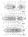
- FIGS. 1 to 4 The installation shown in FIGS. 1 to 4 comprises a manual projector 1 of coating product intended to be used by an operator inside a cabin.
- This projector is supplied with coating material, air and cleaning product through a flexible conduit 2 connected on a set 3 intended to be installed at a level of partition 4 of the coating booth.
- the assembly 3 comprises a base plate 5 pierced with thirty orifices 6 arranged in rows and columns whereas spacers 7 juxtaposed define between them reception and immobilization zones of the downstream ends 10 8 pipes each connected to a source of coating product.
- the spacers 7 are held in position some compared to others by a tightening band 9.
- the number of spacers 7 and the number of orifices of the plate 5 is adapted according to the number of coating products to be used in the installation.
- the downstream end 10 of a pipe 8 is received in a sleeve 11 provided with a valve 12 resiliently loaded by a spring 13 towards a seat 14.
- Two O-rings 15 are disposed downstream of the valve 12.
- the sleeve 11 constitutes an end plug of the pipe 8, this plug being open by displacement of the valve 12 against an elastic force E 1 exerted by the spring 13 and by the pressure of the product inside the pipe 8.
- the waterproof nature of the device formed of the elements 11 at 15 allows to set up the different ends 10 different pipes 8 between two spacers 7, without risk leak.
- the different ends 10 of the pipes 8 between spacers 7 and the band 9 is used to hold the pipes 8 and the spacers 7 in position.
- Each orifice 6 of the plate 5 is equipped with a valve 16 provided with a fixed central element 17 and an annular valve 18 adapted to bear against the element 17 forming a seat, under the effect of a elastic force E 2 exerted by a spring 19.
- the body 20 of the valve 16, which is connected to the element 17 by lugs 21, is extended by a tubular portion 22 intended to be engaged in an outlet bore 23 of the sleeve 11.
- each body 20 of valve 16 thus constitutes the downstream end of a line feed tube formed of a pipe 8 of a sleeve 11 and a valve 16.
- a selection member 30 is formed by a connection that can be selectively mounted on one of the orifices 6, with the exception of two particular orifices 6A and 6B which are respectively connected to a source of air under pressure and to a projector cleaning product source 1.
- the selection member 30 is connected to the orifices 6A and 6B by two flexible tubes 31A and 31B the tubes 31A and 31B being connected to the conduit 2 inside the member 30.
- L member 30 includes a valve 32 comprising a generally cylindrical body 33 and a valve 36 loaded by a spring 35 generating elastic force E 3 in the direction of an internal frustoconical portion of the body 34, the valve itself being frustoconical.
- the member 30 can be moved parallel to the planar end face 5a of the plate 5 so as to selectively move the valve 32 facing one of the valves 16.
- the corresponding orifice 6 which can be identified by a label not shown, and to arrange the member 30 opposite this orifice by a movement in a vertical direction Z-Z ', in the direction of the arrow F 2 or the arrow F 4 , or in a horizontal direction X-X', in the direction of one of the arrows F 1 and F 3 .
- Directions XX 'and ZZ' are parallel to the front face 5a of the plate 5.
- Part 34 thus makes it possible both to immobilize the organ With respect to the plate 5 by cooperation of shapes and Maneuvering the valve 18 of the end valve 16 of the line supply to which the pipe belongs 8.
- a 101 projector is mounted to inside a projection assembly 141 arranged to the end of the arm 142 of a multi-axis robot and including a tank 143 temporary storage of coating product.
- the set 141 is approached to a connector assembly 103 comprising an interface plate 105 which the substantially planar front surface 105 a is provided different orifices 106 connected to pipes 108 for supplying coating material.
- a unit 150 is connected to a source of pressurized air and a source of cleaning product by two flexible conduits 151A and 151B.
- the unit 150 is movable in translation, parallel to the front face 105 a and in two directions XX 'and ZZ', as shown by the arrows F 1 to F 4.
- a control unit of the installation determines which of the orifices 106 must be connected to this tank. Following this determination, unit 150 is moved by any appropriate means, for example by a trolley commanded by jacks, to be arranged immediately below the selected orifice 106.
- the assembly 141 can be brought into the same position for each cleaning-filling operation.
- the unit 150 is then movable substantially in a direction perpendicular to the surface 141 b between two positions, respectively bearing against this surface and at a distance from the set 141.
- the assembly 103 is then mounted on a carriage movable along three orthogonal axes , so that it can bring, as needed, one of the orifices 106 facing the actuator 132.
- the relative position of the actuator and the orifices is adjusted by displacement of the assembly 103 while the assembly 141 keeps the same position for each cleaning-filling operation.
- the assembly 141 is moved by the arm 142, also according to the arrows F 1 to F 4 , to arrive at the position of FIG. 6, where a port 130 for the entry of the coating product into the assembly 141 is arranged. opposite the orifice 106 in question, while a second port 131, provided on a face 141 b of the assembly 141 generally perpendicular to the face 141a in which is provided the orifice 130 is disposed opposite of an outlet port 152 of the unit 150.
- Each orifice 106 is equipped with a valve 112 undergoing an elastic force E 2 generated by a spring 113 in the direction of a seat 114 formed by a frustoconical portion integral with the plate 105.
- An O-ring 115 is disposed around each port 106 and is intended to seal the contact between the surfaces 105a and 141 a around the orifices 106 and 130.
- the valve 112 is displaceably guided in an internal conduit 111 of the plate 105 emerging at the orifice 106 through a washer 112 is itself immobilized with respect to the conduit 111 by a circlip 112 b and against which takes
- the elements 111 to 114 thus constitute an end valve 116 of a coating product supply line, comprising a pipe 108 and which is closed by default under the effect of the force E 2 .
- a chamber 133 Downstream of the orifice 130, a chamber 133 is formed inside which is movable a pusher 134 forming an end of an actuator 132 whose other end comprises a piston 136 undergoing an elastic force E 3 generated by a spring 135 and directed so that it tends to move the pusher 134 away from the orifice 130.
- a duct 137 connects the orifice 131 and the chamber 133, such that air and / or a cleaning product from unit 150 can be directed to the chamber 133.
- the housing 133 is connected to a conduit 102 for supplying the reservoir 143 and, through him, the projector 101.
- XX ' is the axis of symmetry of the orifice 106 and elements 111 and 115. This axis XX' is also that of the orifice 130 and elements 132 to 136 in the positions of Figures 6 to 8. As it more particularly in Figure 7, the duct 137 and the duct 102 are eccentric with respect to the axis XX 'so that a flow of pressurized air and / or trains of air and cleaning product flows in vortices around the actuator 132 in the chamber 133, as represented by the arrow F 6 in Figure 7. This ensures effective cleaning of the actuator 132, especially in case of change of coating product.
- An O-ring 153 is disposed around the orifice 152 and seals between the unit 150 and the face 141 b of the assembly 141. Centering pins of 161, 162 and 163 permit an adequate relative positioning of the elements 105 , 141 and 150.
- This embodiment has the particular advantage that the valve 112 of each of the valves 116 formed in the conduits 111 by the elements 112 to 114 can not be operated by the actuator 132 that if the orifices 130 and 106 are correctly aligned, which avoids any risk of leakage level of these orifices.
- the plates 5 and 105 may be disposed in horizontal planes, their respective front faces 5 a and 105 a being oriented downwards so that an optical detector is disposed under the assembly 3 or 103. Thus, any leakage of product at a port 6 or 106 is detected immediately, the neighboring orifices is not soiled by the product flow along the surface 5 a or 105 a.
- purge valves excess coating material may be provided.
- the coating product flowing in the pipes 8 or 108 is advantageously filtered to reduce the risk of leakage at the seating surfaces of the flaps on the seats correspondents.
Landscapes
- Spray Control Apparatus (AREA)
- Nozzles (AREA)
Claims (10)
- Anlage zum Spritzen von Beschichtunasprodukt mit mindestens einem Projektor (1; 101) und mehreren Versorgungsleitungen (8; 108) des Projektors mit Beschichtungsprodukt, die mit einer Anschlussanordnung (3; 103) verbunden sind, wobei in der Anlage jedes stromabwärtige Ende (6; 106) einer Leitung mit einem Verschlussventil (16; 116) ausgerüstet ist, das von einem gesteuerten Betätigungselement (32; 132) gesteuert werden kann, das am Eingang einer Leitung (2; 102) zur Versorgung des Projektors mit Produkt angeordnet ist, wobei das Betätigungselement und die Anordnung zur Verschiebung zueinander (F1-F4) geeignet sind, derart, dass das Betätigungselement selektiv in Gegenüberstellung eines stromabwärts gelegenen Endes einer der Versorgungsleitungen (8; 108) angeordnet werden kann und das Ventil der Leitung betätigen kann,
dadurch gekennzeichnet, dass die Leitungsenden (6; 106) in Reihen und Spalten angeordnet sind, wobei eine Anordnung (30; 141), die das Betätigungselement (32; 132) umfasst und mit der Versorgungsleitung (2; 102) verbunden ist, parallel zu einer ebenen Fläche (5a; 105a) einer Platte (5; 105) beweglich ist, an der die Leitungsenden münden. - Anordnung nach Anspruch 1, dadurch gekennzeichnet, dass die bewegliche Anordnung (30; 141) entsprechend zwei zu der ebenen Fläche (5a; 105a) parallelen und senkrecht zueinander stehenden Richtungen (X-X'; Z-Z') frei verschoben werden kann, um in Gegenüberstellung zu einem der Leitungsenden (6; 106) zu kommen.
- Anordnung nach einem der vorhergehenden Ansprüche, dadurch gekennzeichnet, dass das Ventil (16; 116) elastische (E2) Rückstellmittel (13; 113) in die geschlossene Stellung umfasst, wobei das Betätigungselement (32,132) geeignet ist, das Ventil gegen die Rückstellmittel zu öffnen.
- Anordnung nach einem der vorhergehenden Ansprüche, dadurch gekennzeichnet, dass das Betätigungselement (32; 132) geeignet ist, teilweise in jedes Ende (6; 106) der Versorgungsleitung (8; 108) in Eingriff gebracht zu werden und ein einen Drücker (34; 134) bildendes Teil umfasst, das einen Ventilkörper (12; 112) des Ventils (16; 116) in eine Öffnungsposition des Ventils verschieben kann.
- Anordnung nach einem der vorhergehenden Ansprüche, dadurch gekennzeichnet, dass die Anschlussanordnung (3) Mittel (6A; 6B) zur Versorgung der Leitung (2) und/oder des Betätigungselementes (32) mit Luft und/oder Reinigungsprodukt einschließt, wobei die Versorgungsmittel für Luft und/oder Reinigungsprcdukt mittels biegsamer Rohrleitungen (31A, 31B) mit der beweglichen Anordnung (30) im Durchlauf verbunden sind.
- Anordnung nach einem der vorhergehenden Ansprüche, dadurch gekennzeichnet, dass das Betätigungselement (32) einen rohrförmigen Stutzen (34) umfasst, der geeignet ist, in das Verschlussventil (16) einzudringen, und in dessen Inneren ein Ventilkörper (36) zum Verschließen der Leitung angeordnet ist, wobei der Stutzen die bewegliche Anordnung (30) in Bezug auf die Platte (5) durch Formschluss festlegen kann.
- Anordnung nach einem der vorhergehenden Ansprüche, dadurch gekennzeichnet, dass das stromabwärts gelegene Ende (10) einer Versorgungsleitung (8) in einer Hülse (11) aufgenommen ist, die einen Stopfen des Endes einer Leitung bildet, der von einem Teil (22) eines Körpers (20) eines Ventils (16) betätigbar ist, der in einer Öffnung (6) einer die ebene Fläche (5a) bildenden Platte (5) vorgesehen ist.
- Anordnung nach einem der vorhergehenden Ansprüche, dadurch gekennzeichnet, dass das Betätigungselement (132) einen Drücker (134) umfasst, der pneumatisch (136) gesteuert wird und translatorisch in einer Kammer (133) beweglich ist, die in einem fest mit dem Projektor (101) verbundenen und einen Behälter (143) zum Speichern von Beschichtungsprodukt umfassenden Körper (141) ausgebildet ist.
- Anordnung nach Anspruch 8, dadurch gekennzeichnet, dass der Körper (141) Mittel (137) zum Anschluss der Kammer (133) an eine Quelle (150) für Luft und/oder Reinigungsprodukt umfasst.
- Anordnung nach Anspruch 9, dadurch gekennzeichnet, dass die Anschlussmittel eine Leitung (137) zur Zirkulation von Luft und/oder Reinigungsprodukt umfasst, wobei die Leitung in Bezug auf eine Symmetrieachse (X-X') des Betätigungselementes (132) exzentrisch ist.
Applications Claiming Priority (3)
| Application Number | Priority Date | Filing Date | Title |
|---|---|---|---|
| FR0000489 | 2000-01-14 | ||
| FR0000489A FR2803776B1 (fr) | 2000-01-14 | 2000-01-14 | Installation de projection de produit de revetement |
| PCT/FR2001/000072 WO2001051216A2 (fr) | 2000-01-14 | 2001-01-10 | Installation de projection de produit de revetement |
Publications (2)
| Publication Number | Publication Date |
|---|---|
| EP1246703A2 EP1246703A2 (de) | 2002-10-09 |
| EP1246703B1 true EP1246703B1 (de) | 2005-06-22 |
Family
ID=8845943
Family Applications (1)
| Application Number | Title | Priority Date | Filing Date |
|---|---|---|---|
| EP01903910A Expired - Lifetime EP1246703B1 (de) | 2000-01-14 | 2001-01-10 | Anlage zum spritzen von beschichtungsmaterial |
Country Status (6)
| Country | Link |
|---|---|
| US (1) | US6651902B2 (de) |
| EP (1) | EP1246703B1 (de) |
| AU (1) | AU3187101A (de) |
| DE (1) | DE60111607T2 (de) |
| FR (1) | FR2803776B1 (de) |
| WO (1) | WO2001051216A2 (de) |
Families Citing this family (25)
| Publication number | Priority date | Publication date | Assignee | Title |
|---|---|---|---|---|
| DE10115471B4 (de) * | 2001-03-29 | 2010-05-27 | Dürr Systems GmbH | Farbwechselsystem für eine Beschichtungsanlage |
| US7506127B2 (en) * | 2001-12-21 | 2009-03-17 | Network Appliance, Inc. | Reconfiguration of storage system including multiple mass storage devices |
| US7127798B1 (en) | 2003-04-04 | 2006-10-31 | Network Appliance Inc. | Method for converting disk drive storage enclosure into a standalone network storage system |
| EP1502659B1 (de) | 2003-07-28 | 2006-02-22 | Dürr Systems GmbH | Farbwechselventilanordnung einer Beschichtungsanlage |
| DE202005022026U1 (de) | 2004-06-03 | 2012-06-21 | Nordson Corp. | Farbwechsel für ein System zum Auftragen von Pulverbeschichtungsmaterial |
| US20060219807A1 (en) * | 2004-06-03 | 2006-10-05 | Fulkerson Terrence M | Color changer for powder coating system with remote activation |
| US8073899B2 (en) * | 2005-04-29 | 2011-12-06 | Netapp, Inc. | System and method for proxying data access commands in a storage system cluster |
| US20080011333A1 (en) * | 2006-07-13 | 2008-01-17 | Rodgers Michael C | Cleaning coating dispensers |
| DE102007029195A1 (de) | 2007-06-25 | 2009-02-19 | Dürr Systems GmbH | Beschichtungseinrichtung mit einer Dosiervorrichtung |
| DE102006058562A1 (de) | 2006-12-12 | 2008-08-14 | Dürr Systems GmbH | Beschichtungseinrichtung mit einer Dosiervorrichtung |
| EP2853312B1 (de) | 2006-12-12 | 2020-01-01 | Dürr Systems AG | ICC-Dosierung |
| DE102008037035B4 (de) * | 2008-08-08 | 2023-05-25 | Dürr Systems Ag | Ventilanordnung eines Lackierroboters |
| EP2268415B1 (de) * | 2008-03-20 | 2015-05-06 | Dürr Systems GmbH | Lackierroboter und zugehöriges betriebsverfahren |
| DE102008015258B4 (de) * | 2008-03-20 | 2023-05-25 | Dürr Systems Ag | Farbwechsler für einen Lackierroboter |
| EP2361691A1 (de) | 2010-02-19 | 2011-08-31 | Ramseier Koatings Technologies AG | Fluidweiche |
| EP2596921A1 (de) * | 2011-11-25 | 2013-05-29 | Staeubli Tec-Systems GmbH | Multikupplungssystem zum Verbinden von mehreren Werkzeugen mit mindestens einer Versorgungseinheit |
| EP2606981B1 (de) * | 2011-12-20 | 2014-04-30 | ABB Technology AG | Farbwechslermodul und Farbwechsler |
| EP2644281B1 (de) * | 2012-03-29 | 2019-05-08 | ABB Schweiz AG | Farbwechsler |
| DE102013007694A1 (de) * | 2013-05-03 | 2014-11-06 | Eisenmann Ag | Wechseleinrichtung für Beschichtungsmedien und Beschichtungssystem zum Beschichten von Gegenständen |
| DE102014011415A1 (de) * | 2014-07-31 | 2016-02-04 | Eisenmann Ag | Wechselvorrichtung für Beschichtungsmedien und Beschichtungssystem zum Beschichten von Gegenständen |
| DE112016001728A5 (de) * | 2015-04-15 | 2018-01-04 | Apson Lackiertechnik Gmbh | Farbwechselsystem |
| DE102015110312B4 (de) | 2015-06-26 | 2019-08-01 | Gema Switzerland Gmbh | Pulverweiche und Pulverabgabesystem mit Pulverweiche |
| DE102015008845A1 (de) * | 2015-07-13 | 2017-01-19 | Eisenmann Se | Wechseleinrichtung und Beschichtungssystem zum Beschichten von Gegenständen |
| DE102016113505A1 (de) * | 2016-07-21 | 2018-01-25 | Apson Lackiertechnik Gmbh | Farbwechselsystem |
| CN108970842B (zh) * | 2018-07-06 | 2023-08-29 | 上海千歌环保科技有限公司 | 一种新型平面换色阀 |
Family Cites Families (15)
| Publication number | Priority date | Publication date | Assignee | Title |
|---|---|---|---|---|
| US2257004A (en) * | 1938-10-07 | 1941-09-23 | Chrysler Corp | Coating material spraying apparatus |
| US3135467A (en) * | 1962-12-03 | 1964-06-02 | Greenman Leo | Automatic all color producing paint spray unit |
| US3240225A (en) * | 1963-01-17 | 1966-03-15 | Benjamin G Barrows | Selecting and purging apparatus |
| US3443578A (en) * | 1966-10-12 | 1969-05-13 | Programmed & Remote Syst Corp | Color select valve for spray guns |
| US3674207A (en) * | 1970-11-06 | 1972-07-04 | Emidio J Carbonetti Jr | Automated paint spray system |
| CH539461A (de) * | 1971-08-02 | 1973-07-31 | Gema Ag App Bau | Pulverspritzpistole zum Verspritzen von verschiedenfarbigen Pulvern aus einem Pistolen-Pulverkanal |
| US3924810A (en) * | 1974-11-04 | 1975-12-09 | Ford Motor Co | Sprayable material changer apparatus |
| US4163523A (en) * | 1976-12-15 | 1979-08-07 | Vincent Raymond A | Multicolor paint dispensing system having a pressure responsive color change valve |
| FR2609252B1 (fr) | 1987-01-02 | 1989-04-21 | Sames Sa | Installation de projection de produit de revetement tel que par exemple une peinture et notamment installation de projection electrostatique de peinture a base d'eau |
| US5221047A (en) * | 1991-08-13 | 1993-06-22 | Gmfanuc Robotics Corporation | Method and system for cleaning a paint supply line and changing paint colors in production paint operations |
| US5215122A (en) * | 1991-12-09 | 1993-06-01 | Aeroquip Corporation | Quick disconnect fluid coupling with integral pressure relief feature |
| US5211197A (en) * | 1992-01-03 | 1993-05-18 | Aeroquip Corporation | Quick disconnect liquid line coupling with volumertric expansion couping element |
| DE4214779C2 (de) | 1992-05-04 | 1995-07-27 | Flaekt Ransburg Bmbh | Handfarbwechsler |
| US5406980A (en) * | 1994-03-28 | 1995-04-18 | Aeroquip Corporation | Deep drawn quick connect coupling |
| FR2777482B1 (fr) | 1998-04-15 | 2000-12-29 | Sames Sa | Procede et installation de projection de produit de revetement au moyen d'un automate equipe d'un reservoir |
-
2000
- 2000-01-14 FR FR0000489A patent/FR2803776B1/fr not_active Expired - Fee Related
-
2001
- 2001-01-10 EP EP01903910A patent/EP1246703B1/de not_active Expired - Lifetime
- 2001-01-10 US US10/169,933 patent/US6651902B2/en not_active Expired - Lifetime
- 2001-01-10 DE DE60111607T patent/DE60111607T2/de not_active Expired - Lifetime
- 2001-01-10 AU AU31871/01A patent/AU3187101A/en not_active Abandoned
- 2001-01-10 WO PCT/FR2001/000072 patent/WO2001051216A2/fr active IP Right Grant
Also Published As
| Publication number | Publication date |
|---|---|
| DE60111607D1 (de) | 2005-07-28 |
| WO2001051216A2 (fr) | 2001-07-19 |
| US6651902B2 (en) | 2003-11-25 |
| FR2803776B1 (fr) | 2002-06-07 |
| FR2803776A1 (fr) | 2001-07-20 |
| WO2001051216A3 (fr) | 2002-02-07 |
| US20030015607A1 (en) | 2003-01-23 |
| EP1246703A2 (de) | 2002-10-09 |
| AU3187101A (en) | 2001-07-24 |
| DE60111607T2 (de) | 2006-04-20 |
Similar Documents
| Publication | Publication Date | Title |
|---|---|---|
| EP1246703B1 (de) | Anlage zum spritzen von beschichtungsmaterial | |
| EP1303359B1 (de) | Verfahren und station zum wechseln von flüssigkeit für eine spritzanlage | |
| CA1293370C (fr) | Installation de projection de produit de revetement tel que par exempleune peinture et notamment installation de projection electrostatique de peinture a base d'eau | |
| BE859130A (fr) | Pistolet distributeur, en particulier pour mousse en polyrethane | |
| EP3519259B1 (de) | Reinigungsvorrichtung zum versprühen von mindestens einer flüssigkeit auf eine zu reinigende oberfläche eines kraftfahrzeugs | |
| EP3065880B1 (de) | Vorrichtung zur ausstattung einer spritzvorrichtung mit einer beschichtungsflüssigkeit | |
| FR2727878A1 (fr) | Appareil pour delivrer des materiaux de revetement conducteur, a unites de transfert comprenant une navette et un dispositif de pompage combines, et procede correspondant | |
| EP0691892B1 (de) | Farbspritzanlage | |
| EP3725421B1 (de) | Anlage zum auftragen eines beschichtungsmittels und reinigungsverfahren einer solchen anlage | |
| FR2815554A1 (fr) | Dispositif et procede d'alimentation de projecteurs et installation de projection equipee d'un tel dispositif | |
| FR3056521B1 (fr) | Dispositif de nettoyage destine a projeter au moins un fluide vers une surface a nettoyer d'un vehicule automobile | |
| WO2002009886A1 (fr) | Dispositif d'alimentation en produit de revetement pulverulent d'un projecteur et installation de projection comprenant un tel dispositif | |
| WO2015063288A1 (fr) | Dispositif d'alimentation d'un projecteur en produit de revetement liquide et outil de montage/demontage d'un tel dispositif | |
| EP1361442A1 (de) | Vorrichtung und Verfahren zur Ausgabe von flüssigen Produkten | |
| EP3066371B1 (de) | Vorrichtung zur versorgung einer spritzvorrichtung mit einer beschichtungsflüssigkeit | |
| FR2576644A1 (fr) | Seringue doseuse et circuit de dosage equipe d'une telle seringue. notamment pour l'industrie agro-alimentaire | |
| CA2841791C (fr) | Station de nettoyage-remplissage pour moyens de projection de produit de revetement | |
| FR2596295A1 (fr) | Appareil pour le nettoyage et le graissage des cables metalliques | |
| FR2815555A1 (fr) | Dispositif et procede d'alimentation de projecteurs et installation de projection equipee d'un tel dispositif | |
| FR2777482A1 (fr) | Procede et installation de projection de produit de revetement au moyen d'un automate equipe d'un reservoir | |
| EP0637740B1 (de) | Vorrichtung mit Reinigungsmittel zum Füllen von geschlossenen Behältern mit einer Nadel | |
| EP1577019A2 (de) | Vorrichtung zur Rückgewinnung von Beschichtungsmaterial aus einem Abfluss | |
| FR2607030A1 (fr) | Installation de projection electrostatique de peinture a base d'eau | |
| FR2796028A1 (fr) | Mecanisme de direction a cremaillere pour vehicule automobile | |
| FR2493225A1 (fr) | Unite stylographique pour machines stylographiques automatiques ou analogues |
Legal Events
| Date | Code | Title | Description |
|---|---|---|---|
| PUAI | Public reference made under article 153(3) epc to a published international application that has entered the european phase |
Free format text: ORIGINAL CODE: 0009012 |
|
| 17P | Request for examination filed |
Effective date: 20020613 |
|
| AK | Designated contracting states |
Kind code of ref document: A2 Designated state(s): AT BE CH CY DE DK ES FI FR GB GR IE IT LI LU MC NL PT SE TR |
|
| AX | Request for extension of the european patent |
Free format text: AL;LT;LV;MK;RO;SI |
|
| RBV | Designated contracting states (corrected) |
Designated state(s): AT BE CH DE FR GB LI |
|
| GRAP | Despatch of communication of intention to grant a patent |
Free format text: ORIGINAL CODE: EPIDOSNIGR1 |
|
| RBV | Designated contracting states (corrected) |
Designated state(s): DE FR GB |
|
| GRAS | Grant fee paid |
Free format text: ORIGINAL CODE: EPIDOSNIGR3 |
|
| GRAA | (expected) grant |
Free format text: ORIGINAL CODE: 0009210 |
|
| AK | Designated contracting states |
Kind code of ref document: B1 Designated state(s): DE FR GB |
|
| REG | Reference to a national code |
Ref country code: GB Ref legal event code: FG4D Free format text: NOT ENGLISH |
|
| REF | Corresponds to: |
Ref document number: 60111607 Country of ref document: DE Date of ref document: 20050728 Kind code of ref document: P |
|
| GBT | Gb: translation of ep patent filed (gb section 77(6)(a)/1977) |
Effective date: 20050819 |
|
| PLBE | No opposition filed within time limit |
Free format text: ORIGINAL CODE: 0009261 |
|
| STAA | Information on the status of an ep patent application or granted ep patent |
Free format text: STATUS: NO OPPOSITION FILED WITHIN TIME LIMIT |
|
| 26N | No opposition filed |
Effective date: 20060323 |
|
| PGFP | Annual fee paid to national office [announced via postgrant information from national office to epo] |
Ref country code: GB Payment date: 20080118 Year of fee payment: 8 |
|
| GBPC | Gb: european patent ceased through non-payment of renewal fee |
Effective date: 20090110 |
|
| PG25 | Lapsed in a contracting state [announced via postgrant information from national office to epo] |
Ref country code: GB Free format text: LAPSE BECAUSE OF NON-PAYMENT OF DUE FEES Effective date: 20090110 |
|
| REG | Reference to a national code |
Ref country code: FR Ref legal event code: PLFP Year of fee payment: 16 |
|
| REG | Reference to a national code |
Ref country code: FR Ref legal event code: PLFP Year of fee payment: 17 |
|
| REG | Reference to a national code |
Ref country code: DE Ref legal event code: R082 Ref document number: 60111607 Country of ref document: DE Representative=s name: PFENNING, MEINIG & PARTNER MBB PATENTANWAELTE, DE Ref country code: DE Ref legal event code: R081 Ref document number: 60111607 Country of ref document: DE Owner name: SAMES KREMLIN, FR Free format text: FORMER OWNER: SAMES TECHNOLOGIES, MEYLAN, FR |
|
| REG | Reference to a national code |
Ref country code: FR Ref legal event code: TP Owner name: SAMES KREMLIN, FR Effective date: 20171010 |
|
| REG | Reference to a national code |
Ref country code: FR Ref legal event code: PLFP Year of fee payment: 18 |
|
| PGFP | Annual fee paid to national office [announced via postgrant information from national office to epo] |
Ref country code: DE Payment date: 20200113 Year of fee payment: 20 |
|
| PGFP | Annual fee paid to national office [announced via postgrant information from national office to epo] |
Ref country code: FR Payment date: 20200130 Year of fee payment: 20 |
|
| REG | Reference to a national code |
Ref country code: DE Ref legal event code: R071 Ref document number: 60111607 Country of ref document: DE |