EP1577019A2 - Vorrichtung zur Rückgewinnung von Beschichtungsmaterial aus einem Abfluss - Google Patents
Vorrichtung zur Rückgewinnung von Beschichtungsmaterial aus einem Abfluss Download PDFInfo
- Publication number
- EP1577019A2 EP1577019A2 EP05356049A EP05356049A EP1577019A2 EP 1577019 A2 EP1577019 A2 EP 1577019A2 EP 05356049 A EP05356049 A EP 05356049A EP 05356049 A EP05356049 A EP 05356049A EP 1577019 A2 EP1577019 A2 EP 1577019A2
- Authority
- EP
- European Patent Office
- Prior art keywords
- pipe
- scraper
- stop block
- downstream
- housing
- Prior art date
- Legal status (The legal status is an assumption and is not a legal conclusion. Google has not performed a legal analysis and makes no representation as to the accuracy of the status listed.)
- Withdrawn
Links
Images


Classifications
-
- B—PERFORMING OPERATIONS; TRANSPORTING
- B05—SPRAYING OR ATOMISING IN GENERAL; APPLYING FLUENT MATERIALS TO SURFACES, IN GENERAL
- B05B—SPRAYING APPARATUS; ATOMISING APPARATUS; NOZZLES
- B05B12/00—Arrangements for controlling delivery; Arrangements for controlling the spray area
- B05B12/14—Arrangements for controlling delivery; Arrangements for controlling the spray area for supplying a selected one of a plurality of liquids or other fluent materials or several in selected proportions to a spray apparatus, e.g. to a single spray outlet
- B05B12/149—Arrangements for controlling delivery; Arrangements for controlling the spray area for supplying a selected one of a plurality of liquids or other fluent materials or several in selected proportions to a spray apparatus, e.g. to a single spray outlet characterised by colour change manifolds or valves therefor
-
- B—PERFORMING OPERATIONS; TRANSPORTING
- B05—SPRAYING OR ATOMISING IN GENERAL; APPLYING FLUENT MATERIALS TO SURFACES, IN GENERAL
- B05B—SPRAYING APPARATUS; ATOMISING APPARATUS; NOZZLES
- B05B12/00—Arrangements for controlling delivery; Arrangements for controlling the spray area
- B05B12/14—Arrangements for controlling delivery; Arrangements for controlling the spray area for supplying a selected one of a plurality of liquids or other fluent materials or several in selected proportions to a spray apparatus, e.g. to a single spray outlet
- B05B12/1481—Arrangements for controlling delivery; Arrangements for controlling the spray area for supplying a selected one of a plurality of liquids or other fluent materials or several in selected proportions to a spray apparatus, e.g. to a single spray outlet comprising pigs, i.e. movable elements sealingly received in supply pipes, for separating different fluids, e.g. liquid coating materials from solvent or air
-
- B—PERFORMING OPERATIONS; TRANSPORTING
- B05—SPRAYING OR ATOMISING IN GENERAL; APPLYING FLUENT MATERIALS TO SURFACES, IN GENERAL
- B05B—SPRAYING APPARATUS; ATOMISING APPARATUS; NOZZLES
- B05B5/00—Electrostatic spraying apparatus; Spraying apparatus with means for charging the spray electrically; Apparatus for spraying liquids or other fluent materials by other electric means
- B05B5/16—Arrangements for supplying liquids or other fluent material
- B05B5/1608—Arrangements for supplying liquids or other fluent material the liquid or other fluent material being electrically conductive
- B05B5/1616—Arrangements for supplying liquids or other fluent material the liquid or other fluent material being electrically conductive and the arrangement comprising means for insulating a grounded material source from high voltage applied to the material
Definitions
- the present invention relates to the technical field of the projection of a surface coating product in the general sense.
- the present invention relates more specifically to a controlled installation of projection of a coating product such as paint.
- the present invention finds a particularly advantageous application but not limiting for the automotive industry in the context of the coating of automobile bodies.
- a painting projection installation comprises at least one, and in general, a series of circulation circuits of paints of different colors, each consisting of a loop in which circulates a painting.
- Each circuit has a pumping station and a supply line for painting projection means arranged in relation of one, and in general, of several paint booths crossed by the objects to paint.
- Each pumping station has at least one reservoir of storage of a given color paint and a pump that pushes the paint into the pipe supplying application means of a manual or automatic nature commonly referred to as projectors, applicators or guns.
- projectors, applicators or guns are connected to an organ of selection called color changer connected to the different pipes by through connections and pipes, antennas or pipes.
- the object of the invention is to remedy the drawbacks set out above in providing a device for recovering the coating product contained in a pipe which ensures the supply from a main pipe of circulation, from the coating product to projection means.
- Another object of the invention is to save the coating product contained in the pipelines between the main waterways and the projection means avoiding their sedimentation.
- the device comprises means for recovering the cleaning fluid from the housing of the downstream stop block.
- the upstream stop block is equipped downstream of the housing, a shutter controlled for the discharge of the cleaning fluid.
- the supply pipe has at least a part with a flexible character of which at least one end is mounted in a connection head which has the receiving housing of the wiper whose internal diameter is substantially equal to the internal diameter of the pipe feed.
- the connecting head of the supply pipe is mounted using removable assembly means on a stop block.
- this connection head is provided with a series of holes opening radially between the receiving housing of the scraper and the end of the supply line and communicating with an outlet.
- the pipe is equipped with a block called intermediate stop for scraper connected on one side at the upstream stop block by a first supply half-pipe and the other side, at the downstream stop block by a second supply half-pipe, the block stopping device having a housing for receiving a scraper circulating in each supply half-pipe, one of the dwellings comprising a seat of receiving a seal fitted to the scraper and communicating with a bypass with the half-pipe opening upstream in the other housing of receiving the scraper which communicates with means for injecting a fluid of cleaning.
- the device comprises at least one support for receiving the stop block downstream equipping the projection means, such a support being provided with the means injecting a cleaning fluid and possibly recovery means cleaning fluid, these injection and recovery means communicating with receiving housing of the scraper via shutters orders.
- the device comprises for a series of supply duct of different coating products, on the one hand a circuit common for the cleaning fluid opening inside the pipes to from the dwellings of downstream stopping blocks and secondly, a common circuit supplying the coating product to the projection means, this circuit communicating on the one hand by a shutter controlled by means of projection and secondly, to each of the supply lines by a shutter ordered.
- the upstream blocking block comprises stitching means on a main circulation pipe.
- the downstream stop block is mounted on a selection block for coating products.
- the selection block is provided with a series of downstream stop blocks for a scraper each connected by a supply line to an upstream stop block for a pig, mounted on a main pipe.
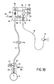
- FIGS. 1A , 1B , 1C are diagrams illustrating in various phases of operation respectively initial, projection and cleaning, a first embodiment of a recovery device adapted for an automatic station with change of colors.
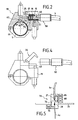
- Figure 2 is a cross-sectional view showing a characteristic detail of the subject of the invention.
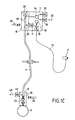
- Figures 2A, 2B, 2C are diagrams illustrating in various phases of operation respectively initial, projection and cleaning, a second embodiment of a recovery device according to the invention adapted for a manual station at one shade.
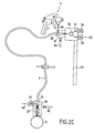
- 3A, 3B and 3C are diagrams illustrating in various phases of operation respectively initial, projection and cleaning, a third embodiment of a recovery device according to the invention for a manual position with change of colors.
- Fig. 4 is a schematic view showing an example of mounting a supply line on a stop block.
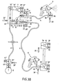
- Fig. 5 is a diagram illustrating a supply pipe made in two parts.
- the object of the invention relates to a device 1 for recovering a coating product forming part of a projection installation 2 of a coating product of which only certain parts necessary for the understanding of the invention have been represented. Indeed, such a projection installation 2 is not described more precisely because it is not part of the object of the invention and its production and operation are well known in the prior art.
- Figs. 1A, 1B, 1C illustrate a first embodiment of a recovery device 1 for a projection installation 2 comprising at least one and in a conventional manner, a series of automatic projection stations 3 with change of the coating product. For the sake of simplification, only an automatic projection station 3 has been shown.
- Each automatic projection station 3 comprises at least one duct 4 ensuring the supply of a coating product of a given color from a main flow line 5, to projection means 6 constituted for example by a gun or an applicator.
- each automatic projection station 3 comprises a color selection block 7 receiving the various supply lines 4 of a coating product of a given shade and each connected to a corresponding main pipe 5 .
- the diagrams show only a pipe 4 and a pipe 5.
- the selection block 7 comprises a common circuit 10 communicating on the one hand with each of the supply lines 4 by a controlled shutter 11 and on the other hand with the projection means 6 by a controlled shutter 12.
- the means projection 6 are connected to the selection block 7 by a flexible antenna 13 generally of short length.
- the device 1 aims to recover the coating product contained in each of the pipes 4 located between a main pipe 5 and the selection block 7.
- the recovery device 1 comprises a wiper 15 disposed within each pipe 4 and provided as illustrated in FIG. 2, means 16 cooperating with the pipe 4 to ensure a seal between the upstream and downstream parts located on either side of the scraper.
- the wiper 15 comprises a rigid body 17 provided with sealing means 16 such as two O-rings in the example illustrated, intended to cooperate with the inner wall of the pipe 4.
- sealing means 16 are adapted to the nature of the pipe which according to an exemplary embodiment has a flexible or flexible character.
- the recovery device 1 comprises for each pipe 4, a block called downstream 18 stop for the scraper, on which is mounted the end of the pipe 4, adjacent injection means 6, and a block said upstream 19 d stop for the scraper 15, on which is mounted the other end of the pipe 4, namely that mounted in relation to the pipe 5.
- the characters upstream and downstream of the stop blocks 18 and 19 are taken into account the meaning normal circulation of the coating product namely from the pipe 5 to the projection means 6.
- at least each stop block 18, 19 is associated with a position sensor 20 to know the position of the wiper in the pipeline, and in particular its end-of-race positions.
- the upstream stop block 19 comprises a housing 21 for receiving the scraper 15 communicating with the pipe 5 via a controlled shutter 23.
- the housing 21 comprises a seat 25 intended to cooperate with at least one seal 26 mounted on the wiper 15 so as to prevent the passage of a fluid from the pipe 4 to the pipe 5.
- the seat 25 has for example a frustoconical section whose small base is directed towards the pipe 5.
- the seat 25 receives the seal 26 carried by a nose 15 1 of the scraper section also frustoconical.
- the scraper 15 thus also assumes a valve function with an opening in the direction 5 - pipe 4 and a closure in the opposite direction namely pipe 4 - pipe 5.
- the downstream stop block 18 also comprises a housing 28 for receiving the wiper 15.
- the downstream stop block 18 is also provided with a path 30 for communication between the pipe 4 and the projection means 6. This communication path 30 opens upstream of the housing 28 and communicates with the projection means 6 via in the illustrated example, the controlled shutter 11, the common circuit 10, the controlled shutter 12 and the antenna 13.
- the recovery device 1 comprises means 32 for injecting a cleaning fluid into the pipe 4 from the housing 28 of the downstream stop block 18 so as to ensure the displacement of the wiper 15 inside the pipe 4, from the downstream stop block 18 to the upstream blocking block 19.
- the injection means 32 inject the cleaning fluid via a controlled shutter 33, in a common circuit 34 for circulating the cleaning fluid communicating with each of the pipes 4 through each of the housings 28.
- a controlled shutter 36 is interposed between each housing 28 and the common circuit 34 for circulating the cleaning fluid. .
- the downstream stop block 18 comprises means 38 for recovering the cleaning fluid introduced beforehand into the pipe 4. These recovery means 38 are connected via a controlled shutter 39 to the common circulation circuit 34. cleaning fluid so as to recover the cleaning fluid from the pipe 4.
- the recovery device 1 comprises recovery means 40 of the cleaning fluid, placed at the upstream block stop 19.
- the stop block 19 thus comprises downstream of the housing 21, an outlet communicating via a controlled shutter 41 to the recovery means 40.
- the recovery device 1 comprises unrepresented control means for controlling the operation of the controlled shutters and the injection means 32 so as to recover the coating product contained in the pipe 4.
- the scraper 15 In the initial position illustrated in FIG. 1A, the scraper 15 is located in the housing 21 of the upstream stop block 19. All shutters controlled are in the closed position.
- the controlled shutters 36 and 39 are placed in the open position before the controlled shutter 23 opens in turn.
- the coating product from the pressurized main line 5 pushes the scraper 15 into line 4 to its other end.
- the controlled shutter 36 is closed and the controlled shutter 11 leaves the passage of the coating product in the common circuit 10.
- the controlled member 12 is opened to allow the coating product to be sent to the projection means 6 (position illustrated in Fig. 1B ).
- the various elements of the recovery device 1 remain in their position during the duration of application of the product or the lifetime of the coating product before its alteration or degradation.
- the controlled shutters 11, 12 are placed in the closed position.
- an operation can be carried out for recovering the coating product contained in the pipe 4.
- a pressurized cleaning fluid 32 is introduced after opening the shutter 33 in the common circuit 34 which after Opening the shutter 36 allows the pressurized fluid to be injected into the pipe 4 via the housing 28.
- the wiper 15 is then pushed towards the upstream stop block 19 by the cleaning product.
- the controlled shutter 23 is open to allow the passage of the coating product of the pipe 4 to the pipe 5.
- the scraper 15 prohibited by its sealing means 16, a mixture between the cleaning fluid and the product coating.
- the scraper 15 closes in the stop position the pipe 4 by its seal 26 forming a valve.
- the controlled shutter 23 is then controlled in closing.
- controlled shutter 41 can be opened in order to purge the pipe 4 and / or to allow the introduction of a cleaning fluid for example. Controlled shutters 41, 36 and 33 are then closed so that the device is returned to its initial state shown in FIG. 1A. It should be noted that the common channel 34, the flexible antenna 13 and the projection means 6 are cleaned in a known manner so that this cleaning operation is not described more precisely.
- FIGS. 1A to 1C illustrate a recovery device 1 according to the invention adapted more particularly for a manual station with a single hue.
- the common elements between the recovery device 1 adapted for a single-shade manual station and the first variant illustrated in FIGS. 1A to 1C will not be described more precisely and carry the same references.
- the downstream stop block 18 is mounted directly on the projection means 6 with a circuit 30 for direct supply of the coating product to the projection means 6.
- This supply circuit 30 opens upstream of the housing 28 which comprises downstream, the controlled shutter 36 which, in the example shown, is a non-return valve.
- the pipe 4 which connects the upstream stop block 19 to the downstream stop block 18 mounted on the projection means 6, has a flexible or flexible character.
- the recovery device 1 comprises a generally fixed support 41 for receiving the downstream stop block 18 so that the receiving housing 28 can communicate with the cleaning fluid injection means 32 and possibly the means recovery 38 of cleaning fluid equipping such a support 41.
- a receiving support 41 is fixedly mounted, for example on a portion of the wall 43 of the paint booth so that the user can place the means of projection 6 on the support 41.
- the downstream stop block 18 is positioned so that the shutter 36 is controlled to be placed in position. opening position allowing during the initial phases and cleaning, the passage of the cleaning fluid.
- the operation of the recovery device 1 is identical to that described in relation to FIGS. 1A to 1C.
- Figs. 3A, 3B and 3C illustrate another alternative embodiment of a recovery device 1 adapted for a manual position with change of colors.
- a manual station with change of colors comprises a color selection block 7 (see description in relation to Figs 1A to 1C ) connected, on the one hand to different pipes 5 by pipes 4 and 4 secondly to projection means 6 using a pipe 4 (see description of Fig. 2A to 2C).
- the device 1 according to the invention aims to recover the coating product contained in two pipes 4, 4 ' located between two projection means 6 and 6' and the shade selection block 7, and in a 4 " connecting the color selection block 7 and the pipe 5.
- the operating principle of the recovery device 1 remains identical to that described above and comprises the three phases illustrated in relation to FIGS. 3A to 3C.
- the cleaning phase of a means of projection 6 requires a period of unavailability during which the user can use another projection means 6.
- the injection means 32 and the shutter 33 associated with said support are controlled to ensure the injection of a cleaning fluid to move the wiper 15 to return the coating product to the shade selection block (FIG. 3C)
- the shutters 23, 11 are closed and the shutter 33 " is open.
- the opening of the controlled shutter 36 " makes it possible to push the scraper 15" into the pipe 4 "in order to recover the coating product in the pipe 5.
- the channel 10 has been cleaned by conventional techniques and a coating product of a different color has reached the shutter 11 ' of the shade selection block 7.
- the shutter 11' is open to allow the wiper 15 ' to be positioned in the housing 28' and the projection of the coating product by the projection means 6 ' (for this, the shutter 39' is of course open.)
- the device 1 aims to recover the coating product circulating in a flexible pipe 4.
- each end of the flexible pipe is mounted in a connection head 50 in which is housed the housing 28, 21 for receiving a scraper 15.
- Each housing is provided with a counter 51 for receiving the end of the pipe 4 so that the internal diameter of the housing is substantially equal to the internal diameter of the pipe 4.
- the connecting head 50 is intended to be mounted in an open well 53 arranged in the upstream blocking block 19. More specifically, the connecting head 50 bears on the bottom of the well 53 which opens by the seat 25 for receiving the nose of the scraper 15 located in the upstream stopping block 19.
- the connecting head 50 is mounted using removable assembly means 54 on the upstream blocking block 19.
- these removable assembly means 54 are constituted by an articulated lever it fits on the connecting head 50 to keep it in position in the mounting well 53, the hinged lever being held by fastening means not shown.
- connection head 50 is provided with a series of holes 60 opening radially between the receiving receptacle 21, 28 of the scraper and the end of the supply pipe 4 to communicate via a controlled shutter with an outlet such that the recovery means 40 or the path 30.
- the upstream stop block 19 as described above is mounted on a pipe 5 by means of stitching means 62 of all types.
- the tapping means 62 allow mounting of the upstream stop block 19 on a new or old pipe 5 .
- the tapping means 62 consist of a hole 63 made in the pipe 5 and in which is engaged a socket 64 carried by the upstream blocking block 19 and provided with a passage 65 for communication with the pipe 4.
- the block stop 19 is fixed on the pipe 5 by means of a jaw 66 hinged to the stop block 19, which after passing around the pipe is fixed to hold the stop block 19 in position .
- each pipe 4 constitutes a unitary element between the stop blocks 18, 19. It should be noted that it can be provided that a pipe 4 has at least two different diameters or two parts. in different materials such as rigid and flexible.
- the supply pipe 4 is equipped with an intermediate stop block 70 for scraper.
- the intermediate stop block 70 which can be fixed for example by passing through a partition 71, is connected on one side to a downstream stop block 19 by a first supply half-pipe 4 1 and the on the other hand, at the upstream stop block 18, by a second half-pipe 4 2 .
- the two half-pipes 4 1 , 4 2 have different diameters but they may have the same diameter.
- the intermediate stop block 70 has on the side of the first half-pipe 4 1 , a housing 21 of the type of an upstream stop block while on the side of the second half-pipe 4 2 , the stop block intermediate has a housing 28 of the type of a downstream block for a scraper.
- the housing 21 thus has a seat 25 for receiving the seal 26 and communicating via a bypass 75 with the half-pipe 4 2 opening outwardly of the housing 28 via a controlled shutter 76.
- Such a diversion 75 allows a part, the routing of the coating product of the pipe 4 1 to the pipe 4 2 (a scraper 15 being placed in the housing 28 of the intermediate stop block whose housing 21 does not contain scraper) and secondly recovering the coating product pushed by the scraper 15 placed in the half-pipe 4 1 , towards the half-pipe 4 2 .
- the housing 28 communicates by a bypass 80 downstream of the housing 21 to allow the passage of the cleaning fluid and consequently the displacement of the wiper 15 in the half-pipe 4 2 .
- this branch 80 is equipped with a controlled shutter 81.
Landscapes
- Details Or Accessories Of Spraying Plant Or Apparatus (AREA)
- Spray Control Apparatus (AREA)
- Coating Apparatus (AREA)
Applications Claiming Priority (2)
| Application Number | Priority Date | Filing Date | Title |
|---|---|---|---|
| FR0402865 | 2004-03-19 | ||
| FR0402865A FR2867702A1 (fr) | 2004-03-19 | 2004-03-19 | Dispositif de recuperation d'un produit de revetement contenu dans une canalisation |
Publications (2)
| Publication Number | Publication Date |
|---|---|
| EP1577019A2 true EP1577019A2 (de) | 2005-09-21 |
| EP1577019A3 EP1577019A3 (de) | 2006-01-11 |
Family
ID=34834202
Family Applications (1)
| Application Number | Title | Priority Date | Filing Date |
|---|---|---|---|
| EP05356049A Withdrawn EP1577019A3 (de) | 2004-03-19 | 2005-03-18 | Vorrichtung zur Rückgewinnung von Beschichtungsmaterial aus einem Abfluss |
Country Status (2)
| Country | Link |
|---|---|
| EP (1) | EP1577019A3 (de) |
| FR (1) | FR2867702A1 (de) |
Cited By (1)
| Publication number | Priority date | Publication date | Assignee | Title |
|---|---|---|---|---|
| WO2014177261A1 (de) * | 2013-05-03 | 2014-11-06 | Eisenmann Ag | Wechseleinrichtung für beschichtungsmedien und beschichtungssystem zum beschichten von gegenstände |
Families Citing this family (1)
| Publication number | Priority date | Publication date | Assignee | Title |
|---|---|---|---|---|
| FR3087361A1 (fr) * | 2018-10-19 | 2020-04-24 | Exel Industries | Procede de projection d'un fluide |
Family Cites Families (4)
| Publication number | Priority date | Publication date | Assignee | Title |
|---|---|---|---|---|
| DE19742588B4 (de) * | 1997-09-26 | 2009-02-19 | Dürr Systems GmbH | Verfahren zum serienweisen Beschichten von Werkstücken |
| DE19805938A1 (de) * | 1998-02-13 | 1999-08-19 | Lactec Gmbh | Verfahren und Vorrichtung zum Beschichten von Teilen |
| WO2003095308A1 (en) * | 2002-05-07 | 2003-11-20 | Behr Systems, Inc. | Method and apparatus for delivering paint to an applicator and flushing same |
| DE10233006B4 (de) * | 2002-07-20 | 2007-07-05 | Eisenmann Lacktechnik Gmbh & Co. Kg | Verfahren zur Versorgung einer Lackapplikationseinrichtung mit Lack |
-
2004
- 2004-03-19 FR FR0402865A patent/FR2867702A1/fr not_active Withdrawn
-
2005
- 2005-03-18 EP EP05356049A patent/EP1577019A3/de not_active Withdrawn
Cited By (4)
| Publication number | Priority date | Publication date | Assignee | Title |
|---|---|---|---|---|
| WO2014177261A1 (de) * | 2013-05-03 | 2014-11-06 | Eisenmann Ag | Wechseleinrichtung für beschichtungsmedien und beschichtungssystem zum beschichten von gegenstände |
| CN105188955A (zh) * | 2013-05-03 | 2015-12-23 | 艾森曼欧洲公司 | 用于涂层介质的更换设备和对物体进行涂装的涂装系统 |
| US9993834B2 (en) | 2013-05-03 | 2018-06-12 | Eisenmann Se | Changeover device for coating media and coating system for coating objects |
| CN105188955B (zh) * | 2013-05-03 | 2018-11-20 | 艾森曼欧洲公司 | 用于涂层介质的更换设备和对物体进行涂装的涂装系统 |
Also Published As
| Publication number | Publication date |
|---|---|
| EP1577019A3 (de) | 2006-01-11 |
| FR2867702A1 (fr) | 2005-09-23 |
Similar Documents
| Publication | Publication Date | Title |
|---|---|---|
| EP0375533B1 (de) | Molchfähige Flüssigkeitsverteilungsleitung mit molchfähigem 3-Wege-Ventil | |
| CH684287A5 (fr) | Coupleur pour assurer le service d'un dispositif de réfrigération, comportant un adaptateur et un orifice de chargement de réfrigérant. | |
| FR2786848A1 (fr) | Coupleur a billes | |
| EP3121070A1 (de) | Reinigungsvorrichtung eines sensors für kraftfahrzeug | |
| FR2646106A1 (fr) | Installation de projection par voie electrostatique d'un produit liquide conducteur et dispositif d'isolation pour un circuit de distribution d'un produit liquide conducteur | |
| EP1246703A2 (de) | Anlage zum spritzen von beschichtungsmaterial | |
| FR2654365A1 (fr) | Installation d'application de produit de revetement conducteur, par voie electrostatique. | |
| BE1009965A3 (fr) | Carottier. | |
| FR2781032A1 (fr) | Dispositif de regulation du debit d'eau avec moyen de decharge de pression | |
| EP0375532B1 (de) | 2-Wege-Ventil zum Stromabwärts-Einbau in einer molchfähigen Flüssigkeitsverteilungsleitung | |
| EP0086130B1 (de) | Selbstdichtende Schnellkupplung versehen mit einer Doppelrückholbewegung mit Verschlussvorrichtung | |
| CH670688A5 (de) | ||
| FR2547639A1 (fr) | Piston de valve d'alimentation d'une capacite puis de decharge brutale de cette capacite et valve de decharge brutale pourvue de ce piston | |
| EP0403345A1 (de) | Verbindungsvorrichtung zwischen zwei Rohrleitungsteilen | |
| WO1989007727A2 (fr) | Raccord-demarreur pour la mise en pression progressive d'installations pneumatiques | |
| EP1577019A2 (de) | Vorrichtung zur Rückgewinnung von Beschichtungsmaterial aus einem Abfluss | |
| FR2890099A1 (fr) | Dispositif de securite pour un puits de petrole et installation de securite associee. | |
| EP1196725A1 (de) | Zuführvorrichtung für eine schneekanone | |
| EP0072746B1 (de) | Handspritzlanze zum Zerstäuben von Pflanzenbehandlungsflüssigkeiten | |
| EP4183944B1 (de) | Vorrichtung zum befüllen eines spülkastens | |
| FR2510228A1 (fr) | Systeme de connexion de raccords automatiques pour tuyaux a des dispositifs de distribution de fluides liquides ou gazeux | |
| EP1737315A2 (de) | Materialausgabevorrichtung mit drehverschluss | |
| BE1009300A3 (fr) | Raccord pour tuyaux destines au passage de fluides sous pression. | |
| FR2552842A1 (fr) | Robinet d'arret a boule avec canal d'ecoulement a profil modifiable | |
| EP1389651A1 (de) | Sprühvorrichtung für pulverförmiges Material wie Mikrokugeln |
Legal Events
| Date | Code | Title | Description |
|---|---|---|---|
| PUAI | Public reference made under article 153(3) epc to a published international application that has entered the european phase |
Free format text: ORIGINAL CODE: 0009012 |
|
| AK | Designated contracting states |
Kind code of ref document: A2 Designated state(s): AT BE BG CH CY CZ DE DK EE ES FI FR GB GR HU IE IS IT LI LT LU MC NL PL PT RO SE SI SK TR |
|
| AX | Request for extension of the european patent |
Extension state: AL BA HR LV MK YU |
|
| PUAL | Search report despatched |
Free format text: ORIGINAL CODE: 0009013 |
|
| AK | Designated contracting states |
Kind code of ref document: A3 Designated state(s): AT BE BG CH CY CZ DE DK EE ES FI FR GB GR HU IE IS IT LI LT LU MC NL PL PT RO SE SI SK TR |
|
| AX | Request for extension of the european patent |
Extension state: AL BA HR LV MK YU |
|
| RIC1 | Information provided on ipc code assigned before grant |
Ipc: B05B 12/14 19800101ALI20051123BHEP Ipc: B05B 15/04 19680901ALI20051123BHEP Ipc: B05B 5/16 19900101AFI20051123BHEP |
|
| AKX | Designation fees paid | ||
| REG | Reference to a national code |
Ref country code: DE Ref legal event code: 8566 |
|
| STAA | Information on the status of an ep patent application or granted ep patent |
Free format text: STATUS: THE APPLICATION IS DEEMED TO BE WITHDRAWN |
|
| 18D | Application deemed to be withdrawn |
Effective date: 20060712 |