EP1245342B1 - mécanisme d'avancement - Google Patents
mécanisme d'avancement Download PDFInfo
- Publication number
- EP1245342B1 EP1245342B1 EP02003088A EP02003088A EP1245342B1 EP 1245342 B1 EP1245342 B1 EP 1245342B1 EP 02003088 A EP02003088 A EP 02003088A EP 02003088 A EP02003088 A EP 02003088A EP 1245342 B1 EP1245342 B1 EP 1245342B1
- Authority
- EP
- European Patent Office
- Prior art keywords
- feed
- gear
- drive
- shaft
- rotary handle
- Prior art date
- Legal status (The legal status is an assumption and is not a legal conclusion. Google has not performed a legal analysis and makes no representation as to the accuracy of the status listed.)
- Expired - Lifetime
Links
- 238000005553 drilling Methods 0.000 claims description 15
- 238000006073 displacement reaction Methods 0.000 claims description 8
- 230000005540 biological transmission Effects 0.000 claims description 4
- 241000425571 Trepanes Species 0.000 abstract 1
- 210000003746 feather Anatomy 0.000 description 3
- 238000013519 translation Methods 0.000 description 3
- 230000014616 translation Effects 0.000 description 3
- 230000001419 dependent effect Effects 0.000 description 1
- 238000011161 development Methods 0.000 description 1
- 230000018109 developmental process Effects 0.000 description 1
- 230000000694 effects Effects 0.000 description 1
Images

Classifications
-
- B—PERFORMING OPERATIONS; TRANSPORTING
- B23—MACHINE TOOLS; METAL-WORKING NOT OTHERWISE PROVIDED FOR
- B23Q—DETAILS, COMPONENTS, OR ACCESSORIES FOR MACHINE TOOLS, e.g. ARRANGEMENTS FOR COPYING OR CONTROLLING; MACHINE TOOLS IN GENERAL CHARACTERISED BY THE CONSTRUCTION OF PARTICULAR DETAILS OR COMPONENTS; COMBINATIONS OR ASSOCIATIONS OF METAL-WORKING MACHINES, NOT DIRECTED TO A PARTICULAR RESULT
- B23Q5/00—Driving or feeding mechanisms; Control arrangements therefor
- B23Q5/22—Feeding members carrying tools or work
- B23Q5/34—Feeding other members supporting tools or work, e.g. saddles, tool-slides, through mechanical transmission
- B23Q5/38—Feeding other members supporting tools or work, e.g. saddles, tool-slides, through mechanical transmission feeding continuously
- B23Q5/385—Feeding other members supporting tools or work, e.g. saddles, tool-slides, through mechanical transmission feeding continuously using a gear and rack mechanism or a friction wheel co-operating with a rail
-
- B—PERFORMING OPERATIONS; TRANSPORTING
- B25—HAND TOOLS; PORTABLE POWER-DRIVEN TOOLS; MANIPULATORS
- B25H—WORKSHOP EQUIPMENT, e.g. FOR MARKING-OUT WORK; STORAGE MEANS FOR WORKSHOPS
- B25H1/00—Work benches; Portable stands or supports for positioning portable tools or work to be operated on thereby
- B25H1/0021—Stands, supports or guiding devices for positioning portable tools or for securing them to the work
- B25H1/0042—Stands
Definitions
- the invention relates to a feed drive with a feed shaft and a mounted on the feed shaft rotary handle for driving the same about an axis of rotation.
- Feed drives find use, for example, on drills, such as core drills.
- the drills are supported on a drilling carriage which is movable along a guide column via a rack or threaded spindle or rope or the like in a feed direction and opposite to this.
- the movement of the drilling carriage along the guide column is effected by means of the usually manually operated feed drive by an associated rotary handle is rotated according to the desired feed about an axis of rotation.
- the object of the invention has been found to propose a feed drive, by means of which two different feeds can be realized in a simple manner and should be mounted in a simple manner.
- the invention further relates to a core drilling device, which is mounted on a drilling carriage on a guide column, wherein the movement of the core drill carrying the drilling carriage is effected by means of a feed drive according to the invention.
- the solution according to the invention provides, instead of a conventional rigidly connected to a feed shaft of the feed drive rotary handle to equip this rotary handle with an additional planetary gear by means of which the rotational movement of the rotary handle is transmitted to the feed shaft of the feed drive.
- Such a ausgestalteter rotary handle can be easily prepared for this purpose devices, z. B. be attached by the output side plugging the planetary gear on the feed shaft.
- the feed drive according to the invention can also be used against existing custom designed rotary handles or automatic feed drives, z. B. core drilling equipment to be replaced.
- the inventively embodied feed drive planetary gear has at least two switching stages, by means of which the feed shaft can be driven via the rotary handle, wherein the drive in each switching stage of the planetary gear with each different gear ratio is effected.
- the planetary gear comprises a housing, an internally toothed ring gear, at least one rotatably mounted on an internally toothed planet carrier and with the ring gear engaged planetary gear and a drive shaft arranged thereon sun gear, and the drive shaft for forming the switching stages axially slidably mounted in the housing, wherein in a first shift stage, the sun gear of the drive shaft with the internal teeth of the planet carrier engages and in a second switching position with the at least one planet gear engages and the housing is secured against rotation about the axis of rotation.
- the planetary gear is spent in its second switching stage, such as by an axial displacement of the rotary handle and concomitant axial displacement of the drive shaft with the sun gear mounted thereon.
- the sun gear no longer engages in the internal toothing of the planet carrier, but meshes with the at least one planetary gear, which in turn runs in the internal toothing of the ring gear.
- the planetary gear set in a conventional manner in function and it is a feed with a reduction, for example in the ratio 1: 4 allows.
- the feed drive can be advantageously equipped with holding means which engage with the housing of the planetary gear when it is placed or plugged onto the feed shaft and secure it against rotation about the axis of rotation.
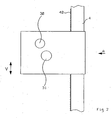
- a feed drive for a core drilling machine (not shown) is shown, which allows a holder of the core drilling machine and the feed thereof.
- the feed drive is supported on a guide column 4 in the manner of a drilling carriage and can be moved in the direction of arrow V, which corresponds to the feed direction, downwards or be moved counter to this direction upwards.
- the guide column 4 has a toothed rack 40 into which engages a drive pinion, not shown, of the feed drive.
- This drive pinion is actuated by means of a feed shaft 31 extending transversely through the feed drive, so that with appropriate rotation of the feed shaft 31 the feed drive with the drilling carriage is moved upwards or downwards in the direction of the arrow V.
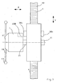
- the rotary handle comprises a hub 17 to which handlebars 18 can be attached with ball heads 19 to effect a rotation by hand about the axis of rotation D.
- handlebars 18 can be attached with ball heads 19 to effect a rotation by hand about the axis of rotation D.
- ball heads 19 to effect a rotation by hand about the axis of rotation D.
- the rotary handle such. B. as a crank or handwheel possible
- a planetary gear is arranged, which is surrounded by a cup-shaped housing 1 and a coming to rest on the hub 17 gear cover 13, which are screwed together by screws 14.
- a drive shaft 9 with sun gear 90 and feather key 12 at least one running between sun gear 90 and internal teeth of the ring gear 8 planetary gear 10 and a likewise having an internal toothing planet carrier 6 arranged in a conventional manner, to form the planetary gear.
- the ring gear 8 is rigidly connected to the housing 1 via the connecting screws 14 between the gear cover 13 and the housing 1.
- the drive shaft 9 is rotatably supported at its end having the feather 12 in a bushing 16 and led out of the gear cover 13 and is on the key 12 positively with the hub 17 into engagement, so that a rotational movement of the hub 17 via the handle bars 18 to the Rotary axis D is transmitted to the drive shaft 9 of the planetary gear.
- the planetary gear is thus the turning handle, consisting of hub 17 and handle bars 18 downstream.
- a socket 5 On the output side of the planetary gear of the at least one planetary gear 10 by means of cylindrical pins 20 supporting planet carrier 6 is connected via a socket 5 with a receiving sleeve 4, in which the feed shaft 31 is positively inserted via an opening 101 in the housing 1.
- a further bushing 3 for the rotatable mounting relative to the housing 1 On the outside of the receiving sleeve 4, a further bushing 3 for the rotatable mounting relative to the housing 1 is provided.
- the receiving sleeve 4 is connected by screws 7 rigidly connected to the planet carrier 6, so that a drive of the inserted into the receiving sleeve 4 feed shaft 31 can be done on the output side via the planetary gear.
- the feed drive has a parallel to the feed shaft 31 extending projecting retaining bolt 30a, which corresponds to a corresponding frontally formed in the housing 1 of the planetary gear receiving bore 100 and engages in this, so that the housing 1 of the planetary gear is secured against rotation about the axis of rotation D, if it is placed according to arrow P on the feed shaft 31 of the feed drive.
- the housing 1 is further releasably secured in this position on the feed shaft 31, so that the rotary handle during operation can not fall off the feed shaft 31.
- the planetary gear is operable for this purpose in two different switching stages in which different ratios between the hub 17 and the feed shaft 31 can be realized. These switch positions are visited by a manually brought about axial displacement of the hub 17 with the handles 18 attached thereto in the direction of arrow P.
- the drive shaft 9 which also carries the fixedly connected to this sun gear, connected via a feather key 12 with the hub 17 and beyond rotatable about the Rotary axis D and arranged displaceably in the axial direction in the sockets 16 and 5 within the housing 1 of the planetary gear.
- the hub 17 is located directly on the housing 1 of the planetary gear.
- the corresponding held on the hub 17 drive shaft is arranged so that the sun gear 90 is in engagement with the internal toothing of the planet carrier 6, but not with the planetary gears 10 and the internal toothing of the ring gear. 8
- the planetary gear is in this way in the in the FIG. 3 shown switching position disabled and there is a rigid drive through the planetary gear ratio in the ratio 1: 1 between the hub 17 of the rotary handle and the feed shaft 31 of the feed drive
- the Hub 17 remains stationary.
- the housing 1 is used in this case as a switching unit between the first and second switching position for the different generated with the rotary handle translations and feeds.
- the handwheel with integrated switchable planetary gear can be easily replaced by a simple handwheel without planetary gear or even against an automated electric drive. This makes it possible to retrofit the inventively designed rotary handle with planetary gear on existing feed drives or use alternately.
- the hub 17 can only with a rotary lever, several handlebars to form a turnstile or with a handwheel or a Crank for generating the rotational movement about the rotation axis D to be equipped.
- the inventively designed rotary handle can be applied in a simple manner on both sides of the feed drive captive.
- the feed drive is formed on both sides with extended ends of the feed shaft 31 and correspondingly corresponding retaining bolts 30a and 30b for engagement in the receiving bores 100 of the housing 1.
- the feed drive is in addition to core drilling machines suitable for use on a variety of machines with manual feed.
Landscapes
- Engineering & Computer Science (AREA)
- Mechanical Engineering (AREA)
- Retarders (AREA)
- Valve-Gear Or Valve Arrangements (AREA)
- Valve Device For Special Equipments (AREA)
- Mechanically-Actuated Valves (AREA)
- Transmission Devices (AREA)
Claims (6)
- Commande d'avancement équipée d'un arbre d'avancement (31) et d'une poignée tournante (17, 18, 19) appliquée sur l'arbre d'avancement pour entraîner ce dernier autour d'un axe de rotation (D), caractérisée par un engrenage planétaire (6, 8, 9, 10) disposé après la poignée tournante, côté sortie sur l'arbre d'avancement, avec au moins deux stades d'enclenchement, au moyen duquel l'arbre d'avancement peut être commandé par la poignée tournante, la commande pouvant être produite, à chaque stade d'enclenchement de l'engrenage planétaire, avec un rapport de transmission respectivement différent.
- Commande d'avancement selon la revendication 1, caractérisée en ce que l'engrenage planétaire comprend un boîtier (1), une roue à denture intérieure (8), au moins un pignon satellite (10) monté à rotation sur un porte-satellite à denture intérieure (6) et se trouvant en prise avec la roue (8), et un arbre de commande (9) sur lequel est aménagée une roue solaire (90), et en ce que l'arbre de commande (9) est monté à coulissement axial dans le boîtier (1) pour former les stades d'enclenchement, la roue solaire (90) de l'arbre de commande (9) venant en prise, dans un premier stade d'enclenchement, avec la denture intérieure du porte-satellite (6) et venant en prise, dans une seconde position d'enclenchement, avec le au moins un pignon satellite (10) et le boîtier (1) étant protégé contre une torsion autour de l'axe de rotation (D).
- Commande d'avancement selon la revendication 2, caractérisée en ce que le coulissement axial de l'arbre de commande (9) peut être produit par la poignée tournante.
- Commande d'avancement selon l'une quelconque des revendications 1 à 3, caractérisée en ce que le dispositif de commande d'avancement présente des moyens de maintien, qui viennent en prise avec le boîtier (1) de l'engrenage planétaire et protègent contre une torsion autour de l'axe de rotation (D).
- Commande d'avancement selon l'une quelconque des revendications 1 à 4, caractérisée en ce qu'un rapport de multiplication de 1:1 entre la poignée tournante et l'arbre d'avancement peut être généré au premier stade d'enclenchement de l'engrenage planétaire et en ce qu'un rapport de démultiplication, par exemple, d'environ 1:4, entre la poignée tournante et l'arbre d'avancement de la commande d'avancement peut être généré au second stade d'enclenchement.
- Appareil de carottage muni d'un chariot de forage déplaçable le long d'une colonne de guidage dans le sens d'avancement et portant l'appareil de carottage, avec une commande d'avancement selon l'une quelconque des revendications précédentes.
Applications Claiming Priority (4)
| Application Number | Priority Date | Filing Date | Title |
|---|---|---|---|
| DE10116111 | 2001-03-30 | ||
| DE10116111 | 2001-03-30 | ||
| DE10134928A DE10134928B4 (de) | 2001-03-30 | 2001-07-18 | Verwendung eines Vorschubantriebes |
| DE10134928 | 2001-07-18 |
Publications (3)
| Publication Number | Publication Date |
|---|---|
| EP1245342A2 EP1245342A2 (fr) | 2002-10-02 |
| EP1245342A3 EP1245342A3 (fr) | 2004-11-10 |
| EP1245342B1 true EP1245342B1 (fr) | 2008-06-04 |
Family
ID=26008970
Family Applications (1)
| Application Number | Title | Priority Date | Filing Date |
|---|---|---|---|
| EP02003088A Expired - Lifetime EP1245342B1 (fr) | 2001-03-30 | 2002-02-13 | mécanisme d'avancement |
Country Status (3)
| Country | Link |
|---|---|
| EP (1) | EP1245342B1 (fr) |
| AT (1) | ATE397516T1 (fr) |
| DE (1) | DE50212341D1 (fr) |
Families Citing this family (3)
| Publication number | Priority date | Publication date | Assignee | Title |
|---|---|---|---|---|
| CN109750977A (zh) * | 2017-11-01 | 2019-05-14 | 陈晓新 | 一种新型钻井增扭矩消颤除振动工具 |
| CN109594910A (zh) * | 2018-12-20 | 2019-04-09 | 刘尚银 | 手摇式卷帘防盗百叶窗及其工作方法 |
| CN114101715B (zh) * | 2021-11-17 | 2024-03-29 | 集创机械制造无锡有限公司 | 一种小型法兰密封面加工设备 |
Family Cites Families (5)
| Publication number | Priority date | Publication date | Assignee | Title |
|---|---|---|---|---|
| BE502813A (fr) * | 1950-04-26 | |||
| US2995960A (en) * | 1960-07-11 | 1961-08-15 | Black & Decker Mfg Co | Two-speed feeding and retracting means for a portable drill stand |
| GB991082A (en) * | 1963-04-18 | 1965-05-05 | Birfield Eng Ltd | Improvements in or relating to feed mechanisms |
| GB1378909A (en) * | 1972-03-18 | 1974-12-27 | Gkn Transmissions Ltd | Epicyclic gear change assemblies |
| JP2904919B2 (ja) * | 1989-04-07 | 1999-06-14 | ツァーンラートファブリーク、フリードリッヒスハーフェン、アクチエンゲゼルシャフト | 切換変速装置付きの駆動装置 |
-
2002
- 2002-02-13 EP EP02003088A patent/EP1245342B1/fr not_active Expired - Lifetime
- 2002-02-13 DE DE50212341T patent/DE50212341D1/de not_active Expired - Lifetime
- 2002-02-13 AT AT02003088T patent/ATE397516T1/de not_active IP Right Cessation
Also Published As
| Publication number | Publication date |
|---|---|
| DE50212341D1 (de) | 2008-07-17 |
| ATE397516T1 (de) | 2008-06-15 |
| EP1245342A3 (fr) | 2004-11-10 |
| EP1245342A2 (fr) | 2002-10-02 |
Similar Documents
| Publication | Publication Date | Title |
|---|---|---|
| DE69400262T2 (de) | Motorgetriebenes Gerät und Mechanismus dafür | |
| DE1957235C3 (de) | Motorisch angetriebene Schlagbohrmaschine | |
| EP2517811B1 (fr) | Dispositif de forage | |
| DE4213291C2 (de) | Getriebeeinrichtung einer handgeführten Bohrhammermaschine | |
| EP1886769B1 (fr) | Machine-outil dotée d'un train épicycloïdal à plusieurs niveaux | |
| EP0373106B1 (fr) | Outil à main avec boîte d'engrenage | |
| DE3904085C2 (fr) | ||
| DE102012213724B4 (de) | Planetengetriebe für eine Handwerkzeugmaschine | |
| DE102019123288A1 (de) | Gangschaltung für einen elektromotorischen Fahrrad-Zusatzantrieb | |
| DE19753304A1 (de) | Vorrichtung zur Arretierung einer Welle | |
| EP1886768B1 (fr) | Machine-outil dotée d'engrenages à plusieurs étapes | |
| DE19528924A1 (de) | Elektrische Schlagbohrmaschine | |
| DE4201849C1 (fr) | ||
| DE102006061600A1 (de) | Elektrohandwerkzeuggerät | |
| DE10134928B4 (de) | Verwendung eines Vorschubantriebes | |
| DE4305967C2 (de) | Schaltvorrichtung zur Spindelarretierung für Elektrowerkzeuge | |
| EP1245342B1 (fr) | mécanisme d'avancement | |
| EP0040261A1 (fr) | Outil électrique avec engrenage à deux pas | |
| DE2940827C2 (fr) | ||
| DE4216808A1 (de) | Bohr- und Meisselgerät | |
| DE102005038681A1 (de) | Schaltanordnung zum Verschieben einer Schaltgabel | |
| EP0272434A2 (fr) | Perceuse osseuse | |
| EP1566238B1 (fr) | Système électrique de mouvement linéaire avec un accouplement direct entre un système vis-écrou et un module moteur | |
| DE3540605A1 (de) | Elektrowerkzeug mit einem zweiganggetriebe | |
| EP1127644B1 (fr) | Outil électrique à main |
Legal Events
| Date | Code | Title | Description |
|---|---|---|---|
| PUAI | Public reference made under article 153(3) epc to a published international application that has entered the european phase |
Free format text: ORIGINAL CODE: 0009012 |
|
| AK | Designated contracting states |
Kind code of ref document: A2 Designated state(s): AT BE CH CY DE DK ES FI FR GB GR IE IT LI LU MC NL PT SE TR |
|
| AX | Request for extension of the european patent |
Free format text: AL;LT;LV;MK;RO;SI |
|
| PUAL | Search report despatched |
Free format text: ORIGINAL CODE: 0009013 |
|
| AK | Designated contracting states |
Kind code of ref document: A3 Designated state(s): AT BE CH CY DE DK ES FI FR GB GR IE IT LI LU MC NL PT SE TR |
|
| AX | Request for extension of the european patent |
Extension state: AL LT LV MK RO SI |
|
| 17P | Request for examination filed |
Effective date: 20050510 |
|
| AKX | Designation fees paid |
Designated state(s): AT BE CH LI |
|
| RBV | Designated contracting states (corrected) |
Designated state(s): AT CH DE LI |
|
| REG | Reference to a national code |
Ref country code: DE Ref legal event code: 8566 |
|
| RBV | Designated contracting states (corrected) |
Designated state(s): AT CH DE LI |
|
| RAP1 | Party data changed (applicant data changed or rights of an application transferred) |
Owner name: GOELZ GMBH |
|
| GRAP | Despatch of communication of intention to grant a patent |
Free format text: ORIGINAL CODE: EPIDOSNIGR1 |
|
| RTI1 | Title (correction) |
Free format text: FEED MECHANISM |
|
| GRAS | Grant fee paid |
Free format text: ORIGINAL CODE: EPIDOSNIGR3 |
|
| GRAA | (expected) grant |
Free format text: ORIGINAL CODE: 0009210 |
|
| AK | Designated contracting states |
Kind code of ref document: B1 Designated state(s): AT CH DE LI |
|
| REG | Reference to a national code |
Ref country code: CH Ref legal event code: EP |
|
| REF | Corresponds to: |
Ref document number: 50212341 Country of ref document: DE Date of ref document: 20080717 Kind code of ref document: P |
|
| PLBE | No opposition filed within time limit |
Free format text: ORIGINAL CODE: 0009261 |
|
| STAA | Information on the status of an ep patent application or granted ep patent |
Free format text: STATUS: NO OPPOSITION FILED WITHIN TIME LIMIT |
|
| 26N | No opposition filed |
Effective date: 20090305 |
|
| PG25 | Lapsed in a contracting state [announced via postgrant information from national office to epo] |
Ref country code: AT Free format text: LAPSE BECAUSE OF NON-PAYMENT OF DUE FEES Effective date: 20090213 |
|
| PGFP | Annual fee paid to national office [announced via postgrant information from national office to epo] |
Ref country code: CH Payment date: 20130227 Year of fee payment: 12 |
|
| REG | Reference to a national code |
Ref country code: CH Ref legal event code: PL |
|
| PG25 | Lapsed in a contracting state [announced via postgrant information from national office to epo] |
Ref country code: CH Free format text: LAPSE BECAUSE OF NON-PAYMENT OF DUE FEES Effective date: 20140228 Ref country code: LI Free format text: LAPSE BECAUSE OF NON-PAYMENT OF DUE FEES Effective date: 20140228 |
|
| PGFP | Annual fee paid to national office [announced via postgrant information from national office to epo] |
Ref country code: DE Payment date: 20200403 Year of fee payment: 19 |
|
| REG | Reference to a national code |
Ref country code: DE Ref legal event code: R119 Ref document number: 50212341 Country of ref document: DE |
|
| PG25 | Lapsed in a contracting state [announced via postgrant information from national office to epo] |
Ref country code: DE Free format text: LAPSE BECAUSE OF NON-PAYMENT OF DUE FEES Effective date: 20210901 |