EP1566238B1 - Système électrique de mouvement linéaire avec un accouplement direct entre un système vis-écrou et un module moteur - Google Patents
Système électrique de mouvement linéaire avec un accouplement direct entre un système vis-écrou et un module moteur Download PDFInfo
- Publication number
- EP1566238B1 EP1566238B1 EP04002750A EP04002750A EP1566238B1 EP 1566238 B1 EP1566238 B1 EP 1566238B1 EP 04002750 A EP04002750 A EP 04002750A EP 04002750 A EP04002750 A EP 04002750A EP 1566238 B1 EP1566238 B1 EP 1566238B1
- Authority
- EP
- European Patent Office
- Prior art keywords
- main housing
- linear drive
- drive according
- gear
- linear
- Prior art date
- Legal status (The legal status is an assumption and is not a legal conclusion. Google has not performed a legal analysis and makes no representation as to the accuracy of the status listed.)
- Expired - Lifetime
Links
- 230000008878 coupling Effects 0.000 title description 16
- 238000010168 coupling process Methods 0.000 title description 16
- 238000005859 coupling reaction Methods 0.000 title description 16
- 230000033001 locomotion Effects 0.000 claims description 18
- 230000000295 complement effect Effects 0.000 claims description 4
- 238000000034 method Methods 0.000 claims description 4
- 230000008569 process Effects 0.000 claims description 3
- 230000005540 biological transmission Effects 0.000 abstract description 17
- 238000010079 rubber tapping Methods 0.000 description 12
- 238000013461 design Methods 0.000 description 5
- 238000006243 chemical reaction Methods 0.000 description 3
- 238000009434 installation Methods 0.000 description 3
- 230000007547 defect Effects 0.000 description 2
- 230000001419 dependent effect Effects 0.000 description 2
- 238000003780 insertion Methods 0.000 description 2
- 230000037431 insertion Effects 0.000 description 2
- 230000013011 mating Effects 0.000 description 2
- 239000011295 pitch Substances 0.000 description 2
- 230000008439 repair process Effects 0.000 description 2
- 238000013519 translation Methods 0.000 description 2
- 238000011144 upstream manufacturing Methods 0.000 description 2
- 230000009286 beneficial effect Effects 0.000 description 1
- 238000001514 detection method Methods 0.000 description 1
- 238000011161 development Methods 0.000 description 1
- 230000018109 developmental process Effects 0.000 description 1
- 238000006073 displacement reaction Methods 0.000 description 1
- 230000001747 exhibiting effect Effects 0.000 description 1
- 230000002093 peripheral effect Effects 0.000 description 1
- 230000009467 reduction Effects 0.000 description 1
- 230000004044 response Effects 0.000 description 1
Images


Classifications
-
- B—PERFORMING OPERATIONS; TRANSPORTING
- B23—MACHINE TOOLS; METAL-WORKING NOT OTHERWISE PROVIDED FOR
- B23Q—DETAILS, COMPONENTS, OR ACCESSORIES FOR MACHINE TOOLS, e.g. ARRANGEMENTS FOR COPYING OR CONTROLLING; MACHINE TOOLS IN GENERAL CHARACTERISED BY THE CONSTRUCTION OF PARTICULAR DETAILS OR COMPONENTS; COMBINATIONS OR ASSOCIATIONS OF METAL-WORKING MACHINES, NOT DIRECTED TO A PARTICULAR RESULT
- B23Q5/00—Driving or feeding mechanisms; Control arrangements therefor
- B23Q5/22—Feeding members carrying tools or work
- B23Q5/34—Feeding other members supporting tools or work, e.g. saddles, tool-slides, through mechanical transmission
- B23Q5/38—Feeding other members supporting tools or work, e.g. saddles, tool-slides, through mechanical transmission feeding continuously
- B23Q5/40—Feeding other members supporting tools or work, e.g. saddles, tool-slides, through mechanical transmission feeding continuously by feed shaft, e.g. lead screw
-
- B—PERFORMING OPERATIONS; TRANSPORTING
- B23—MACHINE TOOLS; METAL-WORKING NOT OTHERWISE PROVIDED FOR
- B23Q—DETAILS, COMPONENTS, OR ACCESSORIES FOR MACHINE TOOLS, e.g. ARRANGEMENTS FOR COPYING OR CONTROLLING; MACHINE TOOLS IN GENERAL CHARACTERISED BY THE CONSTRUCTION OF PARTICULAR DETAILS OR COMPONENTS; COMBINATIONS OR ASSOCIATIONS OF METAL-WORKING MACHINES, NOT DIRECTED TO A PARTICULAR RESULT
- B23Q5/00—Driving or feeding mechanisms; Control arrangements therefor
- B23Q5/22—Feeding members carrying tools or work
- B23Q5/28—Electric drives
Definitions
- the invention relates to an electric linear drive, with a main housing, on which a tapping of a linear movement enabling tap is mounted linearly adjustable, which is drivingly coupled to the output part of a arranged in the main housing spindle drive whose rotatable input part via a coupling with a back to the Main housing arranged electric motor is in drive connection.
- a known from US 5676016 or EP-0726118-A electric linear drive of this type has a main housing in which a spindle drive is housed, which is coupled to a slide-like tapping part. If the spindle-like input part of the spindle drive causes a rotational movement, the output part of the spindle drive executes a linear movement, which can be tapped off at the tapping part.
- the rotational movement of the input part is caused by a arranged at the rear of the main housing electric motor, the output part is rotatably connected via a coupling with the input part of the spindle drive.
- the well-known linear drive can be assembled only meaningful that the electric motor is installed together with the previously attached thereto spindle drive. The same applies to a disassembly in case of repair, because the coupling for removing the axial cohesion ensuring cross pins is not readily accessible.
- the coupling is designed as a pure plug-in coupling and formed directly by a toothed gear, which rotatably connected to the input part of the spindle drive, fixed with respect to the main housing fixed first gear and a gear connected to the output part of the electric motor second gear ,
- the second transmission gear together with the electric motor is part of a motor module, irrespective of the currently occupied between the input part and the output part of the spindle drive relative position, and at the same time making or canceling the gear engagement between the two gear wheels, attachable to the back of the main housing and is removable.
- the electric motor can be installed and deinstalled independently of the spindle drive.
- the coupling designed purely as a plug-in coupling does not require mutual locking of the elements to be coupled to one another, so that the clutch engagement is automatically established or canceled when the electric motor is attached to and removed from the motor module. This is not only beneficial for initial assembly and servicing. Even with a necessary conversion of the linear drive to a different performance or another translation, the problem-free replacement option proves to be advantageous.
- the length required for the coupling measures length can be reduced if necessary by the configuration of the plug-in coupling as a gear transmission, since the meshing gear wheels can be arranged transversely to the longitudinal axis of the linear drive side by side.
- the two gear wheels are expediently designed as spur gears toothed on the outer circumference, which are arranged offset parallel to each other and whose axes of rotation are aligned in the direction of an imaginary mounting axis along which the motor unit is displaced during attachment or removal to or from the main housing.
- the two transmission gears arrive in a particularly simple manner immediately during the piecing and removal process in or out of engagement with each other.
- Particularly useful is an embodiment of the spur gears with a circumferential spur toothing, although in principle a helical design would be possible.
- the motor module can be assembled and disassembled very quickly if necessary, it is expediently locked in the state which is connected to the main housing only by one or more fastening screws. Once the fixing screws have been loosened, the motor module can be easily removed from the main housing.
- the electric motor can be accommodated as a structural unit in a module housing of the motor module. It is used in particular detachable, so that if necessary, an exchange is possible, for example in the event of a defect or for conversion to a different engine performance.
- a plurality of motor modules can alternatively be provided, which differ in the tappable at the second transmission gear speed and which can be optionally installed on a main housing to drive the spindle drive - according to the particular application - different speeds.
- a much simpler solution provides to resort to identical electric motors, however, to provide between the electric motor and the second gear gear for under- or translation serving intermediate gear, which converts the rotational speed of the electric motor in the desired speed of the second gear wheel with a corresponding design.
- the intermediate gear is designed in particular as a planetary gear.
- the main housing, the tapping part and the Spindeltrieb.können be summarized to a work unit, wherein the spindle drive is designed as a module which is releasably fixed in a receptacle of the main housing.
- the spindle drive can thus be installed and uninstalled as a whole, which facilitates repairs and on the other hand allows easy conversion of the linear drive to other thread pitches or other types of spindle drive. In this way, for example, an equipment with either a ball screw or a sliding screw can be made.
- the motor module can be equipped with an encoder that evaluates the rotational movement of the electric motor and thus can be used quasi as a displacement measuring system for detecting the position of the linearly adjustable tapping part.
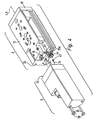
- the electric linear drive designated overall by reference numeral 1, comprises a working unit 2 and a motor module 3 detachably coupled thereto. These two components are arranged successively in the direction of an imaginary mounting axis 4 indicated by dash-dotted lines. The latter simultaneously forms the longitudinal axis of the linear drive. 1
- the working unit 2 contains a designated for better distinction as a main housing 5 elongated housing whose longitudinal axis 6 coincides with the mounting axis 4.
- a main housing 5 elongated housing whose longitudinal axis 6 coincides with the mounting axis 4.
- a main housing 5 elongated housing whose longitudinal axis 6 coincides with the mounting axis 4.
- a tapping part 12 is mounted linearly adjustable so that it can perform relative to the main housing 5 by a double arrow marked, reciprocating linear motion 13. The direction of movement is rectified with the longitudinal axis 6.
- the motor module 3 is attached to the back of the main housing 5 and includes an electric motor 14, which via the Spindle drive 8 is in operative connection with the tapping part 12, so that from the output from the electric motor 14 rotational movement for the output member 12 desired linear motion 13 is derived.
- fastening means 15 of any kind are provided, via which any component can be attached, which is to be adjusted linearly, for example, a part of a machine or a gripper used for handling purposes.
- the tapping part 12 is formed like a slide in the embodiment and slidably mounted along the main housing 5 along with the interposition of suitable linear guide means 16.
- a yoke portion 17 of the Abgriffsteils 12 protrudes in front of the front end face 18 of the main housing 5 in one of the front opening provided there 22 of the receptacle 7 upstream region.
- the spindle drive 8 has two spaced apart front and rear bearing parts 23a, 23b, which are fixed in the interior of the receptacle 7, wherein the front bearing part 23a in the region of the front opening 22 and the rear bearing part 23b in the region of the rear end face 24 of the main housing 5 out opening rear opening 25 of the receptacle 7 is placed. Between the two bearing parts 23a, 23b extending in the manner of a threaded rod-like input part 26 of the spindle drive 8, which is in each case rotatably mounted in the two bearing parts 23a, 23b. By appropriate design of at least one of these two bearings is also ensured that the input part 26 is fixed immovably in the longitudinal direction.
- the motor module 3 is attached with an end-face installation surface 32 to the rear end face 24 of the main housing 5 of the working unit 2.
- the installation surface 32 is located on a for better distinction as a module housing 33 designated housing of the motor module 3, in which the electric motor 14, in particular in the manner of a cartridge, housed.
- the assembly of the motor module 3 on the main housing 5 is carried out by applying in the direction of the mounting axis 4 in the context of an illustrated by an arrow Ansetzschi 34.
- the removal of the motor module 3 from the main body 5 is done by a movement in the opposite direction.
- the attachment of the motor module 3 to the main housing 5 is a plug-in operation.
- complementary first and second plug centering means 35a, 35b engage each other transversely to the mounting axis 4 in a form-fitting manner. In this way, the relative position of the main housing 5 and motor module 3 is defined transversely to the longitudinal axis 6 of the main housing 5.
- the first plug centering means 35a associated with the main housing 5 are preferably formed by a section of the rear bearing part 23b projecting beyond the rear end face 24 of the main housing 5.
- This section has at least partially a substantially cylindrical outer contour, which matingly engages in a complementary recess 36 of the module housing 33 which is open towards the installation surface 32 and which represents the second insertion centering means 35b.
- At least the rear bearing part 23b is screwed into the receptacle 7.
- the peripheral surface of the above the main housing 5 projecting portion of the rear bearing portion 23b at diametrically opposite locations, each with a flat 37 is provided. Even a polygonal contour, for example as a hexagon, would be conceivable.
- the attached to the main housing 5 and in particular infected motor module 3 is axially locked by at least one mounting screw 37 in the scheduled position so that it can not be removed in the direction of the mounting axis 4.
- the fastening screws 37 thus have the purpose of ensuring the axial cohesion of the main housing 5 and engine module 3.
- the fastening screws 37 are released, so that the motor module 3 can be removed.
- the fastening screws 37 can also fulfill an anti-rotation function between the motor module 3 and the drive unit 2.
- each fastening screw 37 passes through the module housing 33, on which it is supported by a head 38, and is detachably screwed into a threaded bore 39 of the main housing 5 open to the rear end face 24.
- a pure plug-in coupling 41 is provided for torque coupling of the input part 26 of the spindle drive 8 with the electric motor 14.
- the elements to be coupled can with a mere mating operation are engaged so that the desired rotational drive is achieved.
- This plug-in procedure is identical to the Ansetzschi 34 of the motor module 3.
- the release of the clutch engagement is done, again independently, when removing the motor module 3 in the direction of the mounting axis. 4
- the plug-in coupling 41 is formed directly by a gear transmission 43. To this end, it contains a rotatably connected to the input part 26 of the spindle drive 8 first transmission gear 44 and a drivingly coupled to the rotatably driven member 46 second transmission gear 45.
- the first transmission gear 44 is arranged coaxially with the input part 26, wherein its axis of rotation 47 is the same as the mounting axis 4 is aligned. The latter also applies to the axis of rotation 48 of the second transmission gear 45.
- the two transmission gears 44, 45 are expediently designed as so-called straight-toothed spur gears, in which the teeth sit on the radially oriented outer circumference. Further, by the axes of rotation 47, 48 are arranged so that they are parallel offset from each other, results in a manufactured clutch engagement a state in which the two gear wheels 44, 45 are arranged in the direction of the mounting axis 4 at the same height side by side.
- the first transmission gear 44 protrudes from the rear over the main housing 5, wherein it is also upstream of the first insertion centering means 35a.
- the second transmission gear 45 is seated in a gear housing 51 forming a section of the module housing 33, wherein the corresponding receiving space of the gear housing 51 is accessible via the recess 36.
- a reverse arrangement is also possible. If the motor module 3 is attached to the main housing 5 while the attachment movement 34 is being executed, the first transmission gearwheel 44 emerges through the recess 36 into the gear housing 51, wherein its toothing is plugged onto the toothing of the second gear wheel 45, so that the two gear teeth 44, 45 mesh according to FIG. 3 at one point of its circumference.
- the motor module 3 can be installed and uninstalled at any such relative position. Thus, for example, it is possible to replace the motor module 3 in the event of a defect without having to remove the working unit 2 from the place of use and while maintaining the instantaneous position of the tapping part 12.
- the output speed of the electric motor can be under-or translate as needed and thereby specify the dependent of the speed of the electric motor 14 speed of the second transmission gear 45.
- the intermediate gear 52 is preferably a planetary gear.
- the second transmission gear 45 is expediently arranged coaxially with the output part 46 of the electric motor 14.
- the two gear wheels 44, 45 are arranged laterally offset from each other, even a relatively large transverse dimensions exhibiting electric motor 14 can still be accommodated in the module housing 33, that there is the possibility by the motor module 3 and the main housing 5 in a common plane to define lying mounting surface 53, via which the linear drive can be fixed to a support structure.
- the entire spindle drive 8 is expediently designed as a uniformly manageable module, which can be used as a structural unit in the receptacle 7 and can also be removed again if necessary.
- the linear drive can be quickly converted if necessary, for example, to a spindle drive 8 with greater or lesser thread pitch.
- the assembly of the entire linear drive proves to be particularly simple due to this modular design.
- the required for the operation of the electric motor 14 electrical energy and actuation signals can be fed via a provided on the module housing 33 electromechanical interface 54. At this interface, moreover, position signals can be tapped, which provides an arranged in the module housing 33, not shown encoder in response to the rotational movement and / or rotational position of the output member 46 of the electric motor 14. In this way, an indirect detection of the position of the embodiment designed as a slide body tapping part 12 is possible.
Claims (16)
- Entraînement linéaire électrique, avec un boîtier principal (5) sur lequel une partie de prise (12) permettant de capter un mouvement linéaire est montée mobile de façon linéaire, qui est couplée en entraînement à la partie de sortie (27) d'une commande à vis (8) placée dans le boîtier principal (5), dont la partie d'entrée rotative (26) est en liaison d'entraînement, par l'intermédiaire d'un accouplement, avec un moteur électrique (14) placé à l'arrière sur le boîtier principal (5), caractérisé en ce que l'accouplement est réalisé en accouplement à enfichage pur (41) et est formé directement par un mécanisme (43) de roues dentée, qui comprend une première roue dentée (44) stationnaire par rapport au boîtier principal (5), reliée de manière solidaire en rotation à la partie d'entrée (26) de la commande à vis (8), et une deuxième roue dentée (45) reliée à la partie de sortie (46) du moteur électrique (14), la deuxième roue dentée (45) faisant partie, avec le moteur électrique (14), d'un module moteur (3) qui peut être monté sur et déposé depuis la face arrière du boîtier principal (5) indépendamment de la position relative occupée momentanément par la partie d'entrée (26) et la partie de sortie (27) de la commande à vis (8) et en établissant ou supprimant automatiquement, en même temps, la prise d'engrenage entre les deux roues dentées (44, 45).
- Entraînement linéaire selon la revendication 1, caractérisé en ce que les deux roues dentées (44, 45) sont conformées en roues droites dont les axes de rotation (47, 48) s'étendent parallèlement et avec un décalage l'un par rapport à l'autre et sont de même orientation qu'un axe de montage imaginaire (4) le long duquel le module moteur (3) doit être déplacé par rapport au boîtier principal (5) lors de l'opération de montage et de dépose.
- Entraînement linéaire selon la revendication 2, caractérisé en ce que l'axe de montage (4) est de même orientation que l'axe longitudinal (6) du boîtier principal (5).
- Entraînement linéaire selon la revendication 2 ou 3, caractérisé en ce que les deux roues dentées (44, 45) sont conformées en roues droites à denture droite.
- Entraînement linéaire selon l'une des revendications 1 à 4, caractérisé en ce que la première roue dentée (44) dépasse du boîtier principal (5) à l'arrière et, le module moteur (3) étant en place, s'enfonce dans un boîtier de mécanisme (51) faisant partie de celui-ci, dans lequel se trouve la deuxième roue dentée (45).
- Entraînement linéaire selon l'une des revendications 1 à 5, caractérisé par des moyens de centrage à enfichage complémentaires (35a, 35b) associés au boîtier principal (5) et au module moteur (3), qui s'engagent l'un dans l'autre dans l'état rapproché l'un de l'autre, afin d'imposer les positions des deux roues dentées (44, 45) l'une par rapport à l'autre.
- Entraînement linéaire selon la revendication 6, caractérisé en ce que les moyens de centrage à enfichage (35a, 35b) sont placés de manière coaxiale à l'axe de rotation (47) de la première roue dentée (44).
- Entraînement linéaire selon la revendication 6 ou 7, caractérisé en ce que les moyens de centrage à enfichage (35a) associés au boîtier principal (5) sont formés par une partie support (23b) de la commande à vis (8) dépassant à l'arrière du boîtier principal (5) et immobile par rapport au boîtier principal (5).
- Entraînement linéaire selon l'une des revendications 1 à 8, caractérisé en ce que le module moteur (3) peut être enfiché sur le boîtier principal (5) et peut être immobilisé dans la position enfichée par au moins une vis de fixation (37).
- Entraînement linéaire selon l'une des revendications 1 à 9, caractérisé en ce que le module moteur (3) présente un boîtier de module (33) dans lequel le moteur électrique (14) est inséré, en particulier de manière amovible.
- Entraînement linéaire selon la revendication 10, caractérisé en ce qu'un engrenage intermédiaire (52) réalisé en particulier comme un engrenage planétaire est placé dans le boîtier de module (33) entre le moteur électrique (14) et la deuxième roue dentée (45).
- Entraînement linéaire selon l'une des revendications 1 à 11, caractérisé en ce que le boîtier principal (5), la partie de prise (12) et la commande à vis (8) sont réunis en une unité active (2).
- Entraînement linéaire selon la revendication 12, caractérisé en ce que la commande à vis (8) est conformée en un module fixé de façon amovible dans un logement (7) du boîtier principal (5).
- Entraînement linéaire selon l'une des revendications 1 à 13, caractérisé en ce que la partie de sortie (27) de la commande à vis (8) est réalisée à la manière d'un écrou et se déplace sur la partie de sortie (26) conformée à la manière d'une tige filetée, en étant couplée en mouvement à la partie de prise (12).
- Entraînement linéaire selon l'une des revendications 1 à 14, caractérisé en ce que la partie de sortie (12) est un corps de chariot monté mobile par rapport au boîtier principal (5) par l'intermédiaire de moyens de guidage linéaire (16).
- Entraînement linéaire selon l'une des revendications 1 à 15, caractérisé en ce que le module moteur (3) et le boîtier principal (5) définissent une surface de montage (53) située dans un plan commun.
Priority Applications (4)
| Application Number | Priority Date | Filing Date | Title |
|---|---|---|---|
| AT04002750T ATE327077T1 (de) | 2004-02-07 | 2004-02-07 | Elektrischer linearantrieb mit einer steckkupplung zwischen einem spindeltrieb und einem motormodul |
| DE502004000621T DE502004000621D1 (de) | 2004-02-07 | 2004-02-07 | Elektrischer Linearantrieb mit einer Steckkupplung zwischen einem Spindeltrieb und einem Motormodul |
| EP04002750A EP1566238B1 (fr) | 2004-02-07 | 2004-02-07 | Système électrique de mouvement linéaire avec un accouplement direct entre un système vis-écrou et un module moteur |
| US11/050,106 US7199494B2 (en) | 2004-02-07 | 2005-02-03 | Electric linear actuator |
Applications Claiming Priority (1)
| Application Number | Priority Date | Filing Date | Title |
|---|---|---|---|
| EP04002750A EP1566238B1 (fr) | 2004-02-07 | 2004-02-07 | Système électrique de mouvement linéaire avec un accouplement direct entre un système vis-écrou et un module moteur |
Publications (2)
| Publication Number | Publication Date |
|---|---|
| EP1566238A1 EP1566238A1 (fr) | 2005-08-24 |
| EP1566238B1 true EP1566238B1 (fr) | 2006-05-24 |
Family
ID=34707296
Family Applications (1)
| Application Number | Title | Priority Date | Filing Date |
|---|---|---|---|
| EP04002750A Expired - Lifetime EP1566238B1 (fr) | 2004-02-07 | 2004-02-07 | Système électrique de mouvement linéaire avec un accouplement direct entre un système vis-écrou et un module moteur |
Country Status (4)
| Country | Link |
|---|---|
| US (1) | US7199494B2 (fr) |
| EP (1) | EP1566238B1 (fr) |
| AT (1) | ATE327077T1 (fr) |
| DE (1) | DE502004000621D1 (fr) |
Families Citing this family (6)
| Publication number | Priority date | Publication date | Assignee | Title |
|---|---|---|---|---|
| DE102004017896A1 (de) * | 2004-04-13 | 2005-11-03 | Festo Ag & Co. | Verfahren zur Herstellung einer Mitnahmeverbindung bei einem Linearantrieb |
| US20090287120A1 (en) | 2007-12-18 | 2009-11-19 | Searete Llc, A Limited Liability Corporation Of The State Of Delaware | Circulatory monitoring systems and methods |
| US9717896B2 (en) | 2007-12-18 | 2017-08-01 | Gearbox, Llc | Treatment indications informed by a priori implant information |
| US8636670B2 (en) | 2008-05-13 | 2014-01-28 | The Invention Science Fund I, Llc | Circulatory monitoring systems and methods |
| ITMI20112202A1 (it) * | 2011-12-02 | 2013-06-03 | Metal Work Spa | Disposizione di collegamento di almeno due corpi, in particolare almeno due corpi di componenti di un gruppo di automazione meccanica di movimenti, con un guppo di vincolo amovibile |
| DE102019104252B3 (de) * | 2019-02-20 | 2020-08-13 | Schaeffler Technologies AG & Co. KG | Linearaktuator und Baukasten zur Herstellung dieses Linearaktuators |
Family Cites Families (16)
| Publication number | Priority date | Publication date | Assignee | Title |
|---|---|---|---|---|
| DE2941500A1 (de) * | 1979-10-12 | 1981-04-30 | Friedrich Deckel AG, 8000 München | Spindeltrieb zum verschieben eines maschinenteils auf einem grundgestell |
| US4288182A (en) * | 1980-02-15 | 1981-09-08 | Lasalle Machine Tool, Inc. | Machining apparatus tool feed and retract system |
| GB2092702B (en) * | 1981-02-07 | 1984-07-18 | Tully Engineering Co Ltd | Improvements in or relating to screw and nut actuators |
| DE3236526A1 (de) * | 1982-10-02 | 1984-08-02 | Müller, Arnold, 7312 Kirchheim | Linearbewegungsvorrichtung fuer maschinen |
| GB8321376D0 (en) * | 1983-08-09 | 1983-09-28 | British Aerospace | Control apparatus |
| US4607180A (en) * | 1983-11-14 | 1986-08-19 | General Dynamics Corporation/Convair Div. | Failure tolerant linear drive mechanism intended for celestial space applications |
| JPH0761587B2 (ja) * | 1990-10-25 | 1995-07-05 | テイエチケー株式会社 | ボールねじガイドユニットを用いた移送テーブル |
| DE69432192T2 (de) * | 1993-10-12 | 2003-12-04 | Smc Kk | Linearantrieb |
| TW463449B (en) | 1995-02-10 | 2001-11-11 | Smc Kk | Electric actuator |
| JP3927285B2 (ja) * | 1997-07-08 | 2007-06-06 | 日本トムソン株式会社 | スライド装置 |
| US6101889A (en) * | 1998-01-20 | 2000-08-15 | Thomson Saginaw Ball Screw Company, Llc | Ball screw and nut linear actuator assemblies and methods of constructing and operating them |
| US6174102B1 (en) * | 1998-01-26 | 2001-01-16 | New Focus, Inc. | Modular motion stages utilizing interconnecting elements |
| DE19853942C1 (de) * | 1998-11-24 | 2000-07-13 | Festo Ag & Co | Elektrischer Linearantrieb |
| DE10009713A1 (de) * | 2000-03-02 | 2001-09-13 | Stefan Thiesbrummel | Vorschub- und Übergabemodul |
| CA2435517A1 (fr) * | 2001-01-26 | 2002-08-08 | Tol-O-Matic, Inc. | Actionneur electrique |
| JP3867519B2 (ja) * | 2001-06-08 | 2007-01-10 | 松下電器産業株式会社 | モータ |
-
2004
- 2004-02-07 AT AT04002750T patent/ATE327077T1/de not_active IP Right Cessation
- 2004-02-07 DE DE502004000621T patent/DE502004000621D1/de not_active Expired - Lifetime
- 2004-02-07 EP EP04002750A patent/EP1566238B1/fr not_active Expired - Lifetime
-
2005
- 2005-02-03 US US11/050,106 patent/US7199494B2/en not_active Expired - Fee Related
Also Published As
| Publication number | Publication date |
|---|---|
| US20050179325A1 (en) | 2005-08-18 |
| US7199494B2 (en) | 2007-04-03 |
| DE502004000621D1 (de) | 2006-06-29 |
| ATE327077T1 (de) | 2006-06-15 |
| EP1566238A1 (fr) | 2005-08-24 |
Similar Documents
| Publication | Publication Date | Title |
|---|---|---|
| EP2075395B1 (fr) | Actionneur pour un dispositif à fermeture assistée d'une serrure de véhicule | |
| DE202014011323U1 (de) | Nicht koaxial montierter elektrischer Aktuator und Getriebe | |
| DE3938353C2 (de) | Spindelantriebsvorrichtung zur Erzeugung von wahlweisen Linear- und/oder Drehbewegungen der Spindel | |
| EP3957441B1 (fr) | Dispositif de pose fixateur de rivets aveugles | |
| DE19955244A1 (de) | Hebevorrichtung | |
| EP1592326A2 (fr) | Systeme d'entrainement lineaire electromoteur | |
| EP2956689B1 (fr) | Actionneur électrique | |
| EP0050238B1 (fr) | Moyen de réglage pour élément de construction réglable, particulièrement pour un dispositif de tension de courroies de transmission comprenant un bras tendeur | |
| DE3143148C2 (de) | Drehmomentwerkzeug zum Festziehen einer Schraube, die einen Kopf und eine abzuscherende Spitze aufweist | |
| EP1566238B1 (fr) | Système électrique de mouvement linéaire avec un accouplement direct entre un système vis-écrou et un module moteur | |
| EP0029863A1 (fr) | Instrument à main dentaire | |
| DE102009000901B4 (de) | Dreistufige Ventilschaltanordnung | |
| EP0239670A2 (fr) | Machine motorisée avec réglage du couple, en particulier outillages électriques | |
| EP0029861B1 (fr) | Instrument à main dentaire | |
| DE102007023807B4 (de) | Umschaltmittel für Schrauber mit zwei Abtrieben | |
| DE202012100803U1 (de) | Einrichtung zur Zahnspiel-Einstellung sowie Linearantrieb | |
| DE2618711C3 (de) | Federbelastete Rutschkupplung für einen motorgetriebenen Schraubendreher | |
| EP3372343A1 (fr) | Dispositif comportant un bras de support déviant le moment de réaction et un tournevis | |
| DE19906268A1 (de) | Vorrichtung zur elektrischen Verriegelung der Lenkspindel einer Lenkeinrichtung | |
| EP0666345B1 (fr) | Dispositif pour accoupler un élément d'entraînement à un arbre d'ensouple dans un métier à tisser | |
| DE3715676A1 (de) | Halterung fuer drehend antreibbare werkzeuge an einem revolverkopf einer drehbank zum automatischen auswechseln von werkzeugeinsaetzen | |
| DE102019105643A1 (de) | Spanneinrichtung | |
| DE2612207C2 (de) | Elektrowerkzeug mit vom Drehmoment abhängiger Drehzahlsteuerung | |
| EP1260322B1 (fr) | Clef motorisée à tête angulaire | |
| DE4124228A1 (de) | Werkstueckhalter fuer werkzeugmaschinen |
Legal Events
| Date | Code | Title | Description |
|---|---|---|---|
| PUAI | Public reference made under article 153(3) epc to a published international application that has entered the european phase |
Free format text: ORIGINAL CODE: 0009012 |
|
| 17P | Request for examination filed |
Effective date: 20041125 |
|
| AK | Designated contracting states |
Kind code of ref document: A1 Designated state(s): AT BE BG CH CY CZ DE DK EE ES FI FR GB GR HU IE IT LI LU MC NL PT RO SE SI SK TR |
|
| AX | Request for extension of the european patent |
Extension state: AL LT LV MK |
|
| GRAP | Despatch of communication of intention to grant a patent |
Free format text: ORIGINAL CODE: EPIDOSNIGR1 |
|
| RIN1 | Information on inventor provided before grant (corrected) |
Inventor name: RAPP, MARTIN Inventor name: FEYRER, THOMAS |
|
| GRAS | Grant fee paid |
Free format text: ORIGINAL CODE: EPIDOSNIGR3 |
|
| GRAA | (expected) grant |
Free format text: ORIGINAL CODE: 0009210 |
|
| AKX | Designation fees paid |
Designated state(s): AT BE BG CH CY CZ DE DK EE ES FI FR GB GR HU IE IT LI LU MC NL PT RO SE SI SK TR |
|
| AK | Designated contracting states |
Kind code of ref document: B1 Designated state(s): AT BE BG CH CY CZ DE DK EE ES FI FR GB GR HU IE IT LI LU MC NL PT RO SE SI SK TR |
|
| PG25 | Lapsed in a contracting state [announced via postgrant information from national office to epo] |
Ref country code: SI Free format text: LAPSE BECAUSE OF FAILURE TO SUBMIT A TRANSLATION OF THE DESCRIPTION OR TO PAY THE FEE WITHIN THE PRESCRIBED TIME-LIMIT Effective date: 20060524 Ref country code: IT Free format text: LAPSE BECAUSE OF FAILURE TO SUBMIT A TRANSLATION OF THE DESCRIPTION OR TO PAY THE FEE WITHIN THE PRESCRIBED TIME-LIMIT;WARNING: LAPSES OF ITALIAN PATENTS WITH EFFECTIVE DATE BEFORE 2007 MAY HAVE OCCURRED AT ANY TIME BEFORE 2007. THE CORRECT EFFECTIVE DATE MAY BE DIFFERENT FROM THE ONE RECORDED. Effective date: 20060524 Ref country code: CZ Free format text: LAPSE BECAUSE OF FAILURE TO SUBMIT A TRANSLATION OF THE DESCRIPTION OR TO PAY THE FEE WITHIN THE PRESCRIBED TIME-LIMIT Effective date: 20060524 Ref country code: IE Free format text: LAPSE BECAUSE OF FAILURE TO SUBMIT A TRANSLATION OF THE DESCRIPTION OR TO PAY THE FEE WITHIN THE PRESCRIBED TIME-LIMIT Effective date: 20060524 Ref country code: SK Free format text: LAPSE BECAUSE OF FAILURE TO SUBMIT A TRANSLATION OF THE DESCRIPTION OR TO PAY THE FEE WITHIN THE PRESCRIBED TIME-LIMIT Effective date: 20060524 Ref country code: RO Free format text: LAPSE BECAUSE OF FAILURE TO SUBMIT A TRANSLATION OF THE DESCRIPTION OR TO PAY THE FEE WITHIN THE PRESCRIBED TIME-LIMIT Effective date: 20060524 Ref country code: NL Free format text: LAPSE BECAUSE OF FAILURE TO SUBMIT A TRANSLATION OF THE DESCRIPTION OR TO PAY THE FEE WITHIN THE PRESCRIBED TIME-LIMIT Effective date: 20060524 Ref country code: FI Free format text: LAPSE BECAUSE OF FAILURE TO SUBMIT A TRANSLATION OF THE DESCRIPTION OR TO PAY THE FEE WITHIN THE PRESCRIBED TIME-LIMIT Effective date: 20060524 |
|
| REG | Reference to a national code |
Ref country code: GB Ref legal event code: FG4D Free format text: NOT ENGLISH |
|
| REG | Reference to a national code |
Ref country code: SE Ref legal event code: TRGR |
|
| REG | Reference to a national code |
Ref country code: CH Ref legal event code: EP Ref country code: CH Ref legal event code: NV Representative=s name: TROESCH SCHEIDEGGER WERNER AG |
|
| GBT | Gb: translation of ep patent filed (gb section 77(6)(a)/1977) |
Effective date: 20060524 |
|
| REG | Reference to a national code |
Ref country code: IE Ref legal event code: FG4D Free format text: LANGUAGE OF EP DOCUMENT: GERMAN |
|
| REF | Corresponds to: |
Ref document number: 502004000621 Country of ref document: DE Date of ref document: 20060629 Kind code of ref document: P |
|
| PG25 | Lapsed in a contracting state [announced via postgrant information from national office to epo] |
Ref country code: DK Free format text: LAPSE BECAUSE OF FAILURE TO SUBMIT A TRANSLATION OF THE DESCRIPTION OR TO PAY THE FEE WITHIN THE PRESCRIBED TIME-LIMIT Effective date: 20060824 |
|
| PG25 | Lapsed in a contracting state [announced via postgrant information from national office to epo] |
Ref country code: ES Free format text: LAPSE BECAUSE OF FAILURE TO SUBMIT A TRANSLATION OF THE DESCRIPTION OR TO PAY THE FEE WITHIN THE PRESCRIBED TIME-LIMIT Effective date: 20060904 |
|
| PG25 | Lapsed in a contracting state [announced via postgrant information from national office to epo] |
Ref country code: PT Free format text: LAPSE BECAUSE OF FAILURE TO SUBMIT A TRANSLATION OF THE DESCRIPTION OR TO PAY THE FEE WITHIN THE PRESCRIBED TIME-LIMIT Effective date: 20061024 |
|
| NLV1 | Nl: lapsed or annulled due to failure to fulfill the requirements of art. 29p and 29m of the patents act | ||
| ET | Fr: translation filed | ||
| REG | Reference to a national code |
Ref country code: IE Ref legal event code: FD4D |
|
| PG25 | Lapsed in a contracting state [announced via postgrant information from national office to epo] |
Ref country code: MC Free format text: LAPSE BECAUSE OF NON-PAYMENT OF DUE FEES Effective date: 20070228 |
|
| PLBE | No opposition filed within time limit |
Free format text: ORIGINAL CODE: 0009261 |
|
| STAA | Information on the status of an ep patent application or granted ep patent |
Free format text: STATUS: NO OPPOSITION FILED WITHIN TIME LIMIT |
|
| 26N | No opposition filed |
Effective date: 20070227 |
|
| BERE | Be: lapsed |
Owner name: FESTO A.G. & CO Effective date: 20070228 |
|
| PG25 | Lapsed in a contracting state [announced via postgrant information from national office to epo] |
Ref country code: BE Free format text: LAPSE BECAUSE OF NON-PAYMENT OF DUE FEES Effective date: 20070228 |
|
| PG25 | Lapsed in a contracting state [announced via postgrant information from national office to epo] |
Ref country code: GR Free format text: LAPSE BECAUSE OF FAILURE TO SUBMIT A TRANSLATION OF THE DESCRIPTION OR TO PAY THE FEE WITHIN THE PRESCRIBED TIME-LIMIT Effective date: 20060825 |
|
| PGFP | Annual fee paid to national office [announced via postgrant information from national office to epo] |
Ref country code: SE Payment date: 20080218 Year of fee payment: 5 |
|
| PG25 | Lapsed in a contracting state [announced via postgrant information from national office to epo] |
Ref country code: BG Free format text: LAPSE BECAUSE OF FAILURE TO SUBMIT A TRANSLATION OF THE DESCRIPTION OR TO PAY THE FEE WITHIN THE PRESCRIBED TIME-LIMIT Effective date: 20060824 Ref country code: AT Free format text: LAPSE BECAUSE OF NON-PAYMENT OF DUE FEES Effective date: 20070207 |
|
| PG25 | Lapsed in a contracting state [announced via postgrant information from national office to epo] |
Ref country code: EE Free format text: LAPSE BECAUSE OF FAILURE TO SUBMIT A TRANSLATION OF THE DESCRIPTION OR TO PAY THE FEE WITHIN THE PRESCRIBED TIME-LIMIT Effective date: 20060524 |
|
| PG25 | Lapsed in a contracting state [announced via postgrant information from national office to epo] |
Ref country code: CY Free format text: LAPSE BECAUSE OF FAILURE TO SUBMIT A TRANSLATION OF THE DESCRIPTION OR TO PAY THE FEE WITHIN THE PRESCRIBED TIME-LIMIT Effective date: 20060524 Ref country code: LU Free format text: LAPSE BECAUSE OF NON-PAYMENT OF DUE FEES Effective date: 20070207 |
|
| PG25 | Lapsed in a contracting state [announced via postgrant information from national office to epo] |
Ref country code: HU Free format text: LAPSE BECAUSE OF FAILURE TO SUBMIT A TRANSLATION OF THE DESCRIPTION OR TO PAY THE FEE WITHIN THE PRESCRIBED TIME-LIMIT Effective date: 20061125 Ref country code: TR Free format text: LAPSE BECAUSE OF FAILURE TO SUBMIT A TRANSLATION OF THE DESCRIPTION OR TO PAY THE FEE WITHIN THE PRESCRIBED TIME-LIMIT Effective date: 20060524 |
|
| EUG | Se: european patent has lapsed | ||
| PG25 | Lapsed in a contracting state [announced via postgrant information from national office to epo] |
Ref country code: SE Free format text: LAPSE BECAUSE OF NON-PAYMENT OF DUE FEES Effective date: 20090208 |
|
| PGFP | Annual fee paid to national office [announced via postgrant information from national office to epo] |
Ref country code: CH Payment date: 20140226 Year of fee payment: 11 |
|
| PGFP | Annual fee paid to national office [announced via postgrant information from national office to epo] |
Ref country code: IT Payment date: 20140211 Year of fee payment: 11 Ref country code: FR Payment date: 20140218 Year of fee payment: 11 |
|
| PGFP | Annual fee paid to national office [announced via postgrant information from national office to epo] |
Ref country code: GB Payment date: 20140115 Year of fee payment: 11 |
|
| REG | Reference to a national code |
Ref country code: CH Ref legal event code: PL |
|
| GBPC | Gb: european patent ceased through non-payment of renewal fee |
Effective date: 20150207 |
|
| PG25 | Lapsed in a contracting state [announced via postgrant information from national office to epo] |
Ref country code: LI Free format text: LAPSE BECAUSE OF NON-PAYMENT OF DUE FEES Effective date: 20150228 Ref country code: CH Free format text: LAPSE BECAUSE OF NON-PAYMENT OF DUE FEES Effective date: 20150228 |
|
| REG | Reference to a national code |
Ref country code: FR Ref legal event code: ST Effective date: 20151030 |
|
| PG25 | Lapsed in a contracting state [announced via postgrant information from national office to epo] |
Ref country code: IT Free format text: LAPSE BECAUSE OF NON-PAYMENT OF DUE FEES Effective date: 20150207 |
|
| PG25 | Lapsed in a contracting state [announced via postgrant information from national office to epo] |
Ref country code: GB Free format text: LAPSE BECAUSE OF NON-PAYMENT OF DUE FEES Effective date: 20150207 |
|
| PG25 | Lapsed in a contracting state [announced via postgrant information from national office to epo] |
Ref country code: FR Free format text: LAPSE BECAUSE OF NON-PAYMENT OF DUE FEES Effective date: 20150302 |
|
| PGFP | Annual fee paid to national office [announced via postgrant information from national office to epo] |
Ref country code: DE Payment date: 20170128 Year of fee payment: 14 |
|
| REG | Reference to a national code |
Ref country code: DE Ref legal event code: R119 Ref document number: 502004000621 Country of ref document: DE |
|
| PG25 | Lapsed in a contracting state [announced via postgrant information from national office to epo] |
Ref country code: DE Free format text: LAPSE BECAUSE OF NON-PAYMENT OF DUE FEES Effective date: 20180901 |