EP1566238B1 - Electric linear drive with a plug coupling between a driving screw and a drive module - Google Patents
Electric linear drive with a plug coupling between a driving screw and a drive module Download PDFInfo
- Publication number
- EP1566238B1 EP1566238B1 EP04002750A EP04002750A EP1566238B1 EP 1566238 B1 EP1566238 B1 EP 1566238B1 EP 04002750 A EP04002750 A EP 04002750A EP 04002750 A EP04002750 A EP 04002750A EP 1566238 B1 EP1566238 B1 EP 1566238B1
- Authority
- EP
- European Patent Office
- Prior art keywords
- main housing
- linear drive
- drive according
- gear
- linear
- Prior art date
- Legal status (The legal status is an assumption and is not a legal conclusion. Google has not performed a legal analysis and makes no representation as to the accuracy of the status listed.)
- Expired - Lifetime
Links
- 230000008878 coupling Effects 0.000 title description 16
- 238000010168 coupling process Methods 0.000 title description 16
- 238000005859 coupling reaction Methods 0.000 title description 16
- 230000033001 locomotion Effects 0.000 claims description 18
- 230000000295 complement effect Effects 0.000 claims description 4
- 238000000034 method Methods 0.000 claims description 4
- 230000008569 process Effects 0.000 claims description 3
- 230000005540 biological transmission Effects 0.000 abstract description 17
- 238000010079 rubber tapping Methods 0.000 description 12
- 238000013461 design Methods 0.000 description 5
- 238000006243 chemical reaction Methods 0.000 description 3
- 238000009434 installation Methods 0.000 description 3
- 230000007547 defect Effects 0.000 description 2
- 230000001419 dependent effect Effects 0.000 description 2
- 238000003780 insertion Methods 0.000 description 2
- 230000037431 insertion Effects 0.000 description 2
- 230000013011 mating Effects 0.000 description 2
- 239000011295 pitch Substances 0.000 description 2
- 230000008439 repair process Effects 0.000 description 2
- 238000013519 translation Methods 0.000 description 2
- 238000011144 upstream manufacturing Methods 0.000 description 2
- 230000009286 beneficial effect Effects 0.000 description 1
- 238000001514 detection method Methods 0.000 description 1
- 238000011161 development Methods 0.000 description 1
- 230000018109 developmental process Effects 0.000 description 1
- 238000006073 displacement reaction Methods 0.000 description 1
- 230000001747 exhibiting effect Effects 0.000 description 1
- 230000002093 peripheral effect Effects 0.000 description 1
- 230000009467 reduction Effects 0.000 description 1
- 230000004044 response Effects 0.000 description 1
Images


Classifications
-
- B—PERFORMING OPERATIONS; TRANSPORTING
- B23—MACHINE TOOLS; METAL-WORKING NOT OTHERWISE PROVIDED FOR
- B23Q—DETAILS, COMPONENTS, OR ACCESSORIES FOR MACHINE TOOLS, e.g. ARRANGEMENTS FOR COPYING OR CONTROLLING; MACHINE TOOLS IN GENERAL CHARACTERISED BY THE CONSTRUCTION OF PARTICULAR DETAILS OR COMPONENTS; COMBINATIONS OR ASSOCIATIONS OF METAL-WORKING MACHINES, NOT DIRECTED TO A PARTICULAR RESULT
- B23Q5/00—Driving or feeding mechanisms; Control arrangements therefor
- B23Q5/22—Feeding members carrying tools or work
- B23Q5/34—Feeding other members supporting tools or work, e.g. saddles, tool-slides, through mechanical transmission
- B23Q5/38—Feeding other members supporting tools or work, e.g. saddles, tool-slides, through mechanical transmission feeding continuously
- B23Q5/40—Feeding other members supporting tools or work, e.g. saddles, tool-slides, through mechanical transmission feeding continuously by feed shaft, e.g. lead screw
-
- B—PERFORMING OPERATIONS; TRANSPORTING
- B23—MACHINE TOOLS; METAL-WORKING NOT OTHERWISE PROVIDED FOR
- B23Q—DETAILS, COMPONENTS, OR ACCESSORIES FOR MACHINE TOOLS, e.g. ARRANGEMENTS FOR COPYING OR CONTROLLING; MACHINE TOOLS IN GENERAL CHARACTERISED BY THE CONSTRUCTION OF PARTICULAR DETAILS OR COMPONENTS; COMBINATIONS OR ASSOCIATIONS OF METAL-WORKING MACHINES, NOT DIRECTED TO A PARTICULAR RESULT
- B23Q5/00—Driving or feeding mechanisms; Control arrangements therefor
- B23Q5/22—Feeding members carrying tools or work
- B23Q5/28—Electric drives
Definitions
- the invention relates to an electric linear drive, with a main housing, on which a tapping of a linear movement enabling tap is mounted linearly adjustable, which is drivingly coupled to the output part of a arranged in the main housing spindle drive whose rotatable input part via a coupling with a back to the Main housing arranged electric motor is in drive connection.
- a known from US 5676016 or EP-0726118-A electric linear drive of this type has a main housing in which a spindle drive is housed, which is coupled to a slide-like tapping part. If the spindle-like input part of the spindle drive causes a rotational movement, the output part of the spindle drive executes a linear movement, which can be tapped off at the tapping part.
- the rotational movement of the input part is caused by a arranged at the rear of the main housing electric motor, the output part is rotatably connected via a coupling with the input part of the spindle drive.
- the well-known linear drive can be assembled only meaningful that the electric motor is installed together with the previously attached thereto spindle drive. The same applies to a disassembly in case of repair, because the coupling for removing the axial cohesion ensuring cross pins is not readily accessible.
- the coupling is designed as a pure plug-in coupling and formed directly by a toothed gear, which rotatably connected to the input part of the spindle drive, fixed with respect to the main housing fixed first gear and a gear connected to the output part of the electric motor second gear ,
- the second transmission gear together with the electric motor is part of a motor module, irrespective of the currently occupied between the input part and the output part of the spindle drive relative position, and at the same time making or canceling the gear engagement between the two gear wheels, attachable to the back of the main housing and is removable.
- the electric motor can be installed and deinstalled independently of the spindle drive.
- the coupling designed purely as a plug-in coupling does not require mutual locking of the elements to be coupled to one another, so that the clutch engagement is automatically established or canceled when the electric motor is attached to and removed from the motor module. This is not only beneficial for initial assembly and servicing. Even with a necessary conversion of the linear drive to a different performance or another translation, the problem-free replacement option proves to be advantageous.
- the length required for the coupling measures length can be reduced if necessary by the configuration of the plug-in coupling as a gear transmission, since the meshing gear wheels can be arranged transversely to the longitudinal axis of the linear drive side by side.
- the two gear wheels are expediently designed as spur gears toothed on the outer circumference, which are arranged offset parallel to each other and whose axes of rotation are aligned in the direction of an imaginary mounting axis along which the motor unit is displaced during attachment or removal to or from the main housing.
- the two transmission gears arrive in a particularly simple manner immediately during the piecing and removal process in or out of engagement with each other.
- Particularly useful is an embodiment of the spur gears with a circumferential spur toothing, although in principle a helical design would be possible.
- the motor module can be assembled and disassembled very quickly if necessary, it is expediently locked in the state which is connected to the main housing only by one or more fastening screws. Once the fixing screws have been loosened, the motor module can be easily removed from the main housing.
- the electric motor can be accommodated as a structural unit in a module housing of the motor module. It is used in particular detachable, so that if necessary, an exchange is possible, for example in the event of a defect or for conversion to a different engine performance.
- a plurality of motor modules can alternatively be provided, which differ in the tappable at the second transmission gear speed and which can be optionally installed on a main housing to drive the spindle drive - according to the particular application - different speeds.
- a much simpler solution provides to resort to identical electric motors, however, to provide between the electric motor and the second gear gear for under- or translation serving intermediate gear, which converts the rotational speed of the electric motor in the desired speed of the second gear wheel with a corresponding design.
- the intermediate gear is designed in particular as a planetary gear.
- the main housing, the tapping part and the Spindeltrieb.können be summarized to a work unit, wherein the spindle drive is designed as a module which is releasably fixed in a receptacle of the main housing.
- the spindle drive can thus be installed and uninstalled as a whole, which facilitates repairs and on the other hand allows easy conversion of the linear drive to other thread pitches or other types of spindle drive. In this way, for example, an equipment with either a ball screw or a sliding screw can be made.
- the motor module can be equipped with an encoder that evaluates the rotational movement of the electric motor and thus can be used quasi as a displacement measuring system for detecting the position of the linearly adjustable tapping part.
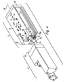
- the electric linear drive designated overall by reference numeral 1, comprises a working unit 2 and a motor module 3 detachably coupled thereto. These two components are arranged successively in the direction of an imaginary mounting axis 4 indicated by dash-dotted lines. The latter simultaneously forms the longitudinal axis of the linear drive. 1
- the working unit 2 contains a designated for better distinction as a main housing 5 elongated housing whose longitudinal axis 6 coincides with the mounting axis 4.
- a main housing 5 elongated housing whose longitudinal axis 6 coincides with the mounting axis 4.
- a main housing 5 elongated housing whose longitudinal axis 6 coincides with the mounting axis 4.
- a tapping part 12 is mounted linearly adjustable so that it can perform relative to the main housing 5 by a double arrow marked, reciprocating linear motion 13. The direction of movement is rectified with the longitudinal axis 6.
- the motor module 3 is attached to the back of the main housing 5 and includes an electric motor 14, which via the Spindle drive 8 is in operative connection with the tapping part 12, so that from the output from the electric motor 14 rotational movement for the output member 12 desired linear motion 13 is derived.
- fastening means 15 of any kind are provided, via which any component can be attached, which is to be adjusted linearly, for example, a part of a machine or a gripper used for handling purposes.
- the tapping part 12 is formed like a slide in the embodiment and slidably mounted along the main housing 5 along with the interposition of suitable linear guide means 16.
- a yoke portion 17 of the Abgriffsteils 12 protrudes in front of the front end face 18 of the main housing 5 in one of the front opening provided there 22 of the receptacle 7 upstream region.
- the spindle drive 8 has two spaced apart front and rear bearing parts 23a, 23b, which are fixed in the interior of the receptacle 7, wherein the front bearing part 23a in the region of the front opening 22 and the rear bearing part 23b in the region of the rear end face 24 of the main housing 5 out opening rear opening 25 of the receptacle 7 is placed. Between the two bearing parts 23a, 23b extending in the manner of a threaded rod-like input part 26 of the spindle drive 8, which is in each case rotatably mounted in the two bearing parts 23a, 23b. By appropriate design of at least one of these two bearings is also ensured that the input part 26 is fixed immovably in the longitudinal direction.
- the motor module 3 is attached with an end-face installation surface 32 to the rear end face 24 of the main housing 5 of the working unit 2.
- the installation surface 32 is located on a for better distinction as a module housing 33 designated housing of the motor module 3, in which the electric motor 14, in particular in the manner of a cartridge, housed.
- the assembly of the motor module 3 on the main housing 5 is carried out by applying in the direction of the mounting axis 4 in the context of an illustrated by an arrow Ansetzschi 34.
- the removal of the motor module 3 from the main body 5 is done by a movement in the opposite direction.
- the attachment of the motor module 3 to the main housing 5 is a plug-in operation.
- complementary first and second plug centering means 35a, 35b engage each other transversely to the mounting axis 4 in a form-fitting manner. In this way, the relative position of the main housing 5 and motor module 3 is defined transversely to the longitudinal axis 6 of the main housing 5.
- the first plug centering means 35a associated with the main housing 5 are preferably formed by a section of the rear bearing part 23b projecting beyond the rear end face 24 of the main housing 5.
- This section has at least partially a substantially cylindrical outer contour, which matingly engages in a complementary recess 36 of the module housing 33 which is open towards the installation surface 32 and which represents the second insertion centering means 35b.
- At least the rear bearing part 23b is screwed into the receptacle 7.
- the peripheral surface of the above the main housing 5 projecting portion of the rear bearing portion 23b at diametrically opposite locations, each with a flat 37 is provided. Even a polygonal contour, for example as a hexagon, would be conceivable.
- the attached to the main housing 5 and in particular infected motor module 3 is axially locked by at least one mounting screw 37 in the scheduled position so that it can not be removed in the direction of the mounting axis 4.
- the fastening screws 37 thus have the purpose of ensuring the axial cohesion of the main housing 5 and engine module 3.
- the fastening screws 37 are released, so that the motor module 3 can be removed.
- the fastening screws 37 can also fulfill an anti-rotation function between the motor module 3 and the drive unit 2.
- each fastening screw 37 passes through the module housing 33, on which it is supported by a head 38, and is detachably screwed into a threaded bore 39 of the main housing 5 open to the rear end face 24.
- a pure plug-in coupling 41 is provided for torque coupling of the input part 26 of the spindle drive 8 with the electric motor 14.
- the elements to be coupled can with a mere mating operation are engaged so that the desired rotational drive is achieved.
- This plug-in procedure is identical to the Ansetzschi 34 of the motor module 3.
- the release of the clutch engagement is done, again independently, when removing the motor module 3 in the direction of the mounting axis. 4
- the plug-in coupling 41 is formed directly by a gear transmission 43. To this end, it contains a rotatably connected to the input part 26 of the spindle drive 8 first transmission gear 44 and a drivingly coupled to the rotatably driven member 46 second transmission gear 45.
- the first transmission gear 44 is arranged coaxially with the input part 26, wherein its axis of rotation 47 is the same as the mounting axis 4 is aligned. The latter also applies to the axis of rotation 48 of the second transmission gear 45.
- the two transmission gears 44, 45 are expediently designed as so-called straight-toothed spur gears, in which the teeth sit on the radially oriented outer circumference. Further, by the axes of rotation 47, 48 are arranged so that they are parallel offset from each other, results in a manufactured clutch engagement a state in which the two gear wheels 44, 45 are arranged in the direction of the mounting axis 4 at the same height side by side.
- the first transmission gear 44 protrudes from the rear over the main housing 5, wherein it is also upstream of the first insertion centering means 35a.
- the second transmission gear 45 is seated in a gear housing 51 forming a section of the module housing 33, wherein the corresponding receiving space of the gear housing 51 is accessible via the recess 36.
- a reverse arrangement is also possible. If the motor module 3 is attached to the main housing 5 while the attachment movement 34 is being executed, the first transmission gearwheel 44 emerges through the recess 36 into the gear housing 51, wherein its toothing is plugged onto the toothing of the second gear wheel 45, so that the two gear teeth 44, 45 mesh according to FIG. 3 at one point of its circumference.
- the motor module 3 can be installed and uninstalled at any such relative position. Thus, for example, it is possible to replace the motor module 3 in the event of a defect without having to remove the working unit 2 from the place of use and while maintaining the instantaneous position of the tapping part 12.
- the output speed of the electric motor can be under-or translate as needed and thereby specify the dependent of the speed of the electric motor 14 speed of the second transmission gear 45.
- the intermediate gear 52 is preferably a planetary gear.
- the second transmission gear 45 is expediently arranged coaxially with the output part 46 of the electric motor 14.
- the two gear wheels 44, 45 are arranged laterally offset from each other, even a relatively large transverse dimensions exhibiting electric motor 14 can still be accommodated in the module housing 33, that there is the possibility by the motor module 3 and the main housing 5 in a common plane to define lying mounting surface 53, via which the linear drive can be fixed to a support structure.
- the entire spindle drive 8 is expediently designed as a uniformly manageable module, which can be used as a structural unit in the receptacle 7 and can also be removed again if necessary.
- the linear drive can be quickly converted if necessary, for example, to a spindle drive 8 with greater or lesser thread pitch.
- the assembly of the entire linear drive proves to be particularly simple due to this modular design.
- the required for the operation of the electric motor 14 electrical energy and actuation signals can be fed via a provided on the module housing 33 electromechanical interface 54. At this interface, moreover, position signals can be tapped, which provides an arranged in the module housing 33, not shown encoder in response to the rotational movement and / or rotational position of the output member 46 of the electric motor 14. In this way, an indirect detection of the position of the embodiment designed as a slide body tapping part 12 is possible.
Abstract
Description
Die Erfindung betrifft einen elektrischen Linearantrieb, mit einem Hauptgehäuse, an dem ein den Abgriff einer Linearbewegung ermöglichendes Abgriffsteil linear verstellbar gelagert ist, das antriebsmäßig mit dem Ausgangsteil eines in dem Hauptgehäuse angeordneten Spindeltriebes gekoppelt ist, dessen drehbares Eingangsteil über eine Kupplung mit einem rückseitig an dem Hauptgehäuse angeordneten Elektromotor in Antriebsverbindung steht.The invention relates to an electric linear drive, with a main housing, on which a tapping of a linear movement enabling tap is mounted linearly adjustable, which is drivingly coupled to the output part of a arranged in the main housing spindle drive whose rotatable input part via a coupling with a back to the Main housing arranged electric motor is in drive connection.
Ein aus der US 5676016 oder der EP-0726118-A bekannter elektrischer Linearantrieb dieser Art verfügt über ein Hauptgehäuse, in dem ein Spindeltrieb untergebracht ist, der mit einem schlittenartig ausgebildeten Abgriffsteil gekoppelt ist. Wird das spindelartige Eingangsteil des Spindeltriebes zu einer Drehbewegung veranlasst, führt das Ausgangsteil des Spindeltriebes eine Linearbewegung aus, die sich an dem Abgriffsteil abgreifen lässt. Die Drehbewegung des Eingangsteils wird durch einen an der Rückseite des Hauptgehäuses angeordneten Elektromotor hervorgerufen, dessen Abtriebsteil über eine Kupplung mit dem Eingangsteil des Spindeltriebes drehfest verbunden ist.A known from US 5676016 or EP-0726118-A electric linear drive of this type has a main housing in which a spindle drive is housed, which is coupled to a slide-like tapping part. If the spindle-like input part of the spindle drive causes a rotational movement, the output part of the spindle drive executes a linear movement, which can be tapped off at the tapping part. The rotational movement of the input part is caused by a arranged at the rear of the main housing electric motor, the output part is rotatably connected via a coupling with the input part of the spindle drive.
Der bekannte Linearantrieb lässt sich nur dadurch sinnvoll zusammenbauen, dass der Elektromotor gemeinsam mit dem vorab daran angebrachten Spindeltrieb installiert wird. Entsprechendes gilt für eine Demontage im Reparaturfall, weil die Kupplung zum Entfernen der den axialen Zusammenhalt gewährleistenden Querstifte nicht ohne weiteres zugänglich ist.The well-known linear drive can be assembled only meaningful that the electric motor is installed together with the previously attached thereto spindle drive. The same applies to a disassembly in case of repair, because the coupling for removing the axial cohesion ensuring cross pins is not readily accessible.
Es ist daher die Aufgabe der vorliegenden Erfindung, einen elektrischen Linearantrieb der eingangs genannten Art zu schaffen, dessen Montage und Demontage einfacher vonstatten geht.It is therefore the object of the present invention to provide an electric linear drive of the type mentioned, whose assembly and disassembly is easier.
Zur Lösung dieser Aufgabe ist vorgesehen, dass die Kupplung als reine Steckkupplung ausgeführt und unmittelbar von einem Zahnradgetriebe gebildet ist, das ein mit dem Eingangsteil des Spindeltriebes drehfest verbundenes, bezüglich des Hauptgehäuses ortsfest fixiertes erstes Getriebezahnrad und ein mit dem Abtriebsteil des Elektromotors verbundenes zweites Getriebezahnrad enthält, wobei das zweite Getriebezahnrad gemeinsam mit dem Elektromotor Bestandteil eines Motormoduls ist, das unabhängig von der momentan zwischen dem Eingangsteil und dem Ausgangsteil des Spindeltriebes eingenommenen Relativposition, und bei gleichzeitig selbsttätigem Herstellen bzw. Aufheben des Zahnradeingriffes zwischen den beiden Getriebezahnrädern, rückseitig am Hauptgehäuse ansetzbar und abnehmbar ist.To achieve this object, it is provided that the coupling is designed as a pure plug-in coupling and formed directly by a toothed gear, which rotatably connected to the input part of the spindle drive, fixed with respect to the main housing fixed first gear and a gear connected to the output part of the electric motor second gear , Wherein the second transmission gear together with the electric motor is part of a motor module, irrespective of the currently occupied between the input part and the output part of the spindle drive relative position, and at the same time making or canceling the gear engagement between the two gear wheels, attachable to the back of the main housing and is removable.
Auf diese Weise kann der Elektromotor unabhängig vom Spindeltrieb installiert und deinstalliert werden. Die rein als Steckkupplung ausgestaltete Kupplung erfordert keine gegenseitige Arretierung der miteinander zu kuppelnden Elemente, sodass beim Ansetzen und Abnehmen des den Elektromotor aufweisenden Motormoduls automatisch der Kupplungseingriff hergestellt bzw. aufgehoben wird. Dies ist nicht nur bei der Erstmontage und in Servicefällen von Vorteilen. Auch bei einer notwendigen Umrüstung des Linearantriebes auf eine andere Leistung oder eine andere Übersetzung erweist sich die problemlose Austauschmöglichkeit als vorteilhaft. Schließlich kann durch die Ausgestaltung der Steckkupplung als Zahnradgetriebe die für die Kupplungsmaßnahmen erforderliche Baulänge bei Bedarf reduziert werden, da die miteinander in Eingriff stehenden Getriebezahnräder quer zur Längsachse des Linearantriebes nebeneinander angeordnet werden können.In this way, the electric motor can be installed and deinstalled independently of the spindle drive. The coupling designed purely as a plug-in coupling does not require mutual locking of the elements to be coupled to one another, so that the clutch engagement is automatically established or canceled when the electric motor is attached to and removed from the motor module. This is not only beneficial for initial assembly and servicing. Even with a necessary conversion of the linear drive to a different performance or another translation, the problem-free replacement option proves to be advantageous. Finally, the length required for the coupling measures length can be reduced if necessary by the configuration of the plug-in coupling as a gear transmission, since the meshing gear wheels can be arranged transversely to the longitudinal axis of the linear drive side by side.
Vorteilhafte Weiterbildungen der Erfindung gehen aus den Unteransprüchen hervor.Advantageous developments of the invention will become apparent from the dependent claims.
Die beiden Getriebezahnräder sind zweckmäßigerweise als am Außenumfang verzahnte Stirnräder ausgeführt, die parallel versetzt zueinander angeordnet sind und deren Drehachsen in Richtung einer gedachten Montageachse ausgerichtet sind, entlang der die Motoreinheit beim Ansetzen bzw. Abnehmen an das bzw. von dem Hauptgehäuse verlagert wird. Auf diese Weise gelangen die beiden Getriebezahnräder auf besonders einfache Weise unmittelbar beim Ansetz- und Abnehmvorgang in bzw. außer Eingriff miteinander. Besonders zweckmäßig ist dabei eine Ausgestaltung der Stirnräder mit einer umfangsseitigen Geradverzahnung, wenngleich prinzipiell auch eine schrägverzahnte Bauform möglich wäre.The two gear wheels are expediently designed as spur gears toothed on the outer circumference, which are arranged offset parallel to each other and whose axes of rotation are aligned in the direction of an imaginary mounting axis along which the motor unit is displaced during attachment or removal to or from the main housing. In this way, the two transmission gears arrive in a particularly simple manner immediately during the piecing and removal process in or out of engagement with each other. Particularly useful is an embodiment of the spur gears with a circumferential spur toothing, although in principle a helical design would be possible.
Um beim Ansetzen des Motormoduls automatisch die korrekte Position zu erhalten, ist es von Vorteil, wenn dem Hauptgehäuse und dem Motormodul zueinander komplementäre Steckzentriermittel zugeordnet sind, die beim Ansetzen des Motormoduls an das Hauptgehäuse miteinander in Steckeingriff gelangen.In order to automatically obtain the correct position when attaching the motor module, it is advantageous if the main housing and the motor module mutually complementary Steckzentriermittel are associated with each other, which get in mating engagement with the attachment of the motor module to the main housing.
Damit sich das Motormodul bei Bedarf sehr rasch montieren und demontieren lässt, ist es im an das Hauptgehäuse angesteckten Zustand zweckmäßigerweise lediglich durch eine oder mehrere Befestigungsschrauben arretiert. Sind die Befestigungsschrauben gelöst, lässt sich das Motormodul ohne weiteres vom Hauptgehäuse abziehen.So that the motor module can be assembled and disassembled very quickly if necessary, it is expediently locked in the state which is connected to the main housing only by one or more fastening screws. Once the fixing screws have been loosened, the motor module can be easily removed from the main housing.
Der Elektromotor kann als Baueinheit in einem Modulgehäuse des Motormoduls untergebracht sein. Er ist insbesondere lösbar eingesetzt, sodass bei Bedarf ein Austausch möglich ist, beispielsweise im Defektfalle oder zur Umrüstung auf eine andere Motorleistung.The electric motor can be accommodated as a structural unit in a module housing of the motor module. It is used in particular detachable, so that if necessary, an exchange is possible, for example in the event of a defect or for conversion to a different engine performance.
Im Zusammenhang mit der Erfindung können alternativ mehrere Motormodule bereitgestellt werden, die sich in der am zweiten Getriebezahnrad abgreifbaren Drehzahl unterscheiden und die wahlweise an einem Hauptgehäuse installierbar sind, um den Spindeltrieb mit - dem jeweiligen Anwendungsfall entsprechend - unterschiedlichen Drehzahlen anzutreiben. Hier wäre es beispielsweise möglich, die mehreren Motormodule mit unterschiedlichen Elektromotoren auszustatten. Eine wesentlich einfachere Lösung sieht vor, auf identische Elektromotoren zurückzugreifen, jedoch zwischen dem Elektromotor und dem zweiten Getriebezahnrad ein zur Unter- oder Übersetzung dienendes Zwischengetriebe vorzusehen, das bei entsprechender Auslegung die Drehzahl des Elektromotors in die gewünschte Drehzahl des zweiten Getriebezahnrades umsetzt. Das Zwischengetriebe ist insbesondere als Planetengetriebe ausgeführt.In connection with the invention, a plurality of motor modules can alternatively be provided, which differ in the tappable at the second transmission gear speed and which can be optionally installed on a main housing to drive the spindle drive - according to the particular application - different speeds. Here it would be possible, for example, to equip the several motor modules with different electric motors. A much simpler solution provides to resort to identical electric motors, however, to provide between the electric motor and the second gear gear for under- or translation serving intermediate gear, which converts the rotational speed of the electric motor in the desired speed of the second gear wheel with a corresponding design. The intermediate gear is designed in particular as a planetary gear.
Das Hauptgehäuse, das Abgriffsteil und der Spindeltrieb.können zu einer Arbeitseinheit zusammengefasst sein, wobei der Spindeltrieb als Modul ausgeführt ist, das lösbar in einer Aufnahme des Hauptgehäuses fixiert ist. Der Spindeltrieb kann somit als Ganzes installiert und deinstalliert werden, was zum einen Reparaturen erleichtert und zum anderen eine leichte Umrüstung des Linearantriebes auf beispielsweise andere Gewindesteigungen oder auf andere Bauarten des Spindeltriebes ermöglicht. Auf diese Weise kann beispielsweise eine Ausstattung mit wahlweise einem Kugelgewindetrieb oder einem Gleitgewindetrieb vorgenommen werden.The main housing, the tapping part and the Spindeltrieb.können be summarized to a work unit, wherein the spindle drive is designed as a module which is releasably fixed in a receptacle of the main housing. The spindle drive can thus be installed and uninstalled as a whole, which facilitates repairs and on the other hand allows easy conversion of the linear drive to other thread pitches or other types of spindle drive. In this way, for example, an equipment with either a ball screw or a sliding screw can be made.
Bei Bedarf kann das Motormodul mit einem Encoder ausgestattet sein, der die Drehbewegung des Elektromotors auswertet und somit quasi als Wegmesssystem zur Positionserfassung des linear verstellbaren Abgriffsteils eingesetzt werden kann.If required, the motor module can be equipped with an encoder that evaluates the rotational movement of the electric motor and thus can be used quasi as a displacement measuring system for detecting the position of the linearly adjustable tapping part.
Nachfolgend wird die Erfindung anhand der beiliegenden Zeichnung näher erläutert. In dieser zeigen:
- Fig. 1
- eine bevorzugte Bauform des erfindungsgemäßen elektrischen Linearantriebs in einer perspektivischen Darstellung,
- Fig. 2
- den Linearantrieb aus Fig. 1 in einer Seitenansicht gemäß Pfeil IIa, wobei der Bereich der Steckkupplung im Sinne der Schnittlinie IIb-IIb aus Fig. 3 aufgebrochen dargestellt ist,
- Fig. 3
- einen Querschnitt durch den Linearantrieb gemäß Schnittlinie III-III aus Fig. 2 und
- Fig. 4
- den Linearantrieb aus Fig. 1 im abgenommenen Zustand des Motormoduls.
- Fig. 1
- a preferred design of the electric linear drive according to the invention in a perspective view,
- Fig. 2
- 1 in a side view according to arrow IIa, wherein the region of the plug-in coupling in the sense of section line IIb-IIb of FIG. 3 is shown broken away,
- Fig. 3
- a cross section through the linear drive according to section line III-III of Fig. 2 and
- Fig. 4
- the linear drive of Fig. 1 in the removed state of the motor module.
Der insgesamt mit Bezugsziffer 1 bezeichnete elektrische Linearantrieb umfasst eine Arbeitseinheit 2 und ein lösbar mit dieser gekoppeltes Motormodul 3. Diese beiden Komponenten sind in Richtung einer gedachten, strichpunktiert angedeuteten Montageachse 4 aufeinanderfolgend angeordnet. Letztere bildet gleichzeitig die Längsachse des Linearantriebes 1.The electric linear drive, designated overall by reference numeral 1, comprises a
Die Arbeitseinheit 2 enthält ein zur besseren Unterscheidung als Hauptgehäuse 5 bezeichnetes längliches Gehäuse, dessen Längsachse 6 mit der Montageachse 4 zusammenfällt. In einer das Hauptgehäuse 5 in Längsrichtung durchziehenden Aufnahme 7 ist ein als einheitlich handhabbares Modul ausgeführter Spindeltrieb 8 in austauschbarer Weise untergebracht. Außen am Hauptgehäuse 5 ist ein Abgriffsteil 12 linear verstellbar gelagert, sodass es relativ zum Hauptgehäuse 5 eine durch einen Doppelpfeil markierte, hin und her gehende Linearbewegung 13 ausführen kann. Die Bewegungsrichtung ist mit der Längsachse 6 gleichgerichtet.The working
Das Motormodul 3 ist rückseitig an das Hauptgehäuse 5 angesetzt und beinhaltet einen Elektromotor 14, der über den Spindeltrieb 8 mit dem Abgriffsteil 12 in Wirkverbindung steht, sodass aus der vom Elektromotor 14 ausgegebenen Rotationsbewegung die für das Abtriebsteil 12 gewünschte Linearbewegung 13 abgeleitet wird.The
An dem Abgriffsteil 12 sind Befestigungsmittel 15 beliebiger Art vorgesehen, über die sich eine beliebige Komponente anbringen lässt, die linear verstellt werden soll, beispielsweise ein Teil einer Maschine oder ein zu Handhabungszwecken eingesetzter Greifer.On the tapping
Das Abgriffsteil 12 ist beim Ausführungsbeispiel schlittenartig ausgebildet und unter Zwischenschaltung geeigneter Linearführungsmittel 16 längsseits am Hauptgehäuse 5 verschiebbar gelagert. Ein Jochabschnitt 17 des Abgriffsteils 12 ragt vor die vordere Stirnfläche 18 des Hauptgehäuses 5 in einen der dort vorgesehenen vorderen Öffnung 22 der Aufnahme 7 vorgelagerten Bereich.The tapping
Der Spindeltrieb 8 verfügt über zwei zueinander beabstandete vordere und rückwärtige Lagerteile 23a, 23b, die im Innern der Aufnahme 7 fixiert sind, wobei das vordere Lagerteil 23a im Bereich der vorderen Öffnung 22 und das rückwärtige Lagerteil 23b im Bereich der zur rückwärtigen Stirnfläche 24 des Hauptgehäuses 5 ausmündenden rückwärtigen Öffnung 25 der Aufnahme 7 platziert ist. Zwischen den beiden Lagerteilen 23a, 23b erstreckt sich das nach Art einer Gewindespindel ausgeführte stangenartige Eingangsteil 26 des Spindeltriebes 8, das in den beiden Lagerteilen 23a, 23b jeweils drehbar gelagert ist. Durch entsprechende Ausgestaltung mindestens einer dieser beiden Lagerungen ist außerdem dafür gesorgt, dass das Eingangsteil 26 in Längsrichtung unbeweglich fixiert ist.The
Auf dem spindelartigen Eingangsteil 26 sitzt ein nach Art einer Mutter ausgebildetes Ausgangsteil 27 des Spindeltriebes, das über mindestens ein sich axial erstreckendes Koppelelement 28, welches im Bereich der vorderen Öffnung 22 aus dem Hauptgehäuse 5 herausragt, mit dem Jochabschnitt 17 axial bewegungsgekoppelt ist. Das Ausgangsteil 27 ist drehfest fixiert, beispielsweise durch eine entsprechende Verbindung mit dem Jochabschnitt 17, und steht mit dem Eingangsteil 26 in Schraubeingriff. Somit führt eine Rotation des Eingangsteils 26 entsprechend der gewählten Drehrichtung zu einer Linearbewegung des Ausgangsteils 27 relativ zum Eingangsteil 26 in der einen oder anderen Richtung, was aufgrund der geschilderten Bewegungskopplung die oben schon erläuterte Linearbewegung 13 des Abgriffteils 12 zur Folge hat.On the spindle-
Das Motormodul 3 ist mit einer stirnseitigen Installationsfläche 32 an die rückseitige Stirnfläche 24 des Hauptgehäuses 5 der Arbeitseinheit 2 angesetzt. Die Installationsfläche 32 befindet sich an einem zur besseren Unterscheidung als Modulgehäuse 33 bezeichneten Gehäuse des Motormoduls 3, in dem der Elektromotor 14, insbesondere nach Art einer Patrone, untergebracht ist. Die Montage des Motormoduls 3 am Hauptgehäuse 5 erfolgt durch Ansetzen in Richtung der Montageachse 4 im Rahmen einer durch einen Pfeil verdeutlichten Ansetzbewegung 34. Das Abnehmen des Motormoduls 3 vom Hauptgehäuse 5 geschieht durch eine Bewegung in entgegengesetzter Richtung.The
Das Ansetzen des Motormoduls 3 an das Hauptgehäuse 5 ist ein Steckvorgang. Bei diesem Steckvorgang greifen zueinander komplementäre erste und zweite Steckzentriermittel 35a, 35b quer zur Montageachse 4 formschlüssig ineinander. Auf diese Weise ist die Relativposition von Hauptgehäuse 5 und Motormodul 3 quer zur Längsachse 6 des Hauptgehäuses 5 festgelegt.The attachment of the
Bevorzugt sind die dem Hauptgehäuse 5 zugeordneten ersten Steckzentriermittel 35a von einem über die rückwärtige Stirnfläche 24 des Hauptgehäuses 5 vorstehenden Abschnitt des rückwärtigen Lagerteils 23b gebildet. Dieser Abschnitt hat zumindest partiell eine im Wesentlichen zylindrische Außenkontur, die passend in eine zur Installationsfläche 32 hin offene komplementäre Ausnehmung 36 des Modulgehäuses 33 eingreift, die die zweiten Steckzentriermittel 35b repräsentiert.The first plug centering means 35a associated with the main housing 5 are preferably formed by a section of the
Beim Ausführungsbeispiel ist zumindest das rückwärtige Lagerteil 23b in die Aufnahme 7 eingeschraubt. Um hierbei das bequeme Ansetzen eines Schraubwerkzeuges zu ermöglichen, ist die Umfangsfläche des über das Hauptgehäuse 5 vorstehenden Abschnittes des rückwärtigen Lagerteils 23b an sich diametral gegenüberliegenden Stellen mit jeweils einer Abflachung 37 versehen. Auch eine Mehrkantkontur, beispielsweise als Sechskant, wäre denkbar.In the embodiment, at least the
Das an das Hauptgehäuse 5 angesetzte und insbesondere angesteckte Motormodul 3 wird durch mindestens eine Befestigungsschraube 37 in der angesetzten Position axial arretiert, sodass es in Richtung der Montageachse 4 nicht mehr abgenommen werden kann. Die Befestigungsschrauben 37 haben mithin den Zweck, den axialen Zusammenhalt von Hauptgehäuse 5 und Motormodul 3 zu gewährleisten. Um das Motormodul 3 zu entfernen, werden die Befestigungsschrauben 37 gelöst, sodass das Motormodul 3 abgezogen werden kann. Die Befestigungsschrauben 37 können auch eine Verdrehsicherungsfunktion zwischen dem Motormodul 3 und der Antriebseinheit 2 erfüllen.The attached to the main housing 5 and in particular
Um diese Arretierfunktion zu erfüllen, reichen in der Regel eine, höchstens zwei Befestigungsschrauben 37 aus. Jede Befestigungsschraube 37 durchsetzt das Modulgehäuse 33, an dem sie sich mit einem Kopf 38 abstützt, und ist in eine zur rückwärtigen Stirnfläche 24 offene Gewindebohrung 39 des Hauptgehäuses 5 lösbar eingeschraubt.In order to fulfill this locking function, usually one, at most two
Zur drehmomentmäßigen Kupplung des Eingangsteils 26 des Spindeltriebes 8 mit dem Elektromotor 14 ist eine reine Steckkupplung 41 vorgesehen. Die zu kuppelnden Elemente können mit einem bloßen Steckvorgang so in Eingriff gebracht werden, dass die gewünschte Drehmitnahme erreicht wird. Dieser Steckvorgang ist identisch mit der Ansetzbewegung 34 des Motormoduls 3. Das Lösen des Kupplungeingriffes geschieht, wiederum selbstständig, beim Abnehmen des Motormoduls 3 in der Richtung der Montageachse 4.For torque coupling of the
In vorteilhafter Weise ist die Steckkupplung 41 unmittelbar von einem Zahnradgetriebe 43 gebildet. Hierzu enthält sie ein mit dem Eingangsteil 26 des Spindeltriebes 8 drehfest verbundenes erstes Getriebezahnrad 44 und ein mit dem rotativ angetriebenen Abtriebsteil 46 antriebsmäßig gekoppeltes zweites Getriebezahnrad 45. Das erste Getriebezahnrad 44 ist koaxial zu dem Eingangsteil 26 angeordnet, wobei seine Drehachse 47 gleich wie die Montageachse 4 ausgerichtet ist. Letzteres gilt auch für die Drehachse 48 des zweiten Getriebezahnrades 45.Advantageously, the plug-in coupling 41 is formed directly by a gear transmission 43. To this end, it contains a rotatably connected to the
Die beiden Getriebezahnräder 44, 45 sind zweckmäßigerweise als sogenannte geradverzahnte Stirnräder ausgeführt, bei denen die Verzahnungen am radial orientierten Außenumfang sitzen. Indem ferner die Drehachsen 47, 48 so angeordnet sind, dass sie parallel versetzt zueinander verlaufen, ergibt sich bei hergestelltem Kupplungseingriff ein Zustand, bei dem die beiden Getriebezahnräder 44, 45 in Richtung der Montageachse 4 auf gleicher Höhe nebeneinander angeordnet sind.The two transmission gears 44, 45 are expediently designed as so-called straight-toothed spur gears, in which the teeth sit on the radially oriented outer circumference. Further, by the axes of
Das erste Getriebezahnrad 44 steht rückseitig über das Hauptgehäuse 5 vor, wobei es auch den ersten Steckzentriermitteln 35a vorgelagert ist. Das zweite Getriebezahnrad 45 sitzt in einem einen Abschnitt des Modulgehäuses 33 bildenden Getriebegehäuse 51, wobei der entsprechende Aufnahmeraum des Getriebegehäuses 51 über die Ausnehmung 36 zugänglich ist. Auch eine umgekehrte Anordnung ist allerdings möglich. Wird das Motormodul 3 unter Ausführung der Ansetzbewegung 34 an das Hauptgehäuse 5 angesetzt, taucht das erste Getriebezahnrad 44 durch die Ausnehmung 36 hindurch in das Getriebegehäuse 51 ein, wobei seine Verzahnung auf die Verzahnung des zweiten Getriebezahnrads 45 aufgesteckt wird, sodass die beiden Getriebezahnräder 44, 45 gemäß Fig. 3 an einer Stelle ihres Umfanges miteinander kämmen.The
Dieser Ansetzvorgang reicht aus, um den Kupplungseingriff herzustellen. Beim Ansetzen des Motormoduls 3 wird also selbsttätig bzw. automatisch der die Drehmomentübertragung garantierende Zahnradeingriff hergestellt.This attachment process is sufficient to produce the clutch engagement. When attaching the
Umgekehrt wird der Zahnradeingriff wiederum selbsttätig aufgehoben, wenn das Motormodul 3 entgegen der Ansetzrichtung 34 vom Hauptgehäuse 5 abgenommen wird.Conversely, the gear engagement is in turn automatically canceled when the
Da das erste Getriebezahnrad 44 unabhängig von der momentan zwischen dem Eingangsteil 26 und dem Ausgangsteil 27 eingenommenen Relativposition eine gleichbleibende, das heißt ortsfest fixierte Lage bezüglich des Hauptgehäuses 5 einnimmt, kann das Motormodul 3 bei jeder derartigen Relativposition installiert und deinstalliert werden. Es besteht also beispielsweise die Möglichkeit, das Motormodul 3 im Falle eines Defekts auszutauschen, ohne die Arbeitseinheit 2 vom Einsatzort entfernen zu müssen und unter Beibehaltung der momentanen Position des Abgriffsteils 12.Since the
In dem Modulgehäuse 33 kann zwischen dessen Abtriebsteil 46 und dem zweiten Getriebezahnrad 45 ein schematisch angedeutetes Zwischengetriebe 52 sitzen. Mit diesem lässt sich die Abtriebsdrehzahl des Elektromotors nach Bedarf unter- oder übersetzen und dadurch die von der Drehzahl des Elektromotors 14 abhängige Drehzahl des zweiten Getriebezahnrades 45 vorgeben. Bei dem Zwischengetriebe 52 handelt es sich vorzugsweise um ein Planetengetriebe. Durch Bereitstellung mehrerer Motormodule 3 mit unterschiedlichen Zwischengetrieben 52 können somit über den Austausch des Motormoduls 3 verschiedene Drehzahlüber- bzw. -untersetzungen nach Bedarf vorgegeben werden.In the
Das zweite Getriebezahnrad 45 ist zweckmäßigerweise koaxial zum Abtriebsteil 46 des Elektromotors 14 angeordnet. Indem jedoch die beiden Getriebezahnräder 44, 45 seitlich versetzt zueinander angeordnet sind, kann auch ein relativ große Querabmessungen aufweisender Elektromotor 14 noch so in dem Modulgehäuse 33 untergebracht werden, dass die Möglichkeit besteht, durch das Motormodul 3 und das Hauptgehäuse 5 eine in einer gemeinsamen Ebene liegende Montagefläche 53 zu definieren, über die der Linearantrieb an einer Tragstruktur festlegbar ist.The
Der gesamte Spindeltrieb 8 ist zweckmäßigerweise als ein einheitlich handhabbares Modul ausgebildet, das sich als Baueinheit in die Aufnahme 7 einsetzen und bei Bedarf auch wieder entfernen lässt. Dadurch kann der Linearantrieb bei Bedarf rasch umgerüstet werden, beispielsweise auf einen Spindeltrieb 8 mit größerer oder geringerer Gewindesteigung. Außerdem erweist sich die Montage des gesamten Linearantriebes durch diese Modulbauweise als besonders einfach.The
Die für den Betrieb des Elektromotors 14 erforderliche elektrische Energie und Betätigungssignale können über eine am Modulgehäuse 33 vorgesehene elektromechanische Schnittstelle 54 eingespeist werden. An dieser Schnittstelle können überdies Positionssignale abgegriffen werden, die ein im Modulgehäuse 33 angeordneter, nicht näher dargestellter Encoder in Abhängigkeit von der Drehbewegung und/oder Drehposition des Abtriebsteils 46 des Elektromotors 14 liefert. Auf diese Weise ist eine indirekte Erfassung der Position des beim Ausführungsbeispiel als Schlittenkörper ausgebildeten Abgriffteils 12 möglich.The required for the operation of the
Claims (16)
- Electric linear drive with a main housing (5) on which a takeoff part (12) permitting the takeoff of a linear movement is mounted for linear traverse and coupled to the output part (27) of a spindle drive (8) located in the main housing (5), the rotatable input part (26) of which is drive-connected to an electric motor (14) located at the rear of the main housing (5) via a clutch, characterised in that the clutch is designed as a pure plug-in clutch (41) directly represented by a gear train (43) comprising a first gear wheel (44) non-rotatably connected to the input part (26) of the spindle drive (8) and located in a fixed position relative to the main housing (5) and a second gear wheel (45) connected to the output part (46) of the electric motor (14), wherein the first gear wheel (45) together with the electric motor (14) is part of a motor module (3) which can be fitted to and removed from the rear of the main housing (5) independent of the relative positions currently adopted by the input part (26) and the output part (27) of the spindle drive (8) while simultaneously and automatically establishing or cancelling the engagement between the two gear wheels (44, 45).
- Linear drive according to claim 1, characterised in that the two gear wheels (44, 45) are designed as spur gears with axes of rotation (47, 48) extending parallel and offset to one another and aligned to an imaginary mounting axis (4) along which the motor module (3) has to be displaced during the fitting and removal process.
- Linear drive according to claim 2, characterised in that the mounting axis (4) coincides with the longitudinal axis (6) of the main housing (5).
- Linear drive according to claim 2 or 3, characterised in that the two gear wheels (44, 45) are designed as straight-cut spur gears.
- Linear drive according to any of claims 1 to 4, characterised in that the first gear wheel (44) projects beyond the rear of the main housing (5) and, in the fitted state of the motor module (3), dips into a gear housing (51) in which the second gear wheel (45) is located.
- Linear drive according to any of claims 1 to 5, characterised by complementary plug-in centring means (35a, 35b) assigned to the main housing (5) and the motor module (3), which, when fitted to one another, engage one another to predetermine the relative positions of the two gear wheels (44, 45).
- Linear drive according to claim 6, characterised in that the plug-in centring means (35a, 35b) are coaxial with the axis of rotation (47) of the first gear wheel (44).
- Linear drive according to claim 6 or 7, characterised in that the plug-in centring means (35a) assigned to the main housing (5) are represented by a bearing part (23b) of the spindle drive (8), which projects beyond the rear of the main housing (5) and is located in a fixed position relative to the main housing (5).
- Linear drive according to any of claims 1 to 8, characterised in that the motor module (3) can be fitted to the main housing (5) and secured in the fitted position by at least one mounting screw (37).
- Linear drive according to any of claims 1 to 9, characterised in that the motor module (3) incorporates a module housing (33) into which the electric motor (14) is, in particular releasably, installed.
- Linear drive according to claim 10, characterised in that an intermediate gear (52) designed in particular as a planetary gear is provided between the electric motor (14) and the second gear wheel (45).
- Linear drive according to any of claims 1 to 11, characterised in that the main housing (5), the takeoff part (12) and the spindle drive (8) are combined to form an operating unit (2).
- Linear drive according to claim 12, characterised in that the spindle drive (8) is designed as a module releasably located in a location (7) of the main housing (5).
- Linear drive according to any of claims 1 to 13, characterised in that the output part (27) of the spindle drive (8) is designed as a nut and runs on the input part (26) designed as a threaded spindle, being coupled for movement with the takeoff part (12).
- Linear drive according to any of claims 1 to 14, characterised in that the takeoff part (12) is a slide body movable relative to the main housing (5) by way of linear guide means (16).
- Linear drive according to any of claims 1 to 15, characterised in that the motor module (3) and the main housing (5) define a mounting surface (53) lying in a common plane.
Priority Applications (4)
| Application Number | Priority Date | Filing Date | Title |
|---|---|---|---|
| AT04002750T ATE327077T1 (en) | 2004-02-07 | 2004-02-07 | ELECTRIC LINEAR DRIVE WITH A PLUG-IN COUPLING BETWEEN A SPINDLE DRIVE AND A MOTOR MODULE |
| EP04002750A EP1566238B1 (en) | 2004-02-07 | 2004-02-07 | Electric linear drive with a plug coupling between a driving screw and a drive module |
| DE502004000621T DE502004000621D1 (en) | 2004-02-07 | 2004-02-07 | Electric linear drive with a plug-in coupling between a spindle drive and a motor module |
| US11/050,106 US7199494B2 (en) | 2004-02-07 | 2005-02-03 | Electric linear actuator |
Applications Claiming Priority (1)
| Application Number | Priority Date | Filing Date | Title |
|---|---|---|---|
| EP04002750A EP1566238B1 (en) | 2004-02-07 | 2004-02-07 | Electric linear drive with a plug coupling between a driving screw and a drive module |
Publications (2)
| Publication Number | Publication Date |
|---|---|
| EP1566238A1 EP1566238A1 (en) | 2005-08-24 |
| EP1566238B1 true EP1566238B1 (en) | 2006-05-24 |
Family
ID=34707296
Family Applications (1)
| Application Number | Title | Priority Date | Filing Date |
|---|---|---|---|
| EP04002750A Expired - Lifetime EP1566238B1 (en) | 2004-02-07 | 2004-02-07 | Electric linear drive with a plug coupling between a driving screw and a drive module |
Country Status (4)
| Country | Link |
|---|---|
| US (1) | US7199494B2 (en) |
| EP (1) | EP1566238B1 (en) |
| AT (1) | ATE327077T1 (en) |
| DE (1) | DE502004000621D1 (en) |
Families Citing this family (6)
| Publication number | Priority date | Publication date | Assignee | Title |
|---|---|---|---|---|
| DE102004017896A1 (en) * | 2004-04-13 | 2005-11-03 | Festo Ag & Co. | Method for producing a driving connection in a linear drive |
| US8636670B2 (en) | 2008-05-13 | 2014-01-28 | The Invention Science Fund I, Llc | Circulatory monitoring systems and methods |
| US9717896B2 (en) | 2007-12-18 | 2017-08-01 | Gearbox, Llc | Treatment indications informed by a priori implant information |
| US20090287120A1 (en) | 2007-12-18 | 2009-11-19 | Searete Llc, A Limited Liability Corporation Of The State Of Delaware | Circulatory monitoring systems and methods |
| ITMI20112202A1 (en) * | 2011-12-02 | 2013-06-03 | Metal Work Spa | CONNECTION ARRANGEMENT OF AT LEAST TWO BODIES, IN PARTICULAR AT LEAST TWO BODIES OF COMPONENTS OF A GROUP OF MECHANICAL AUTOMATION OF MOVEMENTS, WITH A GROUP OF REMOVABLE CONSTRAINTS |
| DE102019104252B3 (en) * | 2019-02-20 | 2020-08-13 | Schaeffler Technologies AG & Co. KG | Linear actuator and construction kit for the production of this linear actuator |
Family Cites Families (16)
| Publication number | Priority date | Publication date | Assignee | Title |
|---|---|---|---|---|
| DE2941500A1 (en) * | 1979-10-12 | 1981-04-30 | Friedrich Deckel AG, 8000 München | SPINDLE DRIVE FOR SLIDING A MACHINE PART ON A BASE |
| US4288182A (en) * | 1980-02-15 | 1981-09-08 | Lasalle Machine Tool, Inc. | Machining apparatus tool feed and retract system |
| GB2092702B (en) * | 1981-02-07 | 1984-07-18 | Tully Engineering Co Ltd | Improvements in or relating to screw and nut actuators |
| DE3236526A1 (en) * | 1982-10-02 | 1984-08-02 | Müller, Arnold, 7312 Kirchheim | LINEAR MOTION DEVICE FOR MACHINES |
| GB8321376D0 (en) * | 1983-08-09 | 1983-09-28 | British Aerospace | Control apparatus |
| US4607180A (en) * | 1983-11-14 | 1986-08-19 | General Dynamics Corporation/Convair Div. | Failure tolerant linear drive mechanism intended for celestial space applications |
| JPH0761587B2 (en) * | 1990-10-25 | 1995-07-05 | テイエチケー株式会社 | Transfer table using ball screw guide unit |
| DE69432192T2 (en) * | 1993-10-12 | 2003-12-04 | Smc Kk | linear actuator |
| TW463449B (en) | 1995-02-10 | 2001-11-11 | Smc Kk | Electric actuator |
| JP3927285B2 (en) * | 1997-07-08 | 2007-06-06 | 日本トムソン株式会社 | Slide device |
| US6101889A (en) * | 1998-01-20 | 2000-08-15 | Thomson Saginaw Ball Screw Company, Llc | Ball screw and nut linear actuator assemblies and methods of constructing and operating them |
| US6174102B1 (en) * | 1998-01-26 | 2001-01-16 | New Focus, Inc. | Modular motion stages utilizing interconnecting elements |
| DE19853942C1 (en) * | 1998-11-24 | 2000-07-13 | Festo Ag & Co | Electric linear actuator |
| DE10009713A1 (en) * | 2000-03-02 | 2001-09-13 | Stefan Thiesbrummel | Feed and delivery module has feature whereby by conical grinding of guide tracks in working area of module a high pretensioning and precision is achieved, while in region of table delivery there is high play in guide |
| WO2002061922A1 (en) * | 2001-01-26 | 2002-08-08 | Tol-O-Matic, Inc. | Electric actuator for rotary and linear motion |
| JP3867519B2 (en) * | 2001-06-08 | 2007-01-10 | 松下電器産業株式会社 | motor |
-
2004
- 2004-02-07 EP EP04002750A patent/EP1566238B1/en not_active Expired - Lifetime
- 2004-02-07 AT AT04002750T patent/ATE327077T1/en not_active IP Right Cessation
- 2004-02-07 DE DE502004000621T patent/DE502004000621D1/en not_active Expired - Lifetime
-
2005
- 2005-02-03 US US11/050,106 patent/US7199494B2/en not_active Expired - Fee Related
Also Published As
| Publication number | Publication date |
|---|---|
| US7199494B2 (en) | 2007-04-03 |
| EP1566238A1 (en) | 2005-08-24 |
| ATE327077T1 (en) | 2006-06-15 |
| US20050179325A1 (en) | 2005-08-18 |
| DE502004000621D1 (en) | 2006-06-29 |
Similar Documents
| Publication | Publication Date | Title |
|---|---|---|
| EP2075395B1 (en) | Actuator for powered closure of a vehicle lock | |
| DE202014011323U1 (en) | Non-coaxial mounted electrical actuator and gearbox | |
| DE3938353C2 (en) | Spindle drive device for generating optional linear and / or rotary movements of the spindle | |
| EP3957441B1 (en) | Blind rivet fixer setting device | |
| WO2004071244A2 (en) | Electromotive linear drive unit | |
| DE19955244A1 (en) | Winding machine has rotator which is equipped with power joint portion driven by portable drive unit | |
| EP2956689B1 (en) | Electrically actuated rotary drive device | |
| EP0050238B1 (en) | Adjustment device for an adjustable machine element, particularly for a drive-belt tensioning device comprising a tensioning strap | |
| DE3143148C2 (en) | Torque tool for tightening a screw that has a head and a tip to be sheared off | |
| EP1566238B1 (en) | Electric linear drive with a plug coupling between a driving screw and a drive module | |
| EP0029863A1 (en) | Dental handpiece assembly | |
| DE102009000901B4 (en) | Three-stage valve switching arrangement | |
| EP0239670A2 (en) | Motor-driven machine with torque adjustment, in particular an electrical hand tool | |
| EP0029861B1 (en) | Dental handpiece assembly | |
| DE102007023807B4 (en) | Switching means for screwdrivers with two drives | |
| DE202012100803U1 (en) | Device for backlash adjustment and linear drive | |
| DE2618711C3 (en) | Spring-loaded slip clutch for a motorized screwdriver | |
| EP3372343A1 (en) | Assembly consisting of a torque-discharging support arm and a screwdriver | |
| DE19906268A1 (en) | Arrangement for electrically locking steering shaft of steering device of motor vehicle, has housing containing motor which displaces blocking element connected to adapter that absorbs force if shaft is violently twisted | |
| EP0666345B1 (en) | Device to couple a drive element to a warp beam axle in a loom | |
| DE3715676A1 (en) | Holder for rotatable tools on a turret head of a lathe for the automatic exchange of tool inserts | |
| DE102019105643A1 (en) | Clamping device | |
| DE2612207C2 (en) | Power tool with torque-dependent speed control | |
| EP1260322B1 (en) | Angle type power nutrunner | |
| DE4124228A1 (en) | Workpiece orienting fixture for machine tool - has hydraulic transmission with input coupling which can be engaged by NC machine spindle to index work |
Legal Events
| Date | Code | Title | Description |
|---|---|---|---|
| PUAI | Public reference made under article 153(3) epc to a published international application that has entered the european phase |
Free format text: ORIGINAL CODE: 0009012 |
|
| 17P | Request for examination filed |
Effective date: 20041125 |
|
| AK | Designated contracting states |
Kind code of ref document: A1 Designated state(s): AT BE BG CH CY CZ DE DK EE ES FI FR GB GR HU IE IT LI LU MC NL PT RO SE SI SK TR |
|
| AX | Request for extension of the european patent |
Extension state: AL LT LV MK |
|
| GRAP | Despatch of communication of intention to grant a patent |
Free format text: ORIGINAL CODE: EPIDOSNIGR1 |
|
| RIN1 | Information on inventor provided before grant (corrected) |
Inventor name: RAPP, MARTIN Inventor name: FEYRER, THOMAS |
|
| GRAS | Grant fee paid |
Free format text: ORIGINAL CODE: EPIDOSNIGR3 |
|
| GRAA | (expected) grant |
Free format text: ORIGINAL CODE: 0009210 |
|
| AKX | Designation fees paid |
Designated state(s): AT BE BG CH CY CZ DE DK EE ES FI FR GB GR HU IE IT LI LU MC NL PT RO SE SI SK TR |
|
| AK | Designated contracting states |
Kind code of ref document: B1 Designated state(s): AT BE BG CH CY CZ DE DK EE ES FI FR GB GR HU IE IT LI LU MC NL PT RO SE SI SK TR |
|
| PG25 | Lapsed in a contracting state [announced via postgrant information from national office to epo] |
Ref country code: SI Free format text: LAPSE BECAUSE OF FAILURE TO SUBMIT A TRANSLATION OF THE DESCRIPTION OR TO PAY THE FEE WITHIN THE PRESCRIBED TIME-LIMIT Effective date: 20060524 Ref country code: IT Free format text: LAPSE BECAUSE OF FAILURE TO SUBMIT A TRANSLATION OF THE DESCRIPTION OR TO PAY THE FEE WITHIN THE PRESCRIBED TIME-LIMIT;WARNING: LAPSES OF ITALIAN PATENTS WITH EFFECTIVE DATE BEFORE 2007 MAY HAVE OCCURRED AT ANY TIME BEFORE 2007. THE CORRECT EFFECTIVE DATE MAY BE DIFFERENT FROM THE ONE RECORDED. Effective date: 20060524 Ref country code: CZ Free format text: LAPSE BECAUSE OF FAILURE TO SUBMIT A TRANSLATION OF THE DESCRIPTION OR TO PAY THE FEE WITHIN THE PRESCRIBED TIME-LIMIT Effective date: 20060524 Ref country code: IE Free format text: LAPSE BECAUSE OF FAILURE TO SUBMIT A TRANSLATION OF THE DESCRIPTION OR TO PAY THE FEE WITHIN THE PRESCRIBED TIME-LIMIT Effective date: 20060524 Ref country code: SK Free format text: LAPSE BECAUSE OF FAILURE TO SUBMIT A TRANSLATION OF THE DESCRIPTION OR TO PAY THE FEE WITHIN THE PRESCRIBED TIME-LIMIT Effective date: 20060524 Ref country code: RO Free format text: LAPSE BECAUSE OF FAILURE TO SUBMIT A TRANSLATION OF THE DESCRIPTION OR TO PAY THE FEE WITHIN THE PRESCRIBED TIME-LIMIT Effective date: 20060524 Ref country code: NL Free format text: LAPSE BECAUSE OF FAILURE TO SUBMIT A TRANSLATION OF THE DESCRIPTION OR TO PAY THE FEE WITHIN THE PRESCRIBED TIME-LIMIT Effective date: 20060524 Ref country code: FI Free format text: LAPSE BECAUSE OF FAILURE TO SUBMIT A TRANSLATION OF THE DESCRIPTION OR TO PAY THE FEE WITHIN THE PRESCRIBED TIME-LIMIT Effective date: 20060524 |
|
| REG | Reference to a national code |
Ref country code: GB Ref legal event code: FG4D Free format text: NOT ENGLISH |
|
| REG | Reference to a national code |
Ref country code: SE Ref legal event code: TRGR |
|
| REG | Reference to a national code |
Ref country code: CH Ref legal event code: EP Ref country code: CH Ref legal event code: NV Representative=s name: TROESCH SCHEIDEGGER WERNER AG |
|
| GBT | Gb: translation of ep patent filed (gb section 77(6)(a)/1977) |
Effective date: 20060524 |
|
| REG | Reference to a national code |
Ref country code: IE Ref legal event code: FG4D Free format text: LANGUAGE OF EP DOCUMENT: GERMAN |
|
| REF | Corresponds to: |
Ref document number: 502004000621 Country of ref document: DE Date of ref document: 20060629 Kind code of ref document: P |
|
| PG25 | Lapsed in a contracting state [announced via postgrant information from national office to epo] |
Ref country code: DK Free format text: LAPSE BECAUSE OF FAILURE TO SUBMIT A TRANSLATION OF THE DESCRIPTION OR TO PAY THE FEE WITHIN THE PRESCRIBED TIME-LIMIT Effective date: 20060824 |
|
| PG25 | Lapsed in a contracting state [announced via postgrant information from national office to epo] |
Ref country code: ES Free format text: LAPSE BECAUSE OF FAILURE TO SUBMIT A TRANSLATION OF THE DESCRIPTION OR TO PAY THE FEE WITHIN THE PRESCRIBED TIME-LIMIT Effective date: 20060904 |
|
| PG25 | Lapsed in a contracting state [announced via postgrant information from national office to epo] |
Ref country code: PT Free format text: LAPSE BECAUSE OF FAILURE TO SUBMIT A TRANSLATION OF THE DESCRIPTION OR TO PAY THE FEE WITHIN THE PRESCRIBED TIME-LIMIT Effective date: 20061024 |
|
| NLV1 | Nl: lapsed or annulled due to failure to fulfill the requirements of art. 29p and 29m of the patents act | ||
| ET | Fr: translation filed | ||
| REG | Reference to a national code |
Ref country code: IE Ref legal event code: FD4D |
|
| PG25 | Lapsed in a contracting state [announced via postgrant information from national office to epo] |
Ref country code: MC Free format text: LAPSE BECAUSE OF NON-PAYMENT OF DUE FEES Effective date: 20070228 |
|
| PLBE | No opposition filed within time limit |
Free format text: ORIGINAL CODE: 0009261 |
|
| STAA | Information on the status of an ep patent application or granted ep patent |
Free format text: STATUS: NO OPPOSITION FILED WITHIN TIME LIMIT |
|
| 26N | No opposition filed |
Effective date: 20070227 |
|
| BERE | Be: lapsed |
Owner name: FESTO A.G. & CO Effective date: 20070228 |
|
| PG25 | Lapsed in a contracting state [announced via postgrant information from national office to epo] |
Ref country code: BE Free format text: LAPSE BECAUSE OF NON-PAYMENT OF DUE FEES Effective date: 20070228 |
|
| PG25 | Lapsed in a contracting state [announced via postgrant information from national office to epo] |
Ref country code: GR Free format text: LAPSE BECAUSE OF FAILURE TO SUBMIT A TRANSLATION OF THE DESCRIPTION OR TO PAY THE FEE WITHIN THE PRESCRIBED TIME-LIMIT Effective date: 20060825 |
|
| PGFP | Annual fee paid to national office [announced via postgrant information from national office to epo] |
Ref country code: SE Payment date: 20080218 Year of fee payment: 5 |
|
| PG25 | Lapsed in a contracting state [announced via postgrant information from national office to epo] |
Ref country code: BG Free format text: LAPSE BECAUSE OF FAILURE TO SUBMIT A TRANSLATION OF THE DESCRIPTION OR TO PAY THE FEE WITHIN THE PRESCRIBED TIME-LIMIT Effective date: 20060824 Ref country code: AT Free format text: LAPSE BECAUSE OF NON-PAYMENT OF DUE FEES Effective date: 20070207 |
|
| PG25 | Lapsed in a contracting state [announced via postgrant information from national office to epo] |
Ref country code: EE Free format text: LAPSE BECAUSE OF FAILURE TO SUBMIT A TRANSLATION OF THE DESCRIPTION OR TO PAY THE FEE WITHIN THE PRESCRIBED TIME-LIMIT Effective date: 20060524 |
|
| PG25 | Lapsed in a contracting state [announced via postgrant information from national office to epo] |
Ref country code: CY Free format text: LAPSE BECAUSE OF FAILURE TO SUBMIT A TRANSLATION OF THE DESCRIPTION OR TO PAY THE FEE WITHIN THE PRESCRIBED TIME-LIMIT Effective date: 20060524 Ref country code: LU Free format text: LAPSE BECAUSE OF NON-PAYMENT OF DUE FEES Effective date: 20070207 |
|
| PG25 | Lapsed in a contracting state [announced via postgrant information from national office to epo] |
Ref country code: HU Free format text: LAPSE BECAUSE OF FAILURE TO SUBMIT A TRANSLATION OF THE DESCRIPTION OR TO PAY THE FEE WITHIN THE PRESCRIBED TIME-LIMIT Effective date: 20061125 Ref country code: TR Free format text: LAPSE BECAUSE OF FAILURE TO SUBMIT A TRANSLATION OF THE DESCRIPTION OR TO PAY THE FEE WITHIN THE PRESCRIBED TIME-LIMIT Effective date: 20060524 |
|
| EUG | Se: european patent has lapsed | ||
| PG25 | Lapsed in a contracting state [announced via postgrant information from national office to epo] |
Ref country code: SE Free format text: LAPSE BECAUSE OF NON-PAYMENT OF DUE FEES Effective date: 20090208 |
|
| PGFP | Annual fee paid to national office [announced via postgrant information from national office to epo] |
Ref country code: CH Payment date: 20140226 Year of fee payment: 11 |
|
| PGFP | Annual fee paid to national office [announced via postgrant information from national office to epo] |
Ref country code: IT Payment date: 20140211 Year of fee payment: 11 Ref country code: FR Payment date: 20140218 Year of fee payment: 11 |
|
| PGFP | Annual fee paid to national office [announced via postgrant information from national office to epo] |
Ref country code: GB Payment date: 20140115 Year of fee payment: 11 |
|
| REG | Reference to a national code |
Ref country code: CH Ref legal event code: PL |
|
| GBPC | Gb: european patent ceased through non-payment of renewal fee |
Effective date: 20150207 |
|
| PG25 | Lapsed in a contracting state [announced via postgrant information from national office to epo] |
Ref country code: LI Free format text: LAPSE BECAUSE OF NON-PAYMENT OF DUE FEES Effective date: 20150228 Ref country code: CH Free format text: LAPSE BECAUSE OF NON-PAYMENT OF DUE FEES Effective date: 20150228 |
|
| REG | Reference to a national code |
Ref country code: FR Ref legal event code: ST Effective date: 20151030 |
|
| PG25 | Lapsed in a contracting state [announced via postgrant information from national office to epo] |
Ref country code: IT Free format text: LAPSE BECAUSE OF NON-PAYMENT OF DUE FEES Effective date: 20150207 |
|
| PG25 | Lapsed in a contracting state [announced via postgrant information from national office to epo] |
Ref country code: GB Free format text: LAPSE BECAUSE OF NON-PAYMENT OF DUE FEES Effective date: 20150207 |
|
| PG25 | Lapsed in a contracting state [announced via postgrant information from national office to epo] |
Ref country code: FR Free format text: LAPSE BECAUSE OF NON-PAYMENT OF DUE FEES Effective date: 20150302 |
|
| PGFP | Annual fee paid to national office [announced via postgrant information from national office to epo] |
Ref country code: DE Payment date: 20170128 Year of fee payment: 14 |
|
| REG | Reference to a national code |
Ref country code: DE Ref legal event code: R119 Ref document number: 502004000621 Country of ref document: DE |
|
| PG25 | Lapsed in a contracting state [announced via postgrant information from national office to epo] |
Ref country code: DE Free format text: LAPSE BECAUSE OF NON-PAYMENT OF DUE FEES Effective date: 20180901 |