EP0272434A2 - Perceuse osseuse - Google Patents
Perceuse osseuse Download PDFInfo
- Publication number
- EP0272434A2 EP0272434A2 EP87116685A EP87116685A EP0272434A2 EP 0272434 A2 EP0272434 A2 EP 0272434A2 EP 87116685 A EP87116685 A EP 87116685A EP 87116685 A EP87116685 A EP 87116685A EP 0272434 A2 EP0272434 A2 EP 0272434A2
- Authority
- EP
- European Patent Office
- Prior art keywords
- output shaft
- shaft
- drilling machine
- machine according
- bone drilling
- Prior art date
- Legal status (The legal status is an assumption and is not a legal conclusion. Google has not performed a legal analysis and makes no representation as to the accuracy of the status listed.)
- Withdrawn
Links
Images
Classifications
-
- B—PERFORMING OPERATIONS; TRANSPORTING
- B23—MACHINE TOOLS; METAL-WORKING NOT OTHERWISE PROVIDED FOR
- B23Q—DETAILS, COMPONENTS, OR ACCESSORIES FOR MACHINE TOOLS, e.g. ARRANGEMENTS FOR COPYING OR CONTROLLING; MACHINE TOOLS IN GENERAL CHARACTERISED BY THE CONSTRUCTION OF PARTICULAR DETAILS OR COMPONENTS; COMBINATIONS OR ASSOCIATIONS OF METAL-WORKING MACHINES, NOT DIRECTED TO A PARTICULAR RESULT
- B23Q5/00—Driving or feeding mechanisms; Control arrangements therefor
- B23Q5/02—Driving main working members
- B23Q5/04—Driving main working members rotary shafts, e.g. working-spindles
- B23Q5/12—Mechanical drives with means for varying the speed ratio
- B23Q5/14—Mechanical drives with means for varying the speed ratio step-by-step
- B23Q5/142—Mechanical drives with means for varying the speed ratio step-by-step mechanically-operated
-
- A—HUMAN NECESSITIES
- A61—MEDICAL OR VETERINARY SCIENCE; HYGIENE
- A61B—DIAGNOSIS; SURGERY; IDENTIFICATION
- A61B17/00—Surgical instruments, devices or methods, e.g. tourniquets
- A61B17/16—Bone cutting, breaking or removal means other than saws, e.g. Osteoclasts; Drills or chisels for bones; Trepans
- A61B17/1613—Component parts
- A61B17/1622—Drill handpieces
- A61B17/1624—Drive mechanisms therefor
Definitions
- the invention relates to a bone drilling machine with an output shaft which can be rotated in the drilling machine housing by an electric motor and which drives a clamping element for a drilling tool.
- this object is achieved in that the motor shaft is connected to the output shaft by a flexible force transmission member and in that the drive shaft via at least one switchable planetary gearbox rotates a shaft end receiving the tensioning element.
- two planetary gear units are arranged one behind the other between the output shaft and the stub shaft, which have a common sun gear and two axially spaced two independent rotatable carrier disks for the planet gears of the two planetary gear units and the planet gears of the first planetary gear unit with teeth formed on the output shaft and the like
- Planet gears of the second planetary gear are in engagement with a toothing formed on the carrier disk for the planet gears of the first planetary gear, while the carrier disk of the planet gears of the second planetary gear is rotatably connected to the stub shaft.
- the flexible power transmission link, z. B. a toothed belt, to a first gear stage that is free of play and contributes to a soft start of the tensioning element.
- tolerance problems with regard to the distance between the motor shaft and the output shaft or the axis positions have been eliminated and a gear stage with low running noise has been created.
- As a flexible power transmission member, for. B. find a belt drive application, which is expediently guided via pinions of the motor shaft and drive shaft with profiled peripheral surfaces. Can too the power transmission member itself wear profiles on the pinion side. It is understood that electrical speed controls for the drive motor can be maintained, which can now be superimposed by changes in speed by means of switching the planetary gear.
- the sun gear is connected to the output shaft in a non-positive, positive or frictional manner by means of a switchable coupling disc.
- the coupling disc is expediently axially displaceable and freely rotatable between the two positions on the output shaft and non-rotatably mounted on guide pins connected to the sun gear, and the coupling disc can be placed in one position on a cam disc connected to the output shaft and in the other Position can be fixed to cams fixed to the housing. Switching over therefore only requires a simple displacement movement of the coupling disc.
- These axial displacement movements can, for. B. by means of an eccentric drive, which is preferably manually rotatable by an actuator protruding from the drill housing.
- the actuation of the coupling plate for switching can also be done otherwise, e.g. B. done via a lever gear.
- the output shaft and the stub shaft are designed as hollow shafts and a guide tube connected to the stub shaft is arranged in the output shaft.
- the output shaft receives a relatively large bending moment and the through is through the central opening of the guide tube Conduction of length-oriented material, such as drilling wires, optical fibers for endoscopes, without interference and gently possible.
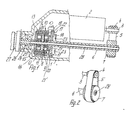
- Fig. 1 denotes a bone drilling machine housing, which is formed by joined housing halves.
- the housing 1 accommodates an electric motor 2, which can be applied to a power source (not shown) by means of electrical switching elements (not shown) or regulated in terms of speed.
- the shaft 3 of the electric motor 2 carries a pinion 4, which is connected via a belt 5 to a gear wheel 7 fixedly arranged on an output shaft 6 mounted in the machine housing 1.
- the output shaft 6 is axially parallel to the shaft 3 and in the embodiment is designed as a hollow shaft.
- the output shaft 6 has teeth 8 which mesh with planet gears 9 of a first planetary gear 10.
- the planet gears 9 are arranged on a freely rotatable carrier disk 11.
- the carrier disk 11 meshes with teeth 12 with further pla Netenradn 13 of a second planetary gear 14, which are supported by a support plate 15.
- Planet gears 9, 13 and carrier disks 11, 15 are encompassed by a common sun gear 16, which meshes with the planet gears 9, 13 of the two planetary gear sets 10 and 14 simultaneously.
- the sun gear 16 is connected via guide pins 17 to a coupling disc 18 which is freely rotatable and freely displaceable on the output shaft.
- the coupling disc 18 is displaceable by an eccentric drive 19 on the output shaft 6 and on the guide pins 17 between two coupling positions and can be coupled by means of cams 20 in one coupling position with a cam disc 21 fixedly arranged on the output shaft 6 and in the other coupling position via cams 22 with machine housings Cam 23 can be brought into engagement.
- a shaft stub is connected to the carrier disk 15, which is supported in the machine housing 1 by ball bearings 25 or the like and is tightly guided by means of a seal 26.
- the shaft end 24 serves as a carrier of a chuck 27 for fixing a drilling tool.
- the output shaft 6 receives a guide tube 28 in the central opening, which extends to the shaft end 24.
- the guide tube 28 enables the reception and implementation of length-oriented materials through the output shaft 6 to the chuck 27 or collet of the clamping cone.
- the electric motor 2 rotates the output shaft 6 via the pinion 4, the belt 5 and the gear wheel 7 operate the eccentric 19 with their cams 20 placed on the cams 21 ⁇ of the cam disk 21, so the cam disk 21 takes the coupling disk 18 along with the revolutions of the output shaft 6 and through this the sun gear 16 is rotated via the guide pins 17.
- the sun gear 16 Through the sun gear 16, the planet gears 9, 13 and the carrier disks 11, 15 and further the stub shaft are carried in a ratio of 1: 1 to the output shaft.
- the coupling disc 18 By moving the coupling disc 18 by means of the eccentric drive 19 until the cams 22 abut against the cams 23 fixed to the housing, the coupling disc 18 is fixed and the sun gear 16 is held non-rotatably via the guide pins. Via the toothing 8, the planet gears 9 and carrier disk 11, the toothing 12, the planet gears 13 and the carrier disk 15, a torque with speed reduction is exerted on the shaft end 24.
- the two planetary gear 10, 14 made of any material, for. B. can be formed from a metallic material or a plastic. Predetermined reductions can be achieved by appropriate dimensioning of the planetary gear.
- the bone drilling machine thus has a first flexible gear stage and a mechanically acting second gear stage, the first gear stage leading to a soft and slip-free start-up without tolerance problems.
- a machine housing fixed roller bearing for the sun gear 16 is designated.
Landscapes
- Health & Medical Sciences (AREA)
- Surgery (AREA)
- Engineering & Computer Science (AREA)
- Life Sciences & Earth Sciences (AREA)
- Heart & Thoracic Surgery (AREA)
- Medical Informatics (AREA)
- Nuclear Medicine, Radiotherapy & Molecular Imaging (AREA)
- Oral & Maxillofacial Surgery (AREA)
- Dentistry (AREA)
- Biomedical Technology (AREA)
- Mechanical Engineering (AREA)
- Orthopedic Medicine & Surgery (AREA)
- Molecular Biology (AREA)
- Animal Behavior & Ethology (AREA)
- General Health & Medical Sciences (AREA)
- Public Health (AREA)
- Veterinary Medicine (AREA)
- Surgical Instruments (AREA)
- Transmission Devices (AREA)
- Retarders (AREA)
Applications Claiming Priority (2)
| Application Number | Priority Date | Filing Date | Title |
|---|---|---|---|
| DE19863639696 DE3639696A1 (de) | 1986-11-20 | 1986-11-20 | Knochenbohrmaschine |
| DE3639696 | 1986-11-20 |
Publications (2)
| Publication Number | Publication Date |
|---|---|
| EP0272434A2 true EP0272434A2 (fr) | 1988-06-29 |
| EP0272434A3 EP0272434A3 (fr) | 1988-07-27 |
Family
ID=6314393
Family Applications (1)
| Application Number | Title | Priority Date | Filing Date |
|---|---|---|---|
| EP87116685A Withdrawn EP0272434A3 (fr) | 1986-11-20 | 1987-11-12 | Perceuse osseuse |
Country Status (2)
| Country | Link |
|---|---|
| EP (1) | EP0272434A3 (fr) |
| DE (2) | DE3639696A1 (fr) |
Cited By (4)
| Publication number | Priority date | Publication date | Assignee | Title |
|---|---|---|---|---|
| US5553675A (en) * | 1994-06-10 | 1996-09-10 | Minnesota Mining And Manufacturing Company | Orthopedic surgical device |
| US8312937B2 (en) | 2001-08-24 | 2012-11-20 | Black & Decker Inc. | Battery for a power tool with a battery pack ejector |
| CN105342666A (zh) * | 2015-12-14 | 2016-02-24 | 黄少安 | 一种电动骨科钻孔装置 |
| CN108113731A (zh) * | 2017-12-29 | 2018-06-05 | 丁春林 | 一种骨科用骨钉埋头钻 |
Families Citing this family (4)
| Publication number | Priority date | Publication date | Assignee | Title |
|---|---|---|---|---|
| DE4117664C1 (en) * | 1991-05-29 | 1993-03-04 | Guenther Boehler Gmbh, 7819 Denzlingen, De | Microsurgical drill for driving tool extension into bone - has clamping insert with tubular shaft, forming integral unit with chuck, pressure pin, and spring |
| US6656626B1 (en) | 1999-06-01 | 2003-12-02 | Porter-Cable Corporation | Cordless power tool battery release mechanism |
| EP2238920B1 (fr) * | 2009-04-09 | 2013-02-20 | Arthrex Inc | Pièce à main médicale, en particulier chirurgicale |
| CN103006290B (zh) * | 2013-01-12 | 2015-01-14 | 青岛理工大学 | 采用阶梯钻头的轴向力可控的外科骨钻 |
Citations (4)
| Publication number | Priority date | Publication date | Assignee | Title |
|---|---|---|---|---|
| US3120845A (en) * | 1961-02-20 | 1964-02-11 | David B Horner | Self-powered surgical drill |
| FR1457220A (fr) * | 1964-12-11 | 1966-10-28 | Metabowerke Kg | Mécanisme d'entraînement en particulier pour outils électriques |
| US3734207A (en) * | 1971-12-27 | 1973-05-22 | M Fishbein | Battery powered orthopedic cutting tool |
| GB2124112A (en) * | 1982-07-16 | 1984-02-15 | Matsushita Electric Works Ltd | A hand held electric tool |
-
1986
- 1986-11-20 DE DE19863639696 patent/DE3639696A1/de not_active Withdrawn
- 1986-11-20 DE DE19868631123 patent/DE8631123U1/de not_active Expired
-
1987
- 1987-11-12 EP EP87116685A patent/EP0272434A3/fr not_active Withdrawn
Patent Citations (4)
| Publication number | Priority date | Publication date | Assignee | Title |
|---|---|---|---|---|
| US3120845A (en) * | 1961-02-20 | 1964-02-11 | David B Horner | Self-powered surgical drill |
| FR1457220A (fr) * | 1964-12-11 | 1966-10-28 | Metabowerke Kg | Mécanisme d'entraînement en particulier pour outils électriques |
| US3734207A (en) * | 1971-12-27 | 1973-05-22 | M Fishbein | Battery powered orthopedic cutting tool |
| GB2124112A (en) * | 1982-07-16 | 1984-02-15 | Matsushita Electric Works Ltd | A hand held electric tool |
Cited By (8)
| Publication number | Priority date | Publication date | Assignee | Title |
|---|---|---|---|---|
| US5553675A (en) * | 1994-06-10 | 1996-09-10 | Minnesota Mining And Manufacturing Company | Orthopedic surgical device |
| US5792573A (en) * | 1994-06-10 | 1998-08-11 | Pitzen; James F. | Rechargeable battery adapted to be attached to orthopedic device |
| USRE40681E1 (en) * | 1994-06-10 | 2009-03-24 | Linvatec Corporation | Combination rechargeable, detachable battery system and power tool |
| USRE40848E1 (en) | 1994-06-10 | 2009-07-14 | Pitzen James F | Combination rechargeable, detachable battery system and power tool |
| US8312937B2 (en) | 2001-08-24 | 2012-11-20 | Black & Decker Inc. | Battery for a power tool with a battery pack ejector |
| CN105342666A (zh) * | 2015-12-14 | 2016-02-24 | 黄少安 | 一种电动骨科钻孔装置 |
| CN108113731A (zh) * | 2017-12-29 | 2018-06-05 | 丁春林 | 一种骨科用骨钉埋头钻 |
| CN108113731B (zh) * | 2017-12-29 | 2020-07-31 | 鹤壁市人民医院 | 一种骨科用骨钉埋头钻 |
Also Published As
| Publication number | Publication date |
|---|---|
| DE3639696A1 (de) | 1988-06-01 |
| EP0272434A3 (fr) | 1988-07-27 |
| DE8631123U1 (de) | 1988-02-18 |
Similar Documents
| Publication | Publication Date | Title |
|---|---|---|
| DE4213291C2 (de) | Getriebeeinrichtung einer handgeführten Bohrhammermaschine | |
| DE4021973C1 (fr) | ||
| DE19611459C2 (de) | Spindelantrieb für eine Werkzeugmaschine | |
| DE19717466B4 (de) | Mehrganggetriebe für Elektrowerkzeugmaschinen | |
| DE3130518C2 (de) | Steuer- und Antriebsvorrichtung, bestehend aus einem Planetengetriebe und einem mit diesem verbundenen Antrieb | |
| DE3423432C2 (de) | Vorrichtung zur Positionierung einer Probe | |
| EP0272434A2 (fr) | Perceuse osseuse | |
| DE4201849C2 (de) | Spindelantriebseinrichtung für Werkzeugmaschinen | |
| EP0040261A1 (fr) | Outil électrique avec engrenage à deux pas | |
| EP0563766A1 (fr) | Broche d'outil, en particulier broche de perçage | |
| DE4209652C1 (en) | Two directional drive for sunroof panel of motor vehicle - has electromotor coupled to drive pinion on drive shaft via reduction gearing | |
| DE19838849C1 (de) | Gangwechselgetriebe für Drehbänke | |
| WO2004047664A1 (fr) | Piece a main medicale ou dentaire pourvue d'un ensemble d'engrenages multietage | |
| EP0581037A2 (fr) | Instrument de traitement médical ou dentaire comportant un outil de traitement entraîné | |
| EP1163976A1 (fr) | Entrainement avec une transmission variable pour un dispositif porte outil | |
| WO2000066318A1 (fr) | Porte-outils et ensemble support d'outils pour supports d'outils entraines en rotation | |
| DE10134928B4 (de) | Verwendung eines Vorschubantriebes | |
| EP1245342B1 (fr) | mécanisme d'avancement | |
| DE102005042718A1 (de) | Werkzeug zur spanenden Bearbeitung von Werkstückoberflächen | |
| DE10316889B4 (de) | Elektrohandwerkzeuggerät mit einem Klemmgesperre | |
| DE10254125B4 (de) | Elektromotorischer Möbelantrieb zum Verstellen von Teilen eines Möbels relativ zueinander | |
| DE960144C (de) | Elektromechanisch gesteuerter Plandrehkopf | |
| DE3538121A1 (de) | Elektrowerkzeug mit einem zweiganggetriebe | |
| EP1127644B1 (fr) | Outil électrique à main | |
| DE3540605A1 (de) | Elektrowerkzeug mit einem zweiganggetriebe |
Legal Events
| Date | Code | Title | Description |
|---|---|---|---|
| PUAI | Public reference made under article 153(3) epc to a published international application that has entered the european phase |
Free format text: ORIGINAL CODE: 0009012 |
|
| PUAL | Search report despatched |
Free format text: ORIGINAL CODE: 0009013 |
|
| AK | Designated contracting states |
Kind code of ref document: A2 Designated state(s): AT BE CH DE ES FR GB GR IT LI LU NL SE |
|
| AK | Designated contracting states |
Kind code of ref document: A3 Designated state(s): AT BE CH DE ES FR GB GR IT LI LU NL SE |
|
| STAA | Information on the status of an ep patent application or granted ep patent |
Free format text: STATUS: THE APPLICATION IS DEEMED TO BE WITHDRAWN |
|
| 18D | Application deemed to be withdrawn |
Effective date: 19890128 |
|
| RIN1 | Information on inventor provided before grant (corrected) |
Inventor name: RICHTER, ULRICH |