EP0272434A2 - Knochenbohrmaschine - Google Patents
Knochenbohrmaschine Download PDFInfo
- Publication number
- EP0272434A2 EP0272434A2 EP87116685A EP87116685A EP0272434A2 EP 0272434 A2 EP0272434 A2 EP 0272434A2 EP 87116685 A EP87116685 A EP 87116685A EP 87116685 A EP87116685 A EP 87116685A EP 0272434 A2 EP0272434 A2 EP 0272434A2
- Authority
- EP
- European Patent Office
- Prior art keywords
- output shaft
- shaft
- drilling machine
- machine according
- bone drilling
- Prior art date
- Legal status (The legal status is an assumption and is not a legal conclusion. Google has not performed a legal analysis and makes no representation as to the accuracy of the status listed.)
- Withdrawn
Links
Images
Classifications
-
- B—PERFORMING OPERATIONS; TRANSPORTING
- B23—MACHINE TOOLS; METAL-WORKING NOT OTHERWISE PROVIDED FOR
- B23Q—DETAILS, COMPONENTS, OR ACCESSORIES FOR MACHINE TOOLS, e.g. ARRANGEMENTS FOR COPYING OR CONTROLLING; MACHINE TOOLS IN GENERAL CHARACTERISED BY THE CONSTRUCTION OF PARTICULAR DETAILS OR COMPONENTS; COMBINATIONS OR ASSOCIATIONS OF METAL-WORKING MACHINES, NOT DIRECTED TO A PARTICULAR RESULT
- B23Q5/00—Driving or feeding mechanisms; Control arrangements therefor
- B23Q5/02—Driving main working members
- B23Q5/04—Driving main working members rotary shafts, e.g. working-spindles
- B23Q5/12—Mechanical drives with means for varying the speed ratio
- B23Q5/14—Mechanical drives with means for varying the speed ratio step-by-step
- B23Q5/142—Mechanical drives with means for varying the speed ratio step-by-step mechanically-operated
-
- A—HUMAN NECESSITIES
- A61—MEDICAL OR VETERINARY SCIENCE; HYGIENE
- A61B—DIAGNOSIS; SURGERY; IDENTIFICATION
- A61B17/00—Surgical instruments, devices or methods, e.g. tourniquets
- A61B17/16—Bone cutting, breaking or removal means other than saws, e.g. Osteoclasts; Drills or chisels for bones; Trepans
- A61B17/1613—Component parts
- A61B17/1622—Drill handpieces
- A61B17/1624—Drive mechanisms therefor
Definitions
- the invention relates to a bone drilling machine with an output shaft which can be rotated in the drilling machine housing by an electric motor and which drives a clamping element for a drilling tool.
- this object is achieved in that the motor shaft is connected to the output shaft by a flexible force transmission member and in that the drive shaft via at least one switchable planetary gearbox rotates a shaft end receiving the tensioning element.
- two planetary gear units are arranged one behind the other between the output shaft and the stub shaft, which have a common sun gear and two axially spaced two independent rotatable carrier disks for the planet gears of the two planetary gear units and the planet gears of the first planetary gear unit with teeth formed on the output shaft and the like
- Planet gears of the second planetary gear are in engagement with a toothing formed on the carrier disk for the planet gears of the first planetary gear, while the carrier disk of the planet gears of the second planetary gear is rotatably connected to the stub shaft.
- the flexible power transmission link, z. B. a toothed belt, to a first gear stage that is free of play and contributes to a soft start of the tensioning element.
- tolerance problems with regard to the distance between the motor shaft and the output shaft or the axis positions have been eliminated and a gear stage with low running noise has been created.
- As a flexible power transmission member, for. B. find a belt drive application, which is expediently guided via pinions of the motor shaft and drive shaft with profiled peripheral surfaces. Can too the power transmission member itself wear profiles on the pinion side. It is understood that electrical speed controls for the drive motor can be maintained, which can now be superimposed by changes in speed by means of switching the planetary gear.
- the sun gear is connected to the output shaft in a non-positive, positive or frictional manner by means of a switchable coupling disc.
- the coupling disc is expediently axially displaceable and freely rotatable between the two positions on the output shaft and non-rotatably mounted on guide pins connected to the sun gear, and the coupling disc can be placed in one position on a cam disc connected to the output shaft and in the other Position can be fixed to cams fixed to the housing. Switching over therefore only requires a simple displacement movement of the coupling disc.
- These axial displacement movements can, for. B. by means of an eccentric drive, which is preferably manually rotatable by an actuator protruding from the drill housing.
- the actuation of the coupling plate for switching can also be done otherwise, e.g. B. done via a lever gear.
- the output shaft and the stub shaft are designed as hollow shafts and a guide tube connected to the stub shaft is arranged in the output shaft.
- the output shaft receives a relatively large bending moment and the through is through the central opening of the guide tube Conduction of length-oriented material, such as drilling wires, optical fibers for endoscopes, without interference and gently possible.
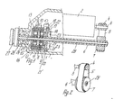
- Fig. 1 denotes a bone drilling machine housing, which is formed by joined housing halves.
- the housing 1 accommodates an electric motor 2, which can be applied to a power source (not shown) by means of electrical switching elements (not shown) or regulated in terms of speed.
- the shaft 3 of the electric motor 2 carries a pinion 4, which is connected via a belt 5 to a gear wheel 7 fixedly arranged on an output shaft 6 mounted in the machine housing 1.
- the output shaft 6 is axially parallel to the shaft 3 and in the embodiment is designed as a hollow shaft.
- the output shaft 6 has teeth 8 which mesh with planet gears 9 of a first planetary gear 10.
- the planet gears 9 are arranged on a freely rotatable carrier disk 11.
- the carrier disk 11 meshes with teeth 12 with further pla Netenradn 13 of a second planetary gear 14, which are supported by a support plate 15.
- Planet gears 9, 13 and carrier disks 11, 15 are encompassed by a common sun gear 16, which meshes with the planet gears 9, 13 of the two planetary gear sets 10 and 14 simultaneously.
- the sun gear 16 is connected via guide pins 17 to a coupling disc 18 which is freely rotatable and freely displaceable on the output shaft.
- the coupling disc 18 is displaceable by an eccentric drive 19 on the output shaft 6 and on the guide pins 17 between two coupling positions and can be coupled by means of cams 20 in one coupling position with a cam disc 21 fixedly arranged on the output shaft 6 and in the other coupling position via cams 22 with machine housings Cam 23 can be brought into engagement.
- a shaft stub is connected to the carrier disk 15, which is supported in the machine housing 1 by ball bearings 25 or the like and is tightly guided by means of a seal 26.
- the shaft end 24 serves as a carrier of a chuck 27 for fixing a drilling tool.
- the output shaft 6 receives a guide tube 28 in the central opening, which extends to the shaft end 24.
- the guide tube 28 enables the reception and implementation of length-oriented materials through the output shaft 6 to the chuck 27 or collet of the clamping cone.
- the electric motor 2 rotates the output shaft 6 via the pinion 4, the belt 5 and the gear wheel 7 operate the eccentric 19 with their cams 20 placed on the cams 21 ⁇ of the cam disk 21, so the cam disk 21 takes the coupling disk 18 along with the revolutions of the output shaft 6 and through this the sun gear 16 is rotated via the guide pins 17.
- the sun gear 16 Through the sun gear 16, the planet gears 9, 13 and the carrier disks 11, 15 and further the stub shaft are carried in a ratio of 1: 1 to the output shaft.
- the coupling disc 18 By moving the coupling disc 18 by means of the eccentric drive 19 until the cams 22 abut against the cams 23 fixed to the housing, the coupling disc 18 is fixed and the sun gear 16 is held non-rotatably via the guide pins. Via the toothing 8, the planet gears 9 and carrier disk 11, the toothing 12, the planet gears 13 and the carrier disk 15, a torque with speed reduction is exerted on the shaft end 24.
- the two planetary gear 10, 14 made of any material, for. B. can be formed from a metallic material or a plastic. Predetermined reductions can be achieved by appropriate dimensioning of the planetary gear.
- the bone drilling machine thus has a first flexible gear stage and a mechanically acting second gear stage, the first gear stage leading to a soft and slip-free start-up without tolerance problems.
- a machine housing fixed roller bearing for the sun gear 16 is designated.
Landscapes
- Health & Medical Sciences (AREA)
- Engineering & Computer Science (AREA)
- Life Sciences & Earth Sciences (AREA)
- Surgery (AREA)
- Oral & Maxillofacial Surgery (AREA)
- Medical Informatics (AREA)
- Nuclear Medicine, Radiotherapy & Molecular Imaging (AREA)
- Dentistry (AREA)
- Mechanical Engineering (AREA)
- Biomedical Technology (AREA)
- Heart & Thoracic Surgery (AREA)
- Orthopedic Medicine & Surgery (AREA)
- Molecular Biology (AREA)
- Animal Behavior & Ethology (AREA)
- General Health & Medical Sciences (AREA)
- Public Health (AREA)
- Veterinary Medicine (AREA)
- Surgical Instruments (AREA)
- Transmission Devices (AREA)
Abstract
Description
- Die Erfindung betrifft eine Knochenbohrmaschine mit einer im Bohrmaschinengehäuse durch einen Elektromotor drehbaren Abtriebswelle, die ein Spannelement für ein Bohrwerkzeug antreibt.
- Bei einer bekannten chirurgischen Handbohrmaschine (DE-OS 3 317 398) steht der Antriebsmotor über ein Kegelräderpaar permanent mit einer ein Spannfutter aufweisenden Abtriebswelle in Verbindung. Drehzahländerungen der Abtriebswelle erfolgen bei dieser Knochenbohrmaschine durch Veränderung des Widerstandswertes eines den Stromkreis des Antriebsmotors beeinflußenden Potentiometers. Diese über den gesamten Drehzahlbereich sich erstreckende Regelung der Motordrehzahl führt jedoch zu ungünstigen Drehmomentbeeinflussungen. Weiter können sich stoßartige Drehmomentänderungen über die Kegelräder direkt auf die Abtriebswelle und das Spannfutter übertragen, was die auf chirurgischem Gebiet empfindlichen Bohrvorgänge negativ belastet.
- Es ist Aufgabe der Erfindung, bei Knochenbohrmaschinen die Abtriebswelle stoßfrei und umschaltbar auszubilden und beliebig Bohrwerkzeuge und längenorientiertes Material zu fassen.
- Der Erfindung gemäß ist diese Aufgabe dadurch gelöst, daß die Motorwelle durch ein flexibles Kraftübertragungsglied mit der Abtriebswelle in Verbindung steht und daß die Ab triebswelle über mindestens ein umschaltbares Planetenradgetriebe einen das Spannelement aufnehmenden Wellenstumpf dreht. Nach bevorzugter Ausführung sind zwischen der Abtriebswelle und dem Wellenstumpf zwei Planetenradgetriebe hintereinander angeordnet, die ein gemeinsames Sonnenrad und im axialen Abstand voneinander zwei unabhängige drehbewegliche Trägerscheiben für die Planetenräder der beiden Planetenradgetriebe aufweisen und die Planetenräder des ersten Planetenradgetriebes mit einer auf der Abtriebswelle ausgebildeten Zahnung und die Planetenräder des zweiten Planetenradgetriebes mit einer an der Trägerscheibe für die Planetenräder des ersten Planetenradgetriebes ausgebildeten Zahnung in Eingriff stehen, während die Trägerscheibe der Planetenräder des zweiten Planetenradgetriebes mit dem Wellenstumpf drehfest verbunden ist. Auf diese Weise ist erreicht, daß störende Stoßbelastungen zwischen Antriebsmotor und Abtriebswelle vermieden sind und durch die mechanischen Umschaltungen Drehzahländerungen unter Beibehaltung der Motordrehzahl und des Drehmoments vornehmbar sind.
- Dabei führt das flexible Kraftübertragungsglied, z. B. ein Zahnriemen, zu einer ersten Getriebestufe, die spielfrei ist und zu einem weichen Anlaufen des Spannelements beiträgt. Außerdem sind Toleranzprobleme hinsichtlich des Abstandes von Motorwelle und Abtriebswelle bzw. der Achsenlagen beseitigt und eine Getriebestufe mit geringen Laufgeräuschen geschaffen. Als flexibles Kraftübertragungsglied kann z. B. ein Riementrieb Anwendung finden, der zweckmäßig über Ritzel der Motorwelle und Antriebswelle mit profilierten Umfangsflächen geführt ist. Auch kann das Kraftübertragungsglied selbst ritzelseitig Profilierungen tragen. Es versteht sich, daß elektrische Drehzahlregelungen für den Antriebsmotor beibehaltbar sind, die nunmehr durch Drehzahlveränderungen vermittels Umschaltungen der Planetenradgetriebe überlagerbar sind.
- In Ausgestaltung der Bohrmaschine ist vorgesehen, das Sonnenrad durch eine schaltbare Kuppelscheibe mit der Abtriebswelle kraft-, form- oder reibschlüssig zu verbinden. Zweckmäßig ist die Kuppelscheibe zwischen zwei Stellungen axial frei verschieblich und frei drehbar auf der Abtriebswelle angeordnet und auf mit dem Sonnenrad fest verbundenen Führungsstiften gegenüber dem Sonnenrad unverdrehbar gelagert und die Kuppelscheibe in der einen Stellung an einer mit der Abtriebswelle drehfest verbundenen Nockenscheibe anlegbar und in der anderen Stellung an gehäusefeste Nocken fixierbar. Zu Umschaltungen bedarf es somit lediglich einer einfachen Verschiebebewegung der Kuppelscheibe. Diese axialen Verschiebebewegungen lassen sich, z. B. mittels eines Exzentertriebes erreichen, der bevorzugt durch ein aus dem Bohrmaschinengehäuse herausragendes Betätigungsglied manuell drehbar ist. Die Betätigung der Kuppelscheibe zu Umschaltungen kann auch anderweitig, z. B. über ein Hebelgetriebe erfolgen.
- In Ausbildung der Knochenbohrmaschine ist vorgesehen, die Abtriebswelle und den Wellenstumpf als Hohlwellen auszubilden und in der Abtriebswelle ein mit dem Wellenstumpf verbundenes Führungsrohr anzuordnen. Auf diese Weise erhält die Abtriebswelle ein relativ großes Biegemoment und über die Mittelöffnung des Führungsrohres ist die Durch leitung von längenorientiertem Material, wie Bohrdrähten, Lichtleitfasern für Endoskope störungsfrei und schonend möglich.
- Es entspricht der Erfindung, die Bohrdrähte entweder manuell vorzuschieben oder maschinell, insbesondere von der Drehrichtung abhängig selbsttätig vorzuschieben oder zurückzuholen. Selbsttätige Verschiebungen der Bohrdrähte sind durch ein motorisch drehbares Klemmrollengesperre bewirkbar.
- Die Erfindung ist anhand eines Ausführungsbeispiels in der Zeichnung verdeutlicht. Es zeigen:
- Fig. 1 einen Teilschnitt einer Knochenbohrmaschine und
- Fig. 2 eine erste Getriebestufe, perspektivisch.
- In Fig. 1 ist mit 1 ein Knochenbohrmaschinengehäuse bezeichnet, das durch zusammengefügte Gehäusehälften gebildet ist. Das Gehäuse 1 nimmt einen Elektromotor 2 auf, der durch elektrische Schaltelemente (nicht gezeigt) an eine Stromquelle (nicht gezeigt) anlegbar bzw. in Drehzahlen regelbar ist. Die Welle 3 des Elektromotors 2 trägt ein Ritzel 4, das über einen Riemen 5 mit einem auf einer im Maschinengehäuse 1 gelagerten Abtriebswelle 6 fest angeordneten Getrieberad 7 in Verbindung steht. Die Abtriebswelle 6 ist achsparallel zur Welle 3 ausgebildet und beim Ausführungsbeispiel als Hohlwelle ausgeführt. An ihrem dem Getrieberad 7 abgewandten Ende trägt die Abtriebswelle 6 eine Zahnung 8, die mit Planetenrädern 9 eines ersten Planetenradgetriebes 10 kämmen. Die Planetenräder 9 sind an einer frei drehbaren Trägerscheibe 11 angeordnet. Die Trägerscheibe 11 kämmt mit einer Zahnung 12 mit weiteren Pla netenrädern 13 eines zweiten Planetenradgetriebes 14, die durch eine Trägerscheibe 15 getragen sind. Planetenräder 9, 13 und Trägerscheiben 11, 15 sind durch ein gemeinsames Sonnenrad 16 umfaßt, das mit den Planetenrädern 9, 13 der beiden Planetenradgetriebe 10 und 14 gleichzeitig in Eingriff steht. Das Sonnenrad 16 steht über Führungsstifte 17 mit einer Kuppelscheibe 18 in Verbindung, die zur Abtriebswelle frei drehbar und auf dieser frei verschiebbar ist. Die Kuppelscheibe 18 ist durch einen Exzentertrieb 19 auf der Abtriebswelle 6 und auf den Führungsstiften 17 zwischen zwei Kuppelstellungen verschieblich und vermittels Nocken 20 in der einen Kuppelstellung mit einer auf der Abtriebswelle 6 fest angeordneten Nockenscheibe 21 kuppelbar und in der anderen Kuppelstellung über Nocken 22 mit maschinengehäusefesten Nocken 23 in Eingriff bringbar.
- Mit der Trägerscheibe 15 steht ein Wellenstumpf in Verbindung, der im Maschinengehäuse 1 durch Kugellager 25 od. dgl. gestützt und vermittels einer Dichtung 26 dicht geführt ist. Der Wellenstumpf 24 dient als Träger eines Spannfutters 27 für die Fixierung eines Bohrwerkzeugs. Die Abtriebswelle 6 nimmt in der Mittelöffnung ein Führungsrohr 28 auf, das sich bis zum Wellenstumpf 24 erstreckt. Das Führungsrohr 28 ermöglicht die Aufnahme und Durchführung von längenorientierten Materialien durch die Abtriebswelle 6 zum Spannfutter 27 bzw. Spannzange der Spannkonus.
- In der in Fig. 1 gezeigten Stellung dreht der Elektromotor 2 über das Ritzel 4, den Riemen 5 und das Getrieberad 7 die Abtriebswelle 6. Ist die Kuppelscheibe 18 durch Be tätigen des Exzentertriebs19 mit ihren Nocken 20 an die Nocken 21ʹ der Nockenscheibe 21 angelegt, so nimmt bei den Umläufen der Abtriebswelle 6 die Nockenscheibe 21 die Kuppelscheibe 18 mit und durch diese wird über die Führungsstifte 17 das Sonnenrad 16 gedreht. Durch das Sonnenrad 16 werden die Planetenräder 9, 13 und die Trägerscheiben 11, 15 und weiter der Wellenstumpf im Verhältnis 1:1 zur Abtriebswelle mitgenommen.
- Durch Verschieben der Kuppelscheibe 18 mittels des Exzentertriebs 19 bis zur Anlage der Nocken 22 an die gehäusefesten Nocken 23 ist die Kuppelscheibe 18 fixiert und über die Führungsstifte das Sonnenrad 16 unverdrehbar gehalten. Über die Zahnung 8, die Planetenräder 9 und Trägerscheibe 11, der Zahnung 12, den Planetenrädern 13 und der Trägerscheibe 15 wird auf den Wellenstumpf 24 ein Drehmoment mit Drehzahluntersetzung ausgeübt. Es versteht sich, daß die beiden Planetenradgetriebe 10, 14 aus einem beliebigen Werkstoff, z. B. einem metallischen Werkstoff oder einem Kunststoff gebildet sein können. Durch entsprechende Bemessung der Planetenradgetriebe sind vorbestimmte Untersetzungen erzielbar.
- Die Knochenbohrmaschine weist somit eine erste flexible Getriebestufe und eine mechanisch wirkende zweite Getriebestufe auf, wobei die erste Getriebestufe zu einem weichen und schlupffreien Anlaufen ohne Toleranzprobleme führt. Mit 29 ist ein maschinengehäusefestes Rollenlager für das Sonnenrad 16 bezeichnet.
Claims (9)
Applications Claiming Priority (2)
| Application Number | Priority Date | Filing Date | Title |
|---|---|---|---|
| DE3639696 | 1986-11-20 | ||
| DE19863639696 DE3639696A1 (de) | 1986-11-20 | 1986-11-20 | Knochenbohrmaschine |
Publications (2)
| Publication Number | Publication Date |
|---|---|
| EP0272434A2 true EP0272434A2 (de) | 1988-06-29 |
| EP0272434A3 EP0272434A3 (de) | 1988-07-27 |
Family
ID=6314393
Family Applications (1)
| Application Number | Title | Priority Date | Filing Date |
|---|---|---|---|
| EP87116685A Withdrawn EP0272434A3 (de) | 1986-11-20 | 1987-11-12 | Knochenbohrmaschine |
Country Status (2)
| Country | Link |
|---|---|
| EP (1) | EP0272434A3 (de) |
| DE (2) | DE8631123U1 (de) |
Cited By (4)
| Publication number | Priority date | Publication date | Assignee | Title |
|---|---|---|---|---|
| US5553675A (en) * | 1994-06-10 | 1996-09-10 | Minnesota Mining And Manufacturing Company | Orthopedic surgical device |
| US8312937B2 (en) | 2001-08-24 | 2012-11-20 | Black & Decker Inc. | Battery for a power tool with a battery pack ejector |
| CN105342666A (zh) * | 2015-12-14 | 2016-02-24 | 黄少安 | 一种电动骨科钻孔装置 |
| CN108113731A (zh) * | 2017-12-29 | 2018-06-05 | 丁春林 | 一种骨科用骨钉埋头钻 |
Families Citing this family (4)
| Publication number | Priority date | Publication date | Assignee | Title |
|---|---|---|---|---|
| DE4117664C1 (en) * | 1991-05-29 | 1993-03-04 | Guenther Boehler Gmbh, 7819 Denzlingen, De | Microsurgical drill for driving tool extension into bone - has clamping insert with tubular shaft, forming integral unit with chuck, pressure pin, and spring |
| US6656626B1 (en) | 1999-06-01 | 2003-12-02 | Porter-Cable Corporation | Cordless power tool battery release mechanism |
| EP2238920B1 (de) | 2009-04-09 | 2013-02-20 | Arthrex Inc | Medizinisches, insbesondere chirurgisches, Handstück |
| CN103006290B (zh) * | 2013-01-12 | 2015-01-14 | 青岛理工大学 | 采用阶梯钻头的轴向力可控的外科骨钻 |
Citations (4)
| Publication number | Priority date | Publication date | Assignee | Title |
|---|---|---|---|---|
| US3120845A (en) * | 1961-02-20 | 1964-02-11 | David B Horner | Self-powered surgical drill |
| FR1457220A (fr) * | 1964-12-11 | 1966-10-28 | Metabowerke Kg | Mécanisme d'entraînement en particulier pour outils électriques |
| US3734207A (en) * | 1971-12-27 | 1973-05-22 | M Fishbein | Battery powered orthopedic cutting tool |
| GB2124112A (en) * | 1982-07-16 | 1984-02-15 | Matsushita Electric Works Ltd | A hand held electric tool |
-
1986
- 1986-11-20 DE DE19868631123 patent/DE8631123U1/de not_active Expired
- 1986-11-20 DE DE19863639696 patent/DE3639696A1/de not_active Withdrawn
-
1987
- 1987-11-12 EP EP87116685A patent/EP0272434A3/de not_active Withdrawn
Patent Citations (4)
| Publication number | Priority date | Publication date | Assignee | Title |
|---|---|---|---|---|
| US3120845A (en) * | 1961-02-20 | 1964-02-11 | David B Horner | Self-powered surgical drill |
| FR1457220A (fr) * | 1964-12-11 | 1966-10-28 | Metabowerke Kg | Mécanisme d'entraînement en particulier pour outils électriques |
| US3734207A (en) * | 1971-12-27 | 1973-05-22 | M Fishbein | Battery powered orthopedic cutting tool |
| GB2124112A (en) * | 1982-07-16 | 1984-02-15 | Matsushita Electric Works Ltd | A hand held electric tool |
Cited By (8)
| Publication number | Priority date | Publication date | Assignee | Title |
|---|---|---|---|---|
| US5553675A (en) * | 1994-06-10 | 1996-09-10 | Minnesota Mining And Manufacturing Company | Orthopedic surgical device |
| US5792573A (en) * | 1994-06-10 | 1998-08-11 | Pitzen; James F. | Rechargeable battery adapted to be attached to orthopedic device |
| USRE40681E1 (en) * | 1994-06-10 | 2009-03-24 | Linvatec Corporation | Combination rechargeable, detachable battery system and power tool |
| USRE40848E1 (en) | 1994-06-10 | 2009-07-14 | Pitzen James F | Combination rechargeable, detachable battery system and power tool |
| US8312937B2 (en) | 2001-08-24 | 2012-11-20 | Black & Decker Inc. | Battery for a power tool with a battery pack ejector |
| CN105342666A (zh) * | 2015-12-14 | 2016-02-24 | 黄少安 | 一种电动骨科钻孔装置 |
| CN108113731A (zh) * | 2017-12-29 | 2018-06-05 | 丁春林 | 一种骨科用骨钉埋头钻 |
| CN108113731B (zh) * | 2017-12-29 | 2020-07-31 | 鹤壁市人民医院 | 一种骨科用骨钉埋头钻 |
Also Published As
| Publication number | Publication date |
|---|---|
| EP0272434A3 (de) | 1988-07-27 |
| DE3639696A1 (de) | 1988-06-01 |
| DE8631123U1 (de) | 1988-02-18 |
Similar Documents
| Publication | Publication Date | Title |
|---|---|---|
| DE4213291C2 (de) | Getriebeeinrichtung einer handgeführten Bohrhammermaschine | |
| DE4021973C1 (de) | ||
| DE19611459C2 (de) | Spindelantrieb für eine Werkzeugmaschine | |
| DE19717466B4 (de) | Mehrganggetriebe für Elektrowerkzeugmaschinen | |
| DE3130518C2 (de) | Steuer- und Antriebsvorrichtung, bestehend aus einem Planetengetriebe und einem mit diesem verbundenen Antrieb | |
| DE3423432C2 (de) | Vorrichtung zur Positionierung einer Probe | |
| EP0272434A2 (de) | Knochenbohrmaschine | |
| DE4201849C2 (de) | Spindelantriebseinrichtung für Werkzeugmaschinen | |
| EP0040261A1 (de) | Elektrowerkzeug mit einem Zweiganggetriebe | |
| EP0563766A1 (de) | Werkzeugspindel, insbesondere Bohrspindel | |
| DE19838849C1 (de) | Gangwechselgetriebe für Drehbänke | |
| DE4209652C1 (en) | Two directional drive for sunroof panel of motor vehicle - has electromotor coupled to drive pinion on drive shaft via reduction gearing | |
| WO2004047664A1 (de) | Ärztliches oder zahnärztliches handstück mit mehrstufiger getriebeanordnung | |
| EP0581037A2 (de) | Ärztliches oder zahnärztliches Behandlungsinstrument mit einem angetriebenen Behandlungswerkzeug | |
| EP1163976A1 (de) | Drehantrieb mit einer Drehzahlumschalteinrichtung für eine Werkzeughaltevorrichtung | |
| WO2000066318A1 (de) | Werkzeugträger und werkzeuganordnung für werkzeughalter von rotierend angetriebenen werkzeugen | |
| DE10134928B4 (de) | Verwendung eines Vorschubantriebes | |
| EP1245342B1 (de) | Vorschubantrieb | |
| DE102005042718A1 (de) | Werkzeug zur spanenden Bearbeitung von Werkstückoberflächen | |
| DE10316889B4 (de) | Elektrohandwerkzeuggerät mit einem Klemmgesperre | |
| DE10254125B4 (de) | Elektromotorischer Möbelantrieb zum Verstellen von Teilen eines Möbels relativ zueinander | |
| DE960144C (de) | Elektromechanisch gesteuerter Plandrehkopf | |
| DE3538121A1 (de) | Elektrowerkzeug mit einem zweiganggetriebe | |
| EP1127644B1 (de) | Elektrohandwerkzeug | |
| DE3540605A1 (de) | Elektrowerkzeug mit einem zweiganggetriebe |
Legal Events
| Date | Code | Title | Description |
|---|---|---|---|
| PUAI | Public reference made under article 153(3) epc to a published international application that has entered the european phase |
Free format text: ORIGINAL CODE: 0009012 |
|
| PUAL | Search report despatched |
Free format text: ORIGINAL CODE: 0009013 |
|
| AK | Designated contracting states |
Kind code of ref document: A2 Designated state(s): AT BE CH DE ES FR GB GR IT LI LU NL SE |
|
| AK | Designated contracting states |
Kind code of ref document: A3 Designated state(s): AT BE CH DE ES FR GB GR IT LI LU NL SE |
|
| STAA | Information on the status of an ep patent application or granted ep patent |
Free format text: STATUS: THE APPLICATION IS DEEMED TO BE WITHDRAWN |
|
| 18D | Application deemed to be withdrawn |
Effective date: 19890128 |
|
| RIN1 | Information on inventor provided before grant (corrected) |
Inventor name: RICHTER, ULRICH |