EP1243803B1 - Verbindungsstelle zwischen zwei Werkzeugteilen - Google Patents
Verbindungsstelle zwischen zwei Werkzeugteilen Download PDFInfo
- Publication number
- EP1243803B1 EP1243803B1 EP02004826A EP02004826A EP1243803B1 EP 1243803 B1 EP1243803 B1 EP 1243803B1 EP 02004826 A EP02004826 A EP 02004826A EP 02004826 A EP02004826 A EP 02004826A EP 1243803 B1 EP1243803 B1 EP 1243803B1
- Authority
- EP
- European Patent Office
- Prior art keywords
- tool
- tool part
- region
- resilient element
- elastic element
- Prior art date
- Legal status (The legal status is an assumption and is not a legal conclusion. Google has not performed a legal analysis and makes no representation as to the accuracy of the status listed.)
- Expired - Lifetime
Links
- 230000000149 penetrating effect Effects 0.000 claims 1
- 230000002441 reversible effect Effects 0.000 abstract 1
- 238000003754 machining Methods 0.000 description 2
- 238000004873 anchoring Methods 0.000 description 1
- 238000004519 manufacturing process Methods 0.000 description 1
- 239000000463 material Substances 0.000 description 1
- 239000002184 metal Substances 0.000 description 1
- 230000002093 peripheral effect Effects 0.000 description 1
- 125000006850 spacer group Chemical group 0.000 description 1
Images

Classifications
-
- B—PERFORMING OPERATIONS; TRANSPORTING
- B23—MACHINE TOOLS; METAL-WORKING NOT OTHERWISE PROVIDED FOR
- B23B—TURNING; BORING
- B23B31/00—Chucks; Expansion mandrels; Adaptations thereof for remote control
- B23B31/02—Chucks
- B23B31/026—Chucks the radial or angular position of the tool being adjustable
-
- Y—GENERAL TAGGING OF NEW TECHNOLOGICAL DEVELOPMENTS; GENERAL TAGGING OF CROSS-SECTIONAL TECHNOLOGIES SPANNING OVER SEVERAL SECTIONS OF THE IPC; TECHNICAL SUBJECTS COVERED BY FORMER USPC CROSS-REFERENCE ART COLLECTIONS [XRACs] AND DIGESTS
- Y10—TECHNICAL SUBJECTS COVERED BY FORMER USPC
- Y10T—TECHNICAL SUBJECTS COVERED BY FORMER US CLASSIFICATION
- Y10T279/00—Chucks or sockets
- Y10T279/17—Socket type
- Y10T279/17666—Radially reciprocating jaws
- Y10T279/17675—Transverse-screw actuated
-
- Y—GENERAL TAGGING OF NEW TECHNOLOGICAL DEVELOPMENTS; GENERAL TAGGING OF CROSS-SECTIONAL TECHNOLOGIES SPANNING OVER SEVERAL SECTIONS OF THE IPC; TECHNICAL SUBJECTS COVERED BY FORMER USPC CROSS-REFERENCE ART COLLECTIONS [XRACs] AND DIGESTS
- Y10—TECHNICAL SUBJECTS COVERED BY FORMER USPC
- Y10T—TECHNICAL SUBJECTS COVERED BY FORMER US CLASSIFICATION
- Y10T403/00—Joints and connections
- Y10T403/16—Joints and connections with adjunctive protector, broken parts retainer, repair, assembly or disassembly feature
- Y10T403/1616—Position or guide means
-
- Y—GENERAL TAGGING OF NEW TECHNOLOGICAL DEVELOPMENTS; GENERAL TAGGING OF CROSS-SECTIONAL TECHNOLOGIES SPANNING OVER SEVERAL SECTIONS OF THE IPC; TECHNICAL SUBJECTS COVERED BY FORMER USPC CROSS-REFERENCE ART COLLECTIONS [XRACs] AND DIGESTS
- Y10—TECHNICAL SUBJECTS COVERED BY FORMER USPC
- Y10T—TECHNICAL SUBJECTS COVERED BY FORMER US CLASSIFICATION
- Y10T403/00—Joints and connections
- Y10T403/40—Radially spaced members joined by independent coupling
- Y10T403/405—Flexible intermediate member
-
- Y—GENERAL TAGGING OF NEW TECHNOLOGICAL DEVELOPMENTS; GENERAL TAGGING OF CROSS-SECTIONAL TECHNOLOGIES SPANNING OVER SEVERAL SECTIONS OF THE IPC; TECHNICAL SUBJECTS COVERED BY FORMER USPC CROSS-REFERENCE ART COLLECTIONS [XRACs] AND DIGESTS
- Y10—TECHNICAL SUBJECTS COVERED BY FORMER USPC
- Y10T—TECHNICAL SUBJECTS COVERED BY FORMER US CLASSIFICATION
- Y10T403/00—Joints and connections
- Y10T403/70—Interfitted members
- Y10T403/7018—Interfitted members including separably interposed key
- Y10T403/7021—Axially extending
- Y10T403/7022—Resilient
-
- Y—GENERAL TAGGING OF NEW TECHNOLOGICAL DEVELOPMENTS; GENERAL TAGGING OF CROSS-SECTIONAL TECHNOLOGIES SPANNING OVER SEVERAL SECTIONS OF THE IPC; TECHNICAL SUBJECTS COVERED BY FORMER USPC CROSS-REFERENCE ART COLLECTIONS [XRACs] AND DIGESTS
- Y10—TECHNICAL SUBJECTS COVERED BY FORMER USPC
- Y10T—TECHNICAL SUBJECTS COVERED BY FORMER US CLASSIFICATION
- Y10T408/00—Cutting by use of rotating axially moving tool
- Y10T408/94—Tool-support
- Y10T408/95—Tool-support with tool-retaining means
-
- Y—GENERAL TAGGING OF NEW TECHNOLOGICAL DEVELOPMENTS; GENERAL TAGGING OF CROSS-SECTIONAL TECHNOLOGIES SPANNING OVER SEVERAL SECTIONS OF THE IPC; TECHNICAL SUBJECTS COVERED BY FORMER USPC CROSS-REFERENCE ART COLLECTIONS [XRACs] AND DIGESTS
- Y10—TECHNICAL SUBJECTS COVERED BY FORMER USPC
- Y10T—TECHNICAL SUBJECTS COVERED BY FORMER US CLASSIFICATION
- Y10T409/00—Gear cutting, milling, or planing
- Y10T409/30—Milling
- Y10T409/309352—Cutter spindle or spindle support
- Y10T409/309408—Cutter spindle or spindle support with cutter holder
- Y10T409/309464—Cutter spindle or spindle support with cutter holder and draw bar
-
- Y—GENERAL TAGGING OF NEW TECHNOLOGICAL DEVELOPMENTS; GENERAL TAGGING OF CROSS-SECTIONAL TECHNOLOGIES SPANNING OVER SEVERAL SECTIONS OF THE IPC; TECHNICAL SUBJECTS COVERED BY FORMER USPC CROSS-REFERENCE ART COLLECTIONS [XRACs] AND DIGESTS
- Y10—TECHNICAL SUBJECTS COVERED BY FORMER USPC
- Y10T—TECHNICAL SUBJECTS COVERED BY FORMER US CLASSIFICATION
- Y10T409/00—Gear cutting, milling, or planing
- Y10T409/30—Milling
- Y10T409/30952—Milling with cutter holder
-
- Y—GENERAL TAGGING OF NEW TECHNOLOGICAL DEVELOPMENTS; GENERAL TAGGING OF CROSS-SECTIONAL TECHNOLOGIES SPANNING OVER SEVERAL SECTIONS OF THE IPC; TECHNICAL SUBJECTS COVERED BY FORMER USPC CROSS-REFERENCE ART COLLECTIONS [XRACs] AND DIGESTS
- Y10—TECHNICAL SUBJECTS COVERED BY FORMER USPC
- Y10T—TECHNICAL SUBJECTS COVERED BY FORMER US CLASSIFICATION
- Y10T82/00—Turning
- Y10T82/25—Lathe
- Y10T82/2585—Tool rest
- Y10T82/2589—Quick release tool or holder clamp
-
- Y—GENERAL TAGGING OF NEW TECHNOLOGICAL DEVELOPMENTS; GENERAL TAGGING OF CROSS-SECTIONAL TECHNOLOGIES SPANNING OVER SEVERAL SECTIONS OF THE IPC; TECHNICAL SUBJECTS COVERED BY FORMER USPC CROSS-REFERENCE ART COLLECTIONS [XRACs] AND DIGESTS
- Y10—TECHNICAL SUBJECTS COVERED BY FORMER USPC
- Y10T—TECHNICAL SUBJECTS COVERED BY FORMER US CLASSIFICATION
- Y10T82/00—Turning
- Y10T82/25—Lathe
- Y10T82/2585—Tool rest
- Y10T82/2591—Tool post
Definitions
- the invention relates to a tool having a connection point between two tool parts according to the preamble of claim 1 (see, for example, US Pat. EP-0 753 680-A ).
- junctions of the type discussed here are known. They occur in the area of two interconnected tool parts. It is conceivable that, for example, a tool is attached to a holder which is part of a machine tool or is attached to this. It is also possible that a connection point of the type mentioned here between a tool and an adapter, a tool and an adapter or between spacers and adapters are given. It is essential that in the region of the joint between two tool parts a defined angular position is given, so that when a tool exchange during the machining of a workpiece not different dimensions are given. For example, a tool for machining, such as a rotary tool or a reamer, be replaced when the blade plate wear without it comes to the dimensions of the machined holes in the further processing of the workpiece to changes.
- a tool for machining such as a rotary tool or a reamer
- the object of the invention is therefore to provide a connection point of the type mentioned, which avoids this disadvantage.
- a joint which has the features mentioned in claim 1. It is characterized by a device for effecting a defined angular position between the tool parts to be joined, which comprises an elastic element. This is clamped in a first region on a first tool part in such a way that a second region of the elastic element projects into the path of movement of the second tool part when connecting the tool parts. This ensures that when joining the two tool parts, this second area is deflected by the second tool part and reversibly deformed. This deformation leads to a biasing force of the resiliently clamped in the first region elastic element, which causes a relative rotation of the two tool parts and thus sets a defined angular position.
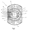
- the joint 1 explained below comprises two tool parts, of which a first in plan view FIG. 1 is reproduced.
- the first tool part 3 has a recess 5 into which a second tool part 7 can be inserted, which is indicated here by a dashed circular line 9.
- Central in the recess 5 is a Clamping cartridge 11 is arranged, which serves to fasten the second tool part 7 on the first tool part 3.
- the second tool part 7 has a hollow shaft, which is inserted into the recess 5, so that the clamping cartridge 11 is arranged in the interior of the hollow shaft and this clamps during manufacture of the connection point 1, so when clamping the two tool parts 3 and 7 in the recess 5 by being radially expanded.
- the hollow shaft of the second tool part 7 has two slots extending in the longitudinal direction of the tool part 7, in which on the one hand a projection 13 and on the other hand a device 15 for effecting a defined angular position engage.
- the projection 13 originates from the inner surface 17 of the recess 5 in the first tool part 3. It is dimensioned such that it practically completely fills the slot predetermined in the hollow shaft of the second tool part 7.
- the side surfaces 19 and 21 of the projection 13 can serve as abutment surfaces for the flanks of the slot in the hollow shaft of the second tool part 7.
- a second slot is provided, in which an elastic element 23 of the device 15 engages.
- the elastic element 23 is firmly clamped in a first region on the first tool part 3 and protrudes with a second region 25 into the recess 5 in such a way that it lies in the path of movement of the second tool part 7 when it is inserted into the recess 5 ,
- the connection point 1 ie when inserting the second tool part 7 into the recess 5 of the first tool part 3
- the second region 25 of the elastic element 23 is reversibly deflected, which causes a restoring force.
- the elastic element 23 is accommodated in a first groove 29 introduced from outside into the wall of the first tool part 3. Parallel to this runs a second groove 31 into which a counterpart 33 is inserted.
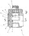
- FIG. 2 shows the first tool part 3 in longitudinal section. Same parts, based on FIG. 1 are explained with the same reference numerals provided, so that in this respect to the description FIG. 1 is referenced.
- the longitudinal section is placed so that the counterpart 33 can be seen in side view. It lies in the second groove 31. Behind the counterpart 33, the elastic element 23 can be seen, the first region, which is covered by the counterpart 33, is arranged in the first groove 29.
- the first, hidden area of the elastic element 23 is, like the counterpart 33, provided with an outer contour whose peripheral surface deviates from the circular shape in cross-section. He is polygonal here. This polygonal contour is intended to ensure that the elastic element 23 is held against rotation in the wall of the first tool part 3 in the first region.
- the pentagonal contour of the counterpart 33, which coincides with that of the first region of the elastic element 23, is shown in FIG FIG. 1 seen.
- FIG. 2 shows a clamping screw 41 which is perpendicular to the extension of the counterpart 33 and the first portion 43 of the elastic member 23 and engages the base body of the first tool part 3 and serves to the first portion of the elastic member 23 and the counterpart 33 rotatably in the first tool part 3 to brace.
- the representation according to FIG. 2 indicates that the second region 25 of the elastic element 23rd protrudes into the recess 5 of the first tool part 3 so that it also projects into the path of movement of the second tool part 7, when the hollow shaft is inserted into the recess 5.
- FIG. 2 indicates that the elastic element 23 is formed as a torsion element and has an essentially L-shaped configuration.
- the first area At the end of the longer leg of the elastic element 23 is the first area, which is clamped in a torque-proof manner behind the counterpart 33 on the first tool part 3.
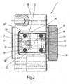
- FIG. 3 shows the first tool part 3 of the connection point 1 in side view.
- the cover plate 35 to see, by the screws 37 and 39, in FIG. 1 are shown, also held by two further screws 37 'and 39'.
- the elastic member 23 indicated, which is housed in the associated first groove 29, also the counterpart 33, which is arranged in the second groove 31.
- the counterpart is shorter than the elastic element 23 and extends only over a region which is also detected by the clamping screw 41. This urges the first portion 43 of the elastic member 23 against the upper edge 45 of the first groove 29 and at the same time the counterpart 33 against the lower edge 47 of the first groove 31.
- FIG. 3 it can be seen that in the wall of the first tool part 3, a first recess 49 is introduced, which intersects the first groove 29. There is also provided a second recess 51 which intersects the first groove 31.
- the first recess 49 Through the first recess 49, the second region 25 of the elastic element 23 protrudes through the wall of the first tool part 3 in its recess 5 and into the path of movement of the second tool part 7 inserted in the recess 5, which is not shown here.
- the second recess 51 serves to displace the elastic element 23, if necessary, and to move it out of the first groove 29 into the second groove 31, whereby the counterpart 33 is also correspondingly displaced into the opposite groove. It is thus possible to ensure by means of the elastic element 23 in a simple manner a defined angular position, regardless of whether the hollow shaft of the second. Tool part 7 to the upper side surface 19 or the lower side surface 21 of the projection 13 should strike.
- the device 15 for effecting a defined angular position can thus be used universally for a right and / or left stop.
- FIG. 4 shows a section along the in FIG. 2 marked line IV-IV.
- the first tool part 3 cover plate 35 which closes the first groove 29 and the second groove 31 and thus holds the first portion 43 of the elastic member and the counterpart 33 against rotation.
- the clamping screw 41 can be seen, which ensures that the first region 43 is securely held and supported against rotation. Due to the special contour of the first region 43 and that of the counterpart 33, which here have V-shaped starting ramps from top to bottom, the conically downwardly tapering head of the clamping screw 41 urges the first region 43 and the counterpart 33 so apart that a rotation of the elastic element 23 is reliably avoided.
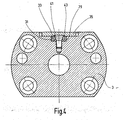
- FIG. 5 clarifies once again the operation of the device 15 within the connection point 1, which is shown here only partially schematically.
- FIG. 5 shows the junction 1 in plan view, as well as in FIG. 1 the case is.
- the second region 25 of the elastic element 23 can clearly be seen, which projects into the recess 5 of the first tool part 3, which is only indicated here, and into the movement path of the second tool part 7, of which the hollow shaft 53 is indicated here.
- the hollow shaft 53 has two slots 55 and 57 extending in its longitudinal direction. In the first slot 55, the second portion 25 of the elastic member 23 projects into the second slot 57, the projection 13 projects, based on FIG. 1 was explained.
- the second Region 25 of the elastic element here has a run-on slope 59 which cooperates with a side surface 61 of the first slot 55 so that acts on the hollow shaft 53 a directed in the direction of arrow 27 force.
- the second portion 25 may be provided at its free end with symmetrical chamfers. It is also possible to provide a mirror-image formed element 23, when a direction opposite to the arrow 27 directed clamping force to be applied.
- the two tool parts After using the device 15, the two tool parts have taken a defined angular position, now a clamping of the two tool parts can be made in the region of the joint 1, in which the collet 11 is activated in a conventional manner and the hollow shaft 53 of the second tool part 7 so expands in that it rests securely against the inner surface of the recess 5.
- connection point 1 During operation of the connection point 1, high torques can be transmitted from the first tool part 3 to the second tool part 7 or vice versa via the projection 13.
- a rotary movement of the tool in the region of the connection point 1 against the Clockwise it is ensured that even under load no relative rotation between the first tool part 3 and the second tool part 7 is given, because by the device 15 a contact of the side surface 63 of the hollow shaft 53 is ensured on the side surface 19 of the projection 13.
- a short pin inserted into the side wall of the first tool part 3 can be used as an elastic element 23 in order to specify a defined angular position of the tool pieces.
- the elastic element 23, as explained here, L-shaped and thus formed as a torsion there is a longer deformation path within the elastic member 23, so that a fatigue fracture can be virtually eliminated.
- the biasing forces can be varied, which are built up in the enforcement of the rotational angular position should.
- a plurality of elastic elements 23 can be distributed over the circumference of the first tool part 3 in order to increase the setting forces.
- at least one elastic element in addition to or instead of the second tool part 7 described here.
- the elastic element can also be arranged on the end-side contact surface of two tool parts, or in this case engage with one or both tool parts in order to achieve a defined rotational angle position.
Landscapes
- Mechanical Engineering (AREA)
- Engineering & Computer Science (AREA)
- Clamps And Clips (AREA)
- Details Of Spanners, Wrenches, And Screw Drivers And Accessories (AREA)
- Jigs For Machine Tools (AREA)
- Harvester Elements (AREA)
- Insertion Pins And Rivets (AREA)
- Springs (AREA)
- Dental Tools And Instruments Or Auxiliary Dental Instruments (AREA)
- Slide Fasteners, Snap Fasteners, And Hook Fasteners (AREA)
- Gyroscopes (AREA)
- Pivots And Pivotal Connections (AREA)
- Led Devices (AREA)
Description
- Die Erfindung betrifft ein Werkzeug mit einer Verbindungsstelle zwischen zwei Werkzeugteilen gemäß Oberbegriff des Anspruchs 1 (siehe z.B.,
EP-0 753 680-A ). - Verbindungsstellen der hier angesprochenen Art sind bekannt. Sie treten im Bereich zweier miteinander verbundener Werkzeugteile auf. Denkbar ist es, dass beispielsweise ein Werkzeug an einer Halterung befestigt wird, die Teil einer Werkzeugmaschine ist oder an dieser angebracht wird. Möglich ist es auch, dass eine Verbindungsstelle der hier angesprochenen Art zwischen einem Werkzeug und einem Zwischenstück, einem Werkzeug und einem Adapter oder zwischen Zwischenstücken und Adaptern gegeben sind. Wesentlich ist, dass im Bereich der Verbindungsstelle zwischen zwei Werkzeugteilen eine definierte Winkellage gegeben ist, so dass bei einem Werkzeugtausch bei der Bearbeitung eines Werkstücks nicht unterschiedliche Maße gegeben sind. Beispielsweise kann ein Werkzeug zur spanabtragenden Bearbeitung, wie zum Beispiel ein Drehwerkzeug oder eine Reibahle, bei Verschleiß der Messerplatte ausgetauscht werden, ohne dass es bei der Weiterbearbeitung des Werkstücks zu Änderungen der Maße der bearbeiteten Bohrungen kommt.
- Zur Einstellung der gewünschten Winkellage werden Vorrichtungen im Bereich von Verbindungsstellen eingesetzt, die eine definierte Positionierung der beiden in der Verbindungsstelle zusammengesetzten Werkzeugteile ermöglicht. Bislang eingesetzte elastische Elemente haben jedoch in einigen Fällen keine ausreichenden Einstellkräfte ergeben, so dass die Positionierung der beiden Werkzeugteile im Bereich der Verbindungsstelle nicht immer optimal war.
- Aufgabe der Erfindung ist es daher, eine Verbindungsstelle der eingangs genannten Art zu schaffen, die diesen Nachteil vermeidet.
- Zur Lösung dieser Aufgabe wird eine Verbindungsstelle vorgeschlagen, die die in Anspruch 1 genannten Merkmale aufweist. Sie zeichnet sich durch eine Vorrichtung zum Bewirken einer definierten Drehwinkellage zwischen den zu verbindenden Werkzeugteilen aus, die ein elastisches Element umfasst. Dieses ist in einem ersten Bereich an einem ersten Werkzeugteil so eingespannt, dass ein zweiter Bereich des elastischen Elements beim Verbinden der Werkzeugteile in die Bewegungsbahn des zweiten Werkzeugteils ragt. Damit wird erreicht, dass beim Zusammenfügen der beiden Werkzeugteile dieser zweite Bereich von dem zweiten Werkzeugteil ausgelenkt und reversibel verformt wird. Diese Verformung führt zu einer Vorspannkraft des im ersten Bereich fest eingespannten elastischen Elements, die eine Relativdrehung der beiden Werkzeugteile bewirkt und damit eine definierte Drehwinkellage einstellt.
- Bevorzugt wird ein Ausführungsbeispiel der Erfindung, das sich dadurch auszeichnet, dass das elastische Element als Torsionselement ausgebildet ist. Damit ist es möglich, die zur Erzwingung der Drehwinkellage erforderlichen Kräfte in einem weiten Bereich zu variieren.
- Weitere Vorteile ergeben sich aus den übrigen Unteransprüchen.
- Die Erfindung wird im Folgenden anhand der Zeichnung näher erläutert. Es zeigen:
- Figur 1
- Eine Draufsicht auf ein erstes Werkzeugteil einer Verbindungsstelle;
- Figur 2
- einen Längsschnitt des in
Figur 1 dargestellten Werkzeugteils; - Figur 3
- eine Seitenansicht des in
Figur 1 dargestellten Werkzeugteils; - Figur 4
- einen Längsschnitt entlang der Linie IV - IV durch das in
Figur 2 dargestellte Werkzeug und - Figur 5
- eine schematische Darstellung einer Draufsicht auf ein erstes und zweites Werkzeugteil einer Verbindungsstelle.
- Die im Folgenden erläuterte Verbindungsstelle 1 umfasst zwei Werkzeugteile, von denen ein erstes in Draufsicht in
Figur 1 wiedergegeben ist. Das erste Werkzeugteil 3 weist eine Ausnehmung 5 auf, in die ein zweites Werkzeugteil 7 einsteckbar ist, das hier durch eine gestrichelte Kreislinie 9 angedeutet ist. Zentral in der Ausnehmung 5 ist eine Spannpatrone 11 angeordnet, die der Befestigung des zweiten Werkzeugteils 7 am ersten Werkzeugteil 3 dient. Das zweite Werkzeugteil 7 weist einen Hohlschaft auf, der in die Ausnehmung 5 eingesteckt wird, so dass die Spannpatrone 11 im Inneren des Hohlschaftes angeordnet ist und diesen bei Herstellung der Verbindungsstelle 1, also beim Verspannen der beiden Werkzeugteile 3 und 7 in der Ausnehmung 5 festspannt, indem dieser radial aufgeweitet wird. - Der Hohlschaft des zweiten Werkzeugteils 7 weist zwei in Längsrichtung des Werkzeugteils 7 verlaufende Schlitze auf, in die einerseits ein Vorsprung 13 und andererseits eine Vorrichtung 15 zum Bewirken einer definierten Drehwinkellage eingreifen. Der Vorsprung 13 entspringt von der Innenfläche 17 der Ausnehmung 5 im ersten Werkzeugteil 3. Er ist so dimensioniert, dass er den im Hohlschaft des zweiten Werkzeugteils 7 vorgegebenen Schlitz praktisch vollständig ausfüllt. Damit können die Seitenflächen 19 und 21 des Vorsprungs 13 als Anlageflächen für die Flanken des Schlitzes im Hohlschaft des zweiten Werkzeugteils 7 dienen.
- Gegenüber dem den Vorsprung 13 aufnehmenden ersten Schlitz im zweiten Werkzeugteil 7 ist ein zweiter Schlitz vorgesehen, in den ein elastisches Element 23 der Vorrichtung 15 eingreift. Das elastische Element 23 ist in einem ersten Bereich an dem ersten Werkzeugteil 3 fest eingespannt und ragt mit einem zweiten Bereich 25 in die Ausnehmung 5 so vor, dass dieser in der Bewegungsbahn des zweiten Werkzeugteils 7 liegt, wenn'es in die Ausnehmung 5 eingesteckt wird. Beim Zusammenfügen der Verbindungsstelle 1, also beim Einstecken des zweiten Werkzeugteils 7 in die Ausnehmung 5 des ersten Werkzeugteils 3, wird der zweite Bereich 25 des elastischen Elements 23 reversibel ausgelenkt, was eine Rückstellkraft bewirkt. Dadurch wird eine hier im Uhrzeigersinn wirkende Kraft aufgebaut, die auf den Hohlschaft des zweiten Werkzeugteils 7 wirkt, was durch einen Pfeil 27 angedeutet ist. Durch die von dem elastischen Element 23 ausgeübte Kraft wird der Hohlschaft des zweiten Werkzeugteils 7 im Uhrzeigersinn verdreht, bis dieser an der oberen Seitenfläche 19 des Vorsprungs 13 anschlägt und damit eine definierte Drehwinkellage zwischen den beiden Werkzeugteilen der Verbindungsstelle 1 gegeben ist. Nachdem diese durch die Vorrichtung 15 vorgegeben ist, wird die Spannpatrone 11 aktiviert, um das zweite Werkzeugteil 7 im ersten Werkzeugteil 3 fest einzuspannen.
- Das elastische Element 23 ist in einer von außen in die Wandung des ersten Werkzeugteils 3 eingebrachten ersten Nut 29 untergebracht. Parallel zu dieser verläuft eine zweite Nut 31, in die ein Gegenstück 33 eingesetzt ist.
- Durch eine Abdeckplatte 35, die von Schrauben 37 und 39 am ersten Werkzeugteil 3 befestigt ist, werden das elastische Element 23 und das Gegenstück 33 fest eingespannt.
-
Figur 2 zeigt das erste Werkzeugteil 3 im Längsschnitt. Gleiche Teile, die anhand vonFigur 1 erläutert wurden, sind mit gleichen Bezugsziffern versehen, so dass insoweit auf die Beschreibung zuFigur 1 verwiesen wird. - Der Längsschnitt ist so gelegt, dass das Gegenstück 33 in Seitenansicht erkennbar ist. Es liegt in der zweiten Nut 31. Hinter dem Gegenstück 33 ist das elastische Element 23 erkennbar, dessen erster Bereich, der durch das Gegenstück 33 verdeckt ist, in der ersten Nut 29 angeordnet ist. Der erste, verdeckte Bereich des elastischen Elements 23 ist, wie das Gegenstück 33 mit einer Außenkontur versehen, dessen Umfangfläche im Querschnitt von der Kreisform abweicht. Er ist hier mehreckig ausgebildet. Diese mehreckige Kontur soll sicherstellen, dass das elastische Element 23 im ersten Bereich verdrehsicher in der Wandung des ersten Werkzeugteils 3 gehalten wird. Die hier fünfeckige Kontur des Gegenstücks 33, die mit der des ersten Bereichs des elastischen Elements 23 übereinstimmt, ist aus der Darstellung gemäß
Figur 1 ersichtlich. Sie ist so gewählt, dass der erste Bereich des elastischen Elements 23 und das Gegenstück 33 verdrehsicher im Grundkörper des ersten Werkzeugteils 3 gehalten werden.Figur 2 zeigt eine Spannschraube 41, die senkrecht zur Erstreckung des Gegenstücks 33 und des ersten Bereichs 43 des elastischen Elements 23 verläuft und in den Grundkörper des ersten Werkzeugteils 3 eingreift und dazu dient, den ersten Bereich des elastischen Elements 23 und das Gegenstück 33 drehfest im ersten Werkzeugteil 3 zu verspannen. - Die Darstellung gemäß
Figur 2 lässt erkennen, dass der zweite Bereich 25 des elastischen Elements 23 in die Ausnehmung 5 des ersten Werkzeugteils 3 so hineinragt, dass es auch in den Bewegungspfad des zweiten Werkzeugteils 7 vorsteht, wenn dessen Hohlschaft in die Ausnehmung 5 eingesteckt wird. -
Figur 2 lässt erkennen, dass das elastische Element 23 als Torsionselement ausgebildet ist und im wesentlichen eine L-förmige Ausgestaltung aufweist. Am Ende des längeren Schenkels des elastischen Elements 23 befindet sich der erste Bereich, der hinter dem Gegenstück 33 drehfest am ersten Werkzeugteil 3 festgespannt ist. Der kürzere Schenkel des elastischen Elements 23, also der zweite Bereich 25, ragt frei beweglich in die Ausnehmung 5, um gegebenenfalls mit dem Hohlschaft des zweiten Werkzeugteils 7 zusammenzuwirken. -
Figur 3 zeigt das erste Werkzeugteil 3 der Verbindungsstelle 1 in Seitenansicht. Deutlich ist hier die Abdeckplatte 35 zu sehen, die von den Schrauben 37 und 39, die inFigur 1 dargestellt sind, gehalten wird, außerdem von zwei weiteren Schrauben 37' und 39'. Gestrichelt ist inFigur 3 das elastische Element 23 angedeutet, das in der zugehörigen ersten Nut 29 untergebracht ist, außerdem das Gegenstück 33, das in der zweiten Nut 31 angeordnet ist. Es wird hier auch deutlich, dass das Gegenstück kürzer ist als das elastische Element 23 und sich nur über einen Bereich erstreckt, der auch von der Spannschraube 41 erfasst wird. Diese drängt den ersten Bereich 43 des elastischen Elements 23 gegen die obere Flanke 45 der ersten Nut 29 und gleichzeitig das Gegenstück 33 gegen die untere Flanke 47 der ersten Nut 31. Da das Gegenstück 33 und insbesondere der erste Bereich 43 des elastischen Elements 23 eine von der Kreisbogenform abweichende Querschnittsfläche aufweist, wird beim Festschrauben der Spannschraube 41 eine drehsichere Verankerung des elastischen Elements 23 im Grundkörper des ersten Werkzeugteils 3 sichergestellt. - In
Figur 3 ist erkennbar, dass in die Wandung des ersten Werkzeugteils 3 eine erste Ausnehmung 49 eingebracht ist, die die erste Nut 29 schneidet. Es ist außerdem eine zweite Ausnehmung 51 vorgesehen, die die erste Nut 31 schneidet. Durch die erste Ausnehmung 49 ragt der zweite Bereich 25 des elastischen Elements 23 durch die Wandung des ersten Werkzeugteils 3 in dessen Ausnehmung 5 und in den Bewegungspfad des in die Ausnehmung 5 eingesteckten zweiten Werkzeugteils 7, das hier nicht dargestellt ist. - Die zweite Ausnehmung 51 dient dazu, dass elastische Element 23 gegebenenfalls zu versetzen und aus der ersten Nut 29 in die zweite Nut 31 zu versetzen, wobei auch das Gegenstück 33 entsprechend in die gegenüberliegende Nut verlagert wird. Es ist damit möglich, mittels des elastischen Elements 23 auf einfache Weise eine definierte Drehwinkellage zu gewährleisten, unabhängig davon, ob der Hohlschaft des zweiten. Werkzeugteils 7 an die obere Seitenfläche 19 oder die untere Seitenfläche 21 des Vorsprungs 13 anschlagen soll. Die Vorrichtung 15 zum Bewirken einer definierten Drehwinkellage kann also universell für einen Rechts- und/oder Linksanschlag verwendet werden.
-
Figur 4 zeigt einen Schnitt entlang der inFigur 2 eingezeichneten Linie IV-IV. Deutlich erkennbar ist hier die am ersten Werkzeugteil 3 verankerte Abdeckplatte 35, die die erste Nut 29 und die zweite Nut 31 abschließt und damit den ersten Bereich 43 des elastischen Elements und das Gegenstück 33 verdrehsicher hält. Zusätzlich ist hier die Spannschraube 41 erkennbar, die dafür sorgt, dass der erste Bereich 43 sicher gehalten und gegen Verdrehen abgestützt ist. Durch die spezielle Kontur des ersten Bereichs 43 und die des Gegenstücks 33, die hier sich von oben nach unten V-förmig erstreckende Anlaufschrägen aufweisen, drängt der sich konisch nach unten verjüngende Kopf der Spannschraube 41 den ersten Bereich 43 und das Gegenstück 33 so auseinander, dass eine Verdrehung des elastischen Elements 23 sicher vermieden wird. -
Figur 5 verdeutlicht noch einmal die Funktionsweise der Vorrichtung 15 innerhalb der Verbindungsstelle 1, die hier nur zum Teil schematisch wiedergegeben ist.Figur 5 zeigt die Verbindungsstelle 1 in Draufsicht, wie dies auch inFigur 1 der Fall ist. Deutlich ist der zweite Bereich 25 des elastischen Elements 23 erkennbar, der in die Ausnehmung 5 des hier nur angedeuteten ersten Werkzeugteils 3 und in die Bewegungsbahn des zweiten Werkzeugteils 7 ragt, von dem hier der Hohlschaft 53 angedeutet ist. Es ist hier erkennbar, dass der Hohlschaft 53 zwei in dessen Längsrichtung verlaufende Schlitze 55 und 57 aufweist. In den ersten Schlitz 55 ragt der zweite Bereich 25 des elastischen Elements 23, in den zweiten Schlitz 57 springt der Vorsprung 13 vor, der anhand vonFigur 1 erläutert wurde. Der zweite Bereich 25 des elastischen Elements weist hier eine Anlaufschräge 59 auf, die mit einer Seitenfläche 61 des ersten Schlitzes 55 so zusammenwirkt, dass auf den Hohlschaft 53 eine in Richtung des Pfeils 27 gerichtete Kraft wirkt. Diese führt dazu, dass die Seitenfläche 63 des zweiten Schlitzes 57 an der Seitenfläche 19 des Vorsprungs 13 anliegt und damit eine definierte Drehwinkellage zwischen dem Hohlschaft 53 des zweiten Werkzeugteils 7 und dem Vorsprung 13 des ersten Werkzeugteils 3 gegeben ist. Bei einer universellen Verwendung des elastischen Elements 23 für Rechts- und Linksanschlag des Hohlschafts 53 am Vorsprung 13 kann der zweite Bereich 25 an seinem freien Ende mit symmetrischen Anlaufschrägen versehen werden. Es ist überdies möglichein spiegelbildlich ausgebildetes Element 23 vorzusehen, wenn eine entgegengesetzt zum Pfeil 27 gerichtete Verspannkraft aufgebracht werden soll. - Nachdem mit Hilfe der Vorrichtung 15 die beiden Werkzeugteile eine definierte Drehwinkellage eingenommen haben, kann nun im Bereich der Verbindungsstelle 1 eine Verspannung der beiden Werkzeugteile vorgenommen werden, in dem die Spannpatrone 11 auf übliche Weise aktiviert wird und den Hohlschaft 53 des zweiten Werkzeugteils 7 so ausdehnt, dass dieser sicher an der Innenfläche der Ausnehmung 5 anliegt.
- Im Betrieb der Verbindungsstelle 1 können über den Vorsprung 13 hohe Drehmomente vom ersten Werkzeugteil 3 auf das zweite Werkzeugteil 7 oder umgekehrt übertragen werden. Bei einer Drehbewegung des Werkzeugs im Bereich der Verbindungsstelle 1 gegen den Uhrzeigersinn ist sichergestellt, dass auch unter Belastung keine Relativdrehung zwischen dem ersten Werkzeugteil 3 und dem zweiten Werkzeugteil 7 gegeben ist, weil durch die Vorrichtung 15 eine Anlage der Seitenfläche 63 des Hohlschafts 53 an der Seitenfläche 19 des Vorsprungs 13 gewährleistet ist.
- Aus der Funktionsweise der Vorrichtung 15 ist ersichtlich, dass grundsätzlich ein kurzer in die Seitenwand des ersten Werkzeugteils 3 eingesetzter Stift als elastisches Element 23 Verwendung finden kann, um eine definierte Drehwinkellage der Werkzeugstücke vorzugeben. Wird jedoch das elastische Element 23, wie hier erläutert, L-förmig und damit als Torsionselement ausgebildet, ergibt sich ein längerer Verformungsweg innerhalb des elastischen Elements 23, so dass ein Ermüdungsbruch praktisch ausgeschlossen werden kann. Außerdem können durch die Wahl der Länge und/oder des Durchmessers des in Längsrichtung der Verbindungsstelle 1 verlaufenden Schenkels des elastischen Elements 23, oder durch Wahl des Materials der vorzugsweise aus Metall hergestellten Elements 23 die Vorspannkräfte variiert werden, die bei der Erzwingung der Drehwinkellage aufgebaut werden sollen. Wesentlich ist also, dass das elastische Element 23 beim Zusammenfügen der der Verbindungsstelle 1 zugeordneten Werkzeugteile 3, 7 ausgelenkt und reversibel verformt wird. Durch die Rückstellkräfte des elastischen Elements 23 findet eine Relativdrehung, zwischen den Werkzeugteilen 3, 7 statt, so dass eine definierte Drehwinkellage gewährleistet ist.
- Nach allem zeigt sich auch, dass über den Umfang des ersten Werkzeugteils 3 mehrere elastische Elemente 23 verteilt werden können, um die Einstellkräfte zu erhöhen. Schließlich ist es auch denkbar, mindestens ein elastisches Element zusätzlich oder statt der hier beschriebenen am zweiten Werkzeugteil 7 vorzusehen. Im übrigen kann das elastische Element auch an der stirnseitigen Berührungsfläche zweier Werkzeugteile angeordnet sein, oder hier mit einem oder beiden Werkzeugteile in Eingriff treffen, um eine definierte Drehwinkellage zu erreichen.
Claims (11)
- Werkzeug mit zwei Werkzeugteilen, die im Bereich einer Verbindungsstelle miteinander verbunden sind und eine Vorrichtung mit einem elastischen Element umfassen, die eine definierte Drehwinkellage zwischen den Werkzeugteilen bewirkt, dadurch gekennzeichnet, dass das elastische Element (23) in einem ersten Bereich (43) an dem ersten Werkzeugteil (3) so eingespannt ist, dass ein zweiter Bereich (25) des elastischen Elements (23) beim Verbinden der Werkzeugteile (3,7) in die Bewegungsbahn des zweiten Werkzeugteils (7) ragt, so dass er von diesem ausgelenkt und reversibel verformt wird.
- Werkzeug nach Anspruch 1, dadurch gekennzeichnet, dass das elastische Element (23) als Torsionselement ausgebildet ist.
- Werkzeug nach Anspruch 1 oder 2, dadurch gekennzeichnet, dass das elastische Element (23) L-förmig ausgebildet ist und einen in den Verbindungsbereich zwischen dem ersten und zweiten Werkzeugteil (3,7) ragenden Vorsprung (25) aufweist.
- Werkzeug nach einem der vorhergehenden Ansprüche, dadurch gekennzeichnet, dass das elastische Element (23) in dem am ersten Werkzeugteil (3) festgespannten ersten Bereich (43) mindestens einen Abschnitt aufweist, dessen Umfangsfläche im Querschnitt von der Kreisform abweicht.
- Werkzeug nach einem der vorhergehenden Ansprüche, dadurch gekennzeichnet, dass das elastische Element (23) im ersten Bereich (43) einen im Querschnitt mehreckigen Abschnitt aufweist.
- Werkzeug nach einem der vorhergehenden Ansprüche, dadurch gekennzeichnet, dass das erste Werkzeugteil (3) einen Teil des zweiten Werkzeugteils (7) aufnehmenden Ausnehmung (5) aufweist.
- Werkzeug nach einem der vorhergehenden Ansprüche, dadurch gekennzeichnet, dass das elastische Element (23) in die Wandung des ersten Werkzeugteils (3) einsetzbar ist.
- Werkzeug nach einem der Ansprüche 6-7, dadurch gekennzeichnet, dass der Vorsprung des elastischen Elements (23) in der Wandung des ersten Werkzeugteils (3) angeordnet ist und in das Innere der Ausnehmung (5) ragt.
- Werkzeug nach einem der vorhergehenden Ansprüche dadurch gekennzeichnet, dass in die Wandung des ersten Werkzeugteils (3) zwei Nuten (29,31) zur Aufnahme eines elastischen Elements (23) angeordnet sind.
- Werkzeug nach Anspruch 9, dadurch gekennzeichnet, dass zumindest die erste Nut (29) eine die Wandung des ersten Werkzeugteils (3) durchdringende Ausnehmung (49) schneidet.
- Werkzeug nach einem der vorhergehenden Ansprüche, dadurch gekennzeichnet, dass in die Wandung des ersten Werkzeugteils (3) ein dem elastischen Element (23) zugeordneten Gegenstück (33) einsetzbar ist.
Applications Claiming Priority (2)
| Application Number | Priority Date | Filing Date | Title |
|---|---|---|---|
| DE10114746A DE10114746A1 (de) | 2001-03-22 | 2001-03-22 | Verbindungsstelle |
| DE10114746 | 2001-03-22 |
Publications (2)
| Publication Number | Publication Date |
|---|---|
| EP1243803A1 EP1243803A1 (de) | 2002-09-25 |
| EP1243803B1 true EP1243803B1 (de) | 2009-01-07 |
Family
ID=7679043
Family Applications (1)
| Application Number | Title | Priority Date | Filing Date |
|---|---|---|---|
| EP02004826A Expired - Lifetime EP1243803B1 (de) | 2001-03-22 | 2002-03-02 | Verbindungsstelle zwischen zwei Werkzeugteilen |
Country Status (6)
| Country | Link |
|---|---|
| US (1) | US6776553B2 (de) |
| EP (1) | EP1243803B1 (de) |
| JP (1) | JP4074112B2 (de) |
| AT (1) | ATE420300T1 (de) |
| BR (1) | BR0200880B1 (de) |
| DE (2) | DE10114746A1 (de) |
Families Citing this family (1)
| Publication number | Priority date | Publication date | Assignee | Title |
|---|---|---|---|---|
| DE102005049615A1 (de) * | 2005-05-25 | 2007-06-28 | MAPAL Fabrik für Präzisionswerkzeuge Dr. Kress KG | ZB-Klickraster |
Family Cites Families (7)
| Publication number | Priority date | Publication date | Assignee | Title |
|---|---|---|---|---|
| JPS6024322B2 (ja) * | 1978-06-15 | 1985-06-12 | 株式会社松井製作所 | 連結装置 |
| JPS59214531A (ja) * | 1983-05-18 | 1984-12-04 | N T Tool Kk | 保持具 |
| JP3341961B2 (ja) * | 1994-02-28 | 2002-11-05 | 株式会社ユニシアジェックス | 軸継手構造 |
| DE19525463A1 (de) | 1995-07-14 | 1997-01-16 | Mapal Fab Praezision | Verbindungsstelle |
| US5807180A (en) * | 1997-08-28 | 1998-09-15 | Dana Corporation | Constant velocity universal joint shaft and inner race combination |
| JP2001150269A (ja) * | 1999-11-29 | 2001-06-05 | Big Alpha Kk | 工具ホルダーにおける工具位置決め部材と工具ホルダー |
| DE29922642U1 (de) * | 1999-12-24 | 2000-02-24 | Röhm GmbH, 89567 Sontheim | Spannvorrichtung für einen Hohlschaft |
-
2001
- 2001-03-22 DE DE10114746A patent/DE10114746A1/de not_active Ceased
-
2002
- 2002-03-02 DE DE50213185T patent/DE50213185D1/de not_active Expired - Lifetime
- 2002-03-02 EP EP02004826A patent/EP1243803B1/de not_active Expired - Lifetime
- 2002-03-02 AT AT02004826T patent/ATE420300T1/de not_active IP Right Cessation
- 2002-03-18 US US10/100,447 patent/US6776553B2/en not_active Expired - Lifetime
- 2002-03-21 BR BRPI0200880-7A patent/BR0200880B1/pt not_active IP Right Cessation
- 2002-03-22 JP JP2002081125A patent/JP4074112B2/ja not_active Expired - Fee Related
Also Published As
| Publication number | Publication date |
|---|---|
| ATE420300T1 (de) | 2009-01-15 |
| JP2002346869A (ja) | 2002-12-04 |
| US20020152853A1 (en) | 2002-10-24 |
| BR0200880B1 (pt) | 2010-10-19 |
| BR0200880A (pt) | 2003-03-11 |
| DE50213185D1 (de) | 2009-02-26 |
| EP1243803A1 (de) | 2002-09-25 |
| DE10114746A1 (de) | 2002-10-24 |
| US6776553B2 (en) | 2004-08-17 |
| JP4074112B2 (ja) | 2008-04-09 |
Similar Documents
| Publication | Publication Date | Title |
|---|---|---|
| EP0625395B1 (de) | Bohrwerkzeug für metallische Werkstoffe | |
| DE60132455T2 (de) | Drehendes werkzeug mit einem ersetzbaren schneideinsatz an einem ende | |
| DE69928548T2 (de) | Bohrwerkzeugzusammenbau | |
| EP0385280B1 (de) | Innendrehmeissel | |
| DE20114319U1 (de) | Einstellungsmechanismus | |
| DE2608809C3 (de) | Spitzbohrwerkzeug | |
| DE3605569A1 (de) | Schluesselloses bohrfutter sowie verfahren zur herstellung von schluessellosen bohrfuttern | |
| DE3031216C2 (de) | Spannfutter für Gewindebohrer | |
| EP1213081A1 (de) | Werkzeug zur spanenden Feinbearbeitung von Werkstücken | |
| EP0381924B1 (de) | Reibahle | |
| EP0353436B1 (de) | Einstellvorrichtung, insbesondere für Werkzeuge | |
| DE102008063127A1 (de) | Werkzeug mit einem lösbar gespannten Schneidkörper | |
| EP0410104B1 (de) | Zerspanungswerkzeug | |
| DE102013206093B4 (de) | Werkzeugkassette zum Einsetzen in einem Kassettensitz sowie Werkzeug mit einem Kassettensitz für eine derartige Werkzeugkassette | |
| EP2283972B1 (de) | Fixierelement | |
| DE102015119431B4 (de) | Lochsäge | |
| DE20206516U1 (de) | Spannvorrichtung | |
| DE2533495B2 (de) | Bohrstange | |
| DE3029133C2 (de) | Werkzeughalter | |
| EP1243803B1 (de) | Verbindungsstelle zwischen zwei Werkzeugteilen | |
| EP0033086B1 (de) | Bohrwerkzeug mit einem Wendebohrmesser | |
| DE10108103B9 (de) | Maschinenwerkzeug mit verstellbarer Schneidplatte | |
| DE2718787C2 (de) | Fräsmesserkopf | |
| DE102021123121B4 (de) | Werkstückanschlag und Spannvorrichtung mit Werkstückanschlag | |
| DE69509763T2 (de) | Schneidwerkzeugzusammenbau und schneideinsatz |
Legal Events
| Date | Code | Title | Description |
|---|---|---|---|
| PUAI | Public reference made under article 153(3) epc to a published international application that has entered the european phase |
Free format text: ORIGINAL CODE: 0009012 |
|
| AK | Designated contracting states |
Kind code of ref document: A1 Designated state(s): AT BE CH CY DE DK ES FI FR GB GR IE IT LI LU MC NL PT SE TR |
|
| AX | Request for extension of the european patent |
Free format text: AL;LT;LV;MK;RO;SI |
|
| RIN1 | Information on inventor provided before grant (corrected) |
Inventor name: DER ERFINDER HAT AUF SEINE NENNUNG VERZICHTET. |
|
| 17P | Request for examination filed |
Effective date: 20030325 |
|
| AKX | Designation fees paid |
Designated state(s): AT BE CH CY DE DK ES FI FR GB GR IE IT LI LU MC NL PT SE TR |
|
| 17Q | First examination report despatched |
Effective date: 20080110 |
|
| GRAP | Despatch of communication of intention to grant a patent |
Free format text: ORIGINAL CODE: EPIDOSNIGR1 |
|
| GRAS | Grant fee paid |
Free format text: ORIGINAL CODE: EPIDOSNIGR3 |
|
| GRAA | (expected) grant |
Free format text: ORIGINAL CODE: 0009210 |
|
| AK | Designated contracting states |
Kind code of ref document: B1 Designated state(s): AT BE CH CY DE DK ES FI FR GB GR IE IT LI LU MC NL PT SE TR |
|
| REG | Reference to a national code |
Ref country code: GB Ref legal event code: FG4D Free format text: NOT ENGLISH |
|
| REG | Reference to a national code |
Ref country code: CH Ref legal event code: EP |
|
| REG | Reference to a national code |
Ref country code: CH Ref legal event code: NV Representative=s name: TROESCH SCHEIDEGGER WERNER AG |
|
| REG | Reference to a national code |
Ref country code: IE Ref legal event code: FG4D Free format text: LANGUAGE OF EP DOCUMENT: GERMAN |
|
| REF | Corresponds to: |
Ref document number: 50213185 Country of ref document: DE Date of ref document: 20090226 Kind code of ref document: P |
|
| REG | Reference to a national code |
Ref country code: SE Ref legal event code: TRGR |
|
| PG25 | Lapsed in a contracting state [announced via postgrant information from national office to epo] |
Ref country code: NL Free format text: LAPSE BECAUSE OF FAILURE TO SUBMIT A TRANSLATION OF THE DESCRIPTION OR TO PAY THE FEE WITHIN THE PRESCRIBED TIME-LIMIT Effective date: 20090107 |
|
| NLV1 | Nl: lapsed or annulled due to failure to fulfill the requirements of art. 29p and 29m of the patents act | ||
| PG25 | Lapsed in a contracting state [announced via postgrant information from national office to epo] |
Ref country code: FI Free format text: LAPSE BECAUSE OF FAILURE TO SUBMIT A TRANSLATION OF THE DESCRIPTION OR TO PAY THE FEE WITHIN THE PRESCRIBED TIME-LIMIT Effective date: 20090107 Ref country code: ES Free format text: LAPSE BECAUSE OF FAILURE TO SUBMIT A TRANSLATION OF THE DESCRIPTION OR TO PAY THE FEE WITHIN THE PRESCRIBED TIME-LIMIT Effective date: 20090418 |
|
| REG | Reference to a national code |
Ref country code: IE Ref legal event code: FD4D |
|
| PG25 | Lapsed in a contracting state [announced via postgrant information from national office to epo] |
Ref country code: PT Free format text: LAPSE BECAUSE OF FAILURE TO SUBMIT A TRANSLATION OF THE DESCRIPTION OR TO PAY THE FEE WITHIN THE PRESCRIBED TIME-LIMIT Effective date: 20090608 |
|
| BERE | Be: lapsed |
Owner name: MAPAL FABRIK FUR PRAZISIONSWERKZEUGE DR. KRESS K. Effective date: 20090331 |
|
| PG25 | Lapsed in a contracting state [announced via postgrant information from national office to epo] |
Ref country code: IE Free format text: LAPSE BECAUSE OF FAILURE TO SUBMIT A TRANSLATION OF THE DESCRIPTION OR TO PAY THE FEE WITHIN THE PRESCRIBED TIME-LIMIT Effective date: 20090107 Ref country code: DK Free format text: LAPSE BECAUSE OF FAILURE TO SUBMIT A TRANSLATION OF THE DESCRIPTION OR TO PAY THE FEE WITHIN THE PRESCRIBED TIME-LIMIT Effective date: 20090107 Ref country code: MC Free format text: LAPSE BECAUSE OF NON-PAYMENT OF DUE FEES Effective date: 20090331 |
|
| PLBE | No opposition filed within time limit |
Free format text: ORIGINAL CODE: 0009261 |
|
| STAA | Information on the status of an ep patent application or granted ep patent |
Free format text: STATUS: NO OPPOSITION FILED WITHIN TIME LIMIT |
|
| 26N | No opposition filed |
Effective date: 20091008 |
|
| PG25 | Lapsed in a contracting state [announced via postgrant information from national office to epo] |
Ref country code: BE Free format text: LAPSE BECAUSE OF NON-PAYMENT OF DUE FEES Effective date: 20090331 |
|
| PG25 | Lapsed in a contracting state [announced via postgrant information from national office to epo] |
Ref country code: AT Free format text: LAPSE BECAUSE OF NON-PAYMENT OF DUE FEES Effective date: 20090302 |
|
| PG25 | Lapsed in a contracting state [announced via postgrant information from national office to epo] |
Ref country code: LU Free format text: LAPSE BECAUSE OF NON-PAYMENT OF DUE FEES Effective date: 20090302 |
|
| PG25 | Lapsed in a contracting state [announced via postgrant information from national office to epo] |
Ref country code: TR Free format text: LAPSE BECAUSE OF FAILURE TO SUBMIT A TRANSLATION OF THE DESCRIPTION OR TO PAY THE FEE WITHIN THE PRESCRIBED TIME-LIMIT Effective date: 20090107 |
|
| PG25 | Lapsed in a contracting state [announced via postgrant information from national office to epo] |
Ref country code: CY Free format text: LAPSE BECAUSE OF FAILURE TO SUBMIT A TRANSLATION OF THE DESCRIPTION OR TO PAY THE FEE WITHIN THE PRESCRIBED TIME-LIMIT Effective date: 20090107 |
|
| PG25 | Lapsed in a contracting state [announced via postgrant information from national office to epo] |
Ref country code: GR Free format text: LAPSE BECAUSE OF FAILURE TO SUBMIT A TRANSLATION OF THE DESCRIPTION OR TO PAY THE FEE WITHIN THE PRESCRIBED TIME-LIMIT Effective date: 20090107 |
|
| REG | Reference to a national code |
Ref country code: FR Ref legal event code: PLFP Year of fee payment: 14 |
|
| PGFP | Annual fee paid to national office [announced via postgrant information from national office to epo] |
Ref country code: CH Payment date: 20150319 Year of fee payment: 14 |
|
| PGFP | Annual fee paid to national office [announced via postgrant information from national office to epo] |
Ref country code: FR Payment date: 20150319 Year of fee payment: 14 Ref country code: GB Payment date: 20150319 Year of fee payment: 14 Ref country code: SE Payment date: 20150319 Year of fee payment: 14 |
|
| PGFP | Annual fee paid to national office [announced via postgrant information from national office to epo] |
Ref country code: IT Payment date: 20150326 Year of fee payment: 14 |
|
| PGFP | Annual fee paid to national office [announced via postgrant information from national office to epo] |
Ref country code: DE Payment date: 20160324 Year of fee payment: 15 |
|
| REG | Reference to a national code |
Ref country code: CH Ref legal event code: PL |
|
| REG | Reference to a national code |
Ref country code: SE Ref legal event code: EUG |
|
| GBPC | Gb: european patent ceased through non-payment of renewal fee |
Effective date: 20160302 |
|
| PG25 | Lapsed in a contracting state [announced via postgrant information from national office to epo] |
Ref country code: SE Free format text: LAPSE BECAUSE OF NON-PAYMENT OF DUE FEES Effective date: 20160303 |
|
| REG | Reference to a national code |
Ref country code: FR Ref legal event code: ST Effective date: 20161130 |
|
| PG25 | Lapsed in a contracting state [announced via postgrant information from national office to epo] |
Ref country code: GB Free format text: LAPSE BECAUSE OF NON-PAYMENT OF DUE FEES Effective date: 20160302 Ref country code: LI Free format text: LAPSE BECAUSE OF NON-PAYMENT OF DUE FEES Effective date: 20160331 Ref country code: FR Free format text: LAPSE BECAUSE OF NON-PAYMENT OF DUE FEES Effective date: 20160331 Ref country code: CH Free format text: LAPSE BECAUSE OF NON-PAYMENT OF DUE FEES Effective date: 20160331 |
|
| PG25 | Lapsed in a contracting state [announced via postgrant information from national office to epo] |
Ref country code: IT Free format text: LAPSE BECAUSE OF NON-PAYMENT OF DUE FEES Effective date: 20160302 |
|
| REG | Reference to a national code |
Ref country code: DE Ref legal event code: R119 Ref document number: 50213185 Country of ref document: DE |
|
| PG25 | Lapsed in a contracting state [announced via postgrant information from national office to epo] |
Ref country code: DE Free format text: LAPSE BECAUSE OF NON-PAYMENT OF DUE FEES Effective date: 20171003 |