EP1243803A1 - Verbindungsstelle zwischen zwei Werkzeugteilen - Google Patents
Verbindungsstelle zwischen zwei Werkzeugteilen Download PDFInfo
- Publication number
- EP1243803A1 EP1243803A1 EP02004826A EP02004826A EP1243803A1 EP 1243803 A1 EP1243803 A1 EP 1243803A1 EP 02004826 A EP02004826 A EP 02004826A EP 02004826 A EP02004826 A EP 02004826A EP 1243803 A1 EP1243803 A1 EP 1243803A1
- Authority
- EP
- European Patent Office
- Prior art keywords
- tool part
- elastic element
- tool
- connection point
- point according
- Prior art date
- Legal status (The legal status is an assumption and is not a legal conclusion. Google has not performed a legal analysis and makes no representation as to the accuracy of the status listed.)
- Granted
Links
Images


Classifications
-
- B—PERFORMING OPERATIONS; TRANSPORTING
- B23—MACHINE TOOLS; METAL-WORKING NOT OTHERWISE PROVIDED FOR
- B23B—TURNING; BORING
- B23B31/00—Chucks; Expansion mandrels; Adaptations thereof for remote control
- B23B31/02—Chucks
- B23B31/026—Chucks the radial or angular position of the tool being adjustable
-
- Y—GENERAL TAGGING OF NEW TECHNOLOGICAL DEVELOPMENTS; GENERAL TAGGING OF CROSS-SECTIONAL TECHNOLOGIES SPANNING OVER SEVERAL SECTIONS OF THE IPC; TECHNICAL SUBJECTS COVERED BY FORMER USPC CROSS-REFERENCE ART COLLECTIONS [XRACs] AND DIGESTS
- Y10—TECHNICAL SUBJECTS COVERED BY FORMER USPC
- Y10T—TECHNICAL SUBJECTS COVERED BY FORMER US CLASSIFICATION
- Y10T279/00—Chucks or sockets
- Y10T279/17—Socket type
- Y10T279/17666—Radially reciprocating jaws
- Y10T279/17675—Transverse-screw actuated
-
- Y—GENERAL TAGGING OF NEW TECHNOLOGICAL DEVELOPMENTS; GENERAL TAGGING OF CROSS-SECTIONAL TECHNOLOGIES SPANNING OVER SEVERAL SECTIONS OF THE IPC; TECHNICAL SUBJECTS COVERED BY FORMER USPC CROSS-REFERENCE ART COLLECTIONS [XRACs] AND DIGESTS
- Y10—TECHNICAL SUBJECTS COVERED BY FORMER USPC
- Y10T—TECHNICAL SUBJECTS COVERED BY FORMER US CLASSIFICATION
- Y10T403/00—Joints and connections
- Y10T403/16—Joints and connections with adjunctive protector, broken parts retainer, repair, assembly or disassembly feature
- Y10T403/1616—Position or guide means
-
- Y—GENERAL TAGGING OF NEW TECHNOLOGICAL DEVELOPMENTS; GENERAL TAGGING OF CROSS-SECTIONAL TECHNOLOGIES SPANNING OVER SEVERAL SECTIONS OF THE IPC; TECHNICAL SUBJECTS COVERED BY FORMER USPC CROSS-REFERENCE ART COLLECTIONS [XRACs] AND DIGESTS
- Y10—TECHNICAL SUBJECTS COVERED BY FORMER USPC
- Y10T—TECHNICAL SUBJECTS COVERED BY FORMER US CLASSIFICATION
- Y10T403/00—Joints and connections
- Y10T403/40—Radially spaced members joined by independent coupling
-
- Y—GENERAL TAGGING OF NEW TECHNOLOGICAL DEVELOPMENTS; GENERAL TAGGING OF CROSS-SECTIONAL TECHNOLOGIES SPANNING OVER SEVERAL SECTIONS OF THE IPC; TECHNICAL SUBJECTS COVERED BY FORMER USPC CROSS-REFERENCE ART COLLECTIONS [XRACs] AND DIGESTS
- Y10—TECHNICAL SUBJECTS COVERED BY FORMER USPC
- Y10T—TECHNICAL SUBJECTS COVERED BY FORMER US CLASSIFICATION
- Y10T403/00—Joints and connections
- Y10T403/40—Radially spaced members joined by independent coupling
- Y10T403/405—Flexible intermediate member
-
- Y—GENERAL TAGGING OF NEW TECHNOLOGICAL DEVELOPMENTS; GENERAL TAGGING OF CROSS-SECTIONAL TECHNOLOGIES SPANNING OVER SEVERAL SECTIONS OF THE IPC; TECHNICAL SUBJECTS COVERED BY FORMER USPC CROSS-REFERENCE ART COLLECTIONS [XRACs] AND DIGESTS
- Y10—TECHNICAL SUBJECTS COVERED BY FORMER USPC
- Y10T—TECHNICAL SUBJECTS COVERED BY FORMER US CLASSIFICATION
- Y10T403/00—Joints and connections
- Y10T403/70—Interfitted members
- Y10T403/7018—Interfitted members including separably interposed key
-
- Y—GENERAL TAGGING OF NEW TECHNOLOGICAL DEVELOPMENTS; GENERAL TAGGING OF CROSS-SECTIONAL TECHNOLOGIES SPANNING OVER SEVERAL SECTIONS OF THE IPC; TECHNICAL SUBJECTS COVERED BY FORMER USPC CROSS-REFERENCE ART COLLECTIONS [XRACs] AND DIGESTS
- Y10—TECHNICAL SUBJECTS COVERED BY FORMER USPC
- Y10T—TECHNICAL SUBJECTS COVERED BY FORMER US CLASSIFICATION
- Y10T403/00—Joints and connections
- Y10T403/70—Interfitted members
- Y10T403/7018—Interfitted members including separably interposed key
- Y10T403/7021—Axially extending
- Y10T403/7022—Resilient
-
- Y—GENERAL TAGGING OF NEW TECHNOLOGICAL DEVELOPMENTS; GENERAL TAGGING OF CROSS-SECTIONAL TECHNOLOGIES SPANNING OVER SEVERAL SECTIONS OF THE IPC; TECHNICAL SUBJECTS COVERED BY FORMER USPC CROSS-REFERENCE ART COLLECTIONS [XRACs] AND DIGESTS
- Y10—TECHNICAL SUBJECTS COVERED BY FORMER USPC
- Y10T—TECHNICAL SUBJECTS COVERED BY FORMER US CLASSIFICATION
- Y10T408/00—Cutting by use of rotating axially moving tool
- Y10T408/94—Tool-support
- Y10T408/95—Tool-support with tool-retaining means
-
- Y—GENERAL TAGGING OF NEW TECHNOLOGICAL DEVELOPMENTS; GENERAL TAGGING OF CROSS-SECTIONAL TECHNOLOGIES SPANNING OVER SEVERAL SECTIONS OF THE IPC; TECHNICAL SUBJECTS COVERED BY FORMER USPC CROSS-REFERENCE ART COLLECTIONS [XRACs] AND DIGESTS
- Y10—TECHNICAL SUBJECTS COVERED BY FORMER USPC
- Y10T—TECHNICAL SUBJECTS COVERED BY FORMER US CLASSIFICATION
- Y10T409/00—Gear cutting, milling, or planing
- Y10T409/30—Milling
- Y10T409/309352—Cutter spindle or spindle support
- Y10T409/309408—Cutter spindle or spindle support with cutter holder
- Y10T409/309464—Cutter spindle or spindle support with cutter holder and draw bar
-
- Y—GENERAL TAGGING OF NEW TECHNOLOGICAL DEVELOPMENTS; GENERAL TAGGING OF CROSS-SECTIONAL TECHNOLOGIES SPANNING OVER SEVERAL SECTIONS OF THE IPC; TECHNICAL SUBJECTS COVERED BY FORMER USPC CROSS-REFERENCE ART COLLECTIONS [XRACs] AND DIGESTS
- Y10—TECHNICAL SUBJECTS COVERED BY FORMER USPC
- Y10T—TECHNICAL SUBJECTS COVERED BY FORMER US CLASSIFICATION
- Y10T409/00—Gear cutting, milling, or planing
- Y10T409/30—Milling
- Y10T409/30952—Milling with cutter holder
-
- Y—GENERAL TAGGING OF NEW TECHNOLOGICAL DEVELOPMENTS; GENERAL TAGGING OF CROSS-SECTIONAL TECHNOLOGIES SPANNING OVER SEVERAL SECTIONS OF THE IPC; TECHNICAL SUBJECTS COVERED BY FORMER USPC CROSS-REFERENCE ART COLLECTIONS [XRACs] AND DIGESTS
- Y10—TECHNICAL SUBJECTS COVERED BY FORMER USPC
- Y10T—TECHNICAL SUBJECTS COVERED BY FORMER US CLASSIFICATION
- Y10T82/00—Turning
- Y10T82/25—Lathe
- Y10T82/2585—Tool rest
- Y10T82/2589—Quick release tool or holder clamp
-
- Y—GENERAL TAGGING OF NEW TECHNOLOGICAL DEVELOPMENTS; GENERAL TAGGING OF CROSS-SECTIONAL TECHNOLOGIES SPANNING OVER SEVERAL SECTIONS OF THE IPC; TECHNICAL SUBJECTS COVERED BY FORMER USPC CROSS-REFERENCE ART COLLECTIONS [XRACs] AND DIGESTS
- Y10—TECHNICAL SUBJECTS COVERED BY FORMER USPC
- Y10T—TECHNICAL SUBJECTS COVERED BY FORMER US CLASSIFICATION
- Y10T82/00—Turning
- Y10T82/25—Lathe
- Y10T82/2585—Tool rest
- Y10T82/2591—Tool post
Definitions
- the invention relates to a connection point between two tool parts according to the preamble of the claim 1.
- junctions of the type mentioned here are known. They occur in the area of two with each other connected tool parts. It is conceivable that for example, a tool attached to a bracket that is part of a machine tool or attached to it. It is possible also that a liaison office of the one addressed here Kind of between a tool and a Adapter, a tool and an adapter or between intermediate pieces and adapters are. It is essential that in the area of the connection point a defined between two tool parts Angular position is given, so that at one Tool exchange when machining a workpiece there are no different dimensions. For example can be a tool for chip removal Machining, such as a turning tool or a reamer, exchanged when the cutter insert is worn be without it being further processed of the workpiece to change the dimensions of the machined holes comes.
- a tool for chip removal Machining such as a turning tool or a reamer
- connection points To set the desired angular position Devices in the area of connection points used a defined positioning of the both put together in the junction Tool parts enabled. So far used elastic However, in some cases elements do not have result in sufficient adjustment forces so that the positioning of the two tool parts in the area the connection point is not always optimal was.
- the object of the invention is therefore a connection point of the type mentioned at the beginning, that avoids this disadvantage.
- a liaison office will be established proposed that mentioned in claim 1 Features. It is characterized by a Device for effecting a defined angular position between the tool parts to be connected from which comprises an elastic element. This is in a first area on a first tool part so clamped that a second area of the elastic element when connecting the tool parts in the path of movement of the second tool part protrudes. This ensures that when merging of the two tool parts this second Area deflected by the second tool part and is reversibly deformed. This deformation leads to a biasing force of the firmly clamped in the first area elastic element that has a relative rotation of the two tool parts and thus sets a defined angular position.
- An embodiment of the invention is preferred, which is characterized in that the elastic Element is designed as a torsion element. This makes it possible to force the angular position required forces in a wide range Range to vary.
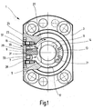
- the connection point 1 explained below comprises two tool parts, one of which is first in Top view is shown in Figure 1.
- the first Tool part 3 has a recess 5 into which a second tool part 7 can be inserted, the here indicated by a dashed circular line 9 is.
- the second tool part 7 has a hollow shaft on, which is inserted into the recess 5 is so that the collet 11 inside the Hollow shaft is arranged and this during manufacture junction 1, i.e. when bracing of the two tool parts 3 and 7 in the recess 5 by tightening it radially.
- the hollow shaft of the second tool part 7 has two extending in the longitudinal direction of the tool part 7 Slits in the one hand a head start 13 and on the other hand a device 15 for effecting intervene at a defined angle of rotation.
- the protrusion 13 arises from the inner surface 17 the recess 5 in the first tool part 3. It is dimensioned so that it fits in the hollow shaft of the second tool part 7 predetermined slot practically completely filled out. So that the side surfaces 19 and 21 of the projection 13 as contact surfaces for the flanks of the slot in the hollow shaft serve the second tool part 7.
- the slot in the second tool part 7 is a second one Slot provided in which an elastic element 23 of the device 15 engages.
- the elastic element 23 is in a first area on the first Tool part 3 clamped firmly and protrudes with one second area 25 in the recess 5 so that this in the path of movement of the second tool part 7 is when it is inserted into the recess 5 becomes.
- the connection point 1 i.e. when inserting the second tool part 7 in the recess 5 of the first tool part 3
- the second area 25 of the elastic Elements 23 reversibly deflected what a Restoring force. This will make one here Clockwise force built up on the Hollow shaft of the second tool part 7 works what is indicated by an arrow 27.
- the elastic element 23 is in one from the outside introduced the wall of the first tool part 3 first groove 29 housed. Parallel to this runs a second groove 31 into which a counterpart 33 is inserted.
- FIG 2 shows the first tool part 3 in longitudinal section. Same parts explained with reference to Figure 1 have the same reference numbers provided, so far to the description Figure 1 is referenced.
- the longitudinal cut is placed so that the counterpart 33 can be seen in side view. It is in the second groove 31. This is behind the counterpart 33 elastic element 23 can be seen, the first area, which is covered by the counterpart 33, in the first groove 29 is arranged.
- the first, covert Area of the elastic member 23 is as provide the counterpart 33 with an outer contour, its circumferential surface in cross section from the circular shape differs. He is polygonal here. This polygonal contour is intended to ensure that the elastic element 23 in the first area against rotation in the wall of the first tool part 3 is held.
- the pentagonal contour of the counterpart here 33, which corresponds to that of the first area of the elastic element 23 matches, is from the Illustration shown in Figure 1.
- Figure 2 shows a clamping screw 41, the perpendicular to the extension of the counterpart 33 and of the first region 43 of the elastic element 23 runs and into the base body of the first tool part 3 intervenes and serves the first Area of the elastic element 23 and the counterpart 33 non-rotatably in the first tool part 3 tense.
- FIG. 2 shows that the second region 25 of the elastic element 23 in the recess 5 of the first tool part 3 so protrudes into the movement path of the second tool part 7 protrudes when its hollow shaft is inserted into the recess 5.
- Figure 2 shows that the elastic element 23 is designed as a torsion element and essentially has an L-shaped configuration. At the end of the longer leg of the elastic element 23 is the first area behind the counterpart 33 rotatably on the first tool part 3 is clamped. The shorter leg of the elastic element 23, ie the second area 25, protrudes freely movable into the recess 5, if necessary with the hollow shaft of the second tool part 7 cooperate.
- Figure 3 shows the first tool part 3 of the connection point 1 in side view. It is clear here the cover plate 35 can be seen by the screws 37 and 39, which are shown in Figure 1, held , also by two further screws 37 ' and 39 '.
- the elastic is dashed in Figure 3 Element 23 indicated that in the associated first Nut 29 is housed, also the counterpart 33, which is arranged in the second groove 31. It also becomes clear here that the counterpart is shorter than the elastic element 23 and itself only extends over an area that is also from the Tension screw 41 is detected. This urges the first region 43 of the elastic element 23 against the upper edge 45 of the first groove 29 and at the same time the counterpart 33 against the lower flank 47 the first groove 31.
- the second recess 51 serves to be elastic Element 23 to move and if necessary to move the first groove 29 into the second groove 31, the counterpart 33 also correspondingly in the opposite groove is shifted. It is thus possible by means of the elastic element 23 a defined angular position in a simple manner ensure regardless of whether the hollow shaft of the second. Tool part 7 to the upper Side surface 19 or the lower side surface 21 of the Projection 13 should strike.
- the device 15 to effect a defined angular position universal for a right and / or left stop be used.
- FIG. 4 shows a section along that in FIG. 2 drawn line IV-IV. Is clearly recognizable here the cover plate anchored to the first tool part 3 35, the first groove 29 and the second Grooves 31 and thus the first area 43 of the elastic element and the counterpart 33 against rotation holds.
- the clamping screw 41 recognizable, which ensures that the first area 43 held securely and against twisting is supported. Due to the special contour of the first area 43 and that of the counterpart 33, the here V-shaped from top to bottom Have run-on bevels, the conical pushes downward tapering head of the clamping screw 41 the first region 43 and the counterpart 33 apart, that a twist of the elastic element 23 is safely avoided.
- Figure 5 illustrates the mode of operation once again the device 15 within the connection point 1, which is only partially shown here schematically is.
- Figure 5 shows the connection point 1 in Top view, as is also the case in FIG. 1.
- the second region 25 of the elastic is clearly Element 23 recognizable, which in the recess 5 of the here only indicated first tool part 3 and in the movement path of the second tool part 7 protrudes, of which the hollow shaft 53 is indicated here. It it can be seen here that the hollow shaft 53 two in slots 55 and 57 extending in the longitudinal direction thereof having. The second protrudes into the first slot 55 Area 25 of the elastic element 23, in the the second slot 57 projects the projection 13, which was explained with reference to Figure 1.
- the second Area 25 of the elastic element has one here Starting slope 59, which has a side surface 61 of the first slot 55 cooperates so that on the hollow shaft 53 in the direction of the arrow 27 directed force works.
- the elastic Elements 23 for right and left stop of the hollow shaft 53 on the projection 13, the second area 25 at its free end with symmetrical chamfers be provided. It is also possible to provide a mirror-image element 23, if one is opposite to arrow 27 Bracing force should be applied.
- the two Tool parts have a defined angle of rotation position can now be in the area of the connection point 1 a bracing of the two tool parts be made in which the cartridge 11 on is activated in the usual way and the hollow shaft 53rd of the second tool part 7 so that it extends rests securely on the inner surface of the recess 5.
- junction 1 In operation of the junction 1 can Projection 13 high torques from the first tool part 3 on the second tool part 7 or vice versa be transmitted.
- the tool rotates in the area of junction 1 against the Clockwise ensures that even under Load no relative rotation between the first Given tool part 3 and the second tool part 7 is because of the device 15 a system the side surface 63 of the hollow shaft 53 on the side surface 19 of the projection 13 is guaranteed.
Landscapes
- Mechanical Engineering (AREA)
- Engineering & Computer Science (AREA)
- Clamps And Clips (AREA)
- Details Of Spanners, Wrenches, And Screw Drivers And Accessories (AREA)
- Jigs For Machine Tools (AREA)
- Springs (AREA)
- Slide Fasteners, Snap Fasteners, And Hook Fasteners (AREA)
- Pivots And Pivotal Connections (AREA)
- Dental Tools And Instruments Or Auxiliary Dental Instruments (AREA)
- Insertion Pins And Rivets (AREA)
- Gyroscopes (AREA)
- Led Devices (AREA)
- Harvester Elements (AREA)
Abstract
Description
- Figur 1
- Eine Draufsicht auf ein erstes Werkzeugteil einer Verbindungsstelle;
- Figur 2
- einen Längsschnitt des in Figur 1 dargestellten Werkzeugteils;
- Figur 3
- eine Seitenansicht des in Figur 1 dargestellten Werkzeugteils;
- Figur 4
- einen Längsschnitt entlang der Linie IV - IV durch das in Figur 2 dargestellte Werkzeug und
- Figur 5
- eine schematische Darstellung einer Draufsicht auf ein erstes und zweites Werkzeugteil einer Verbindungsstelle.
Claims (11)
- Verbindungsstelle zwischen zwei Werkzeugteilen mit einer ein elastisches Element umfassenden Vorrichtung zum Bewirken einer definierten Drehwinkellage zwischen den Werkzeugteilen, dadurch gekennzeichnet, dass das elastische Element (23) in einem ersten Bereich (43) an dem ersten Werkzeugteil (3) so eingespannt ist, dass ein zweiter Bereich (25) beim Verbinden der Werkzeugteile (3,7) in die Bewegungsbahn des zweiten Werkzeugteils (7) ragt, so dass er von diesem ausgelenkt und reversibel verformt wird.
- Verbindungsstelle nach Anspruch 1, dadurch gekennzeichnet, dass das elastische Element (23) als Torsionselement ausgebildet ist.
- Verbindungsstelle nach Anspruch 1 oder 2, dadurch gekennzeichnet, dass das elastische Element (23) L-förmig ausgebildet ist und einen in den Verbindungsbereich zwischen dem ersten und zweiten Werkzeugteil (3,7) ragenden Vorsprung (zweiter Bereich (25)) aufweist.
- Verbindungsstelle nach einem der vorhergehenden Ansprüche, dadurch gekennzeichnet, dass das elastische Element (23) in dem am ersten Werkzeugteil (3) festgespannten ersten Bereich (43) mindestens einen Abschnitt aufweist, dessen Umfangsfläche im Querschnitt von der Kreisform abweicht.
- Verbindungsstelle nach einem der vorhergehenden Ansprüche, dadurch gekennzeichnet, dass das elastische Element (23) im ersten Bereich (43) einen im Querschnitt mehreckigen Abschnitt aufweist.
- Verbindungsstelle nach einem der vorhergehenden Ansprüche, dadurch gekennzeichnet, dass das erste Werkzeugteil (3) einen Teil des zweiten Werkzeugteils (7) aufnehmenden Ausnehmung (5) aufweist.
- Verbindungsstelle nach einem der vorhergehenden Ansprüche, dadurch gekennzeichnet, dass das elastische Element (23) in die Wandung des ersten Werkzeugteils (3) einsetzbar ist.
- Verbindungsstelle nach einem der vorhergehenden Ansprüche, dadurch gekennzeichnet, dass der Vorsprung des elastischen Elements (23) in der Wandung des ersten Werkzeugteils (3) angeordnet ist und in das Innere der Ausnehmung (5) ragt.
- Verbindungsstelle nach einem der vorhergehenden Ansprüche, dadurch gekennzeichnet, dass in die Wandung des ersten Werkzeugteils (3) zwei Nuten (29,31) zur Aufnahme eines elastischen Elements (23) angeordnet sind.
- Verbindungsstelle nach einem der vorhergehenden Ansprüche, dadurch gekennzeichnet, dass zumindest die erste Nut (29) eine die Wandung des ersten Werkzeugteils (3) durchdringende Ausnehmung (49) schneidet.
- Verbindungsstelle nach einem der vorhergehenden Ansprüche, dadurch gekennzeichnet, dass in die Wandung des ersten Werkzeugteils (3) ein dem elastischen Element (23) zugeordneten Gegenstück (33) einsetzbar ist.
Applications Claiming Priority (2)
| Application Number | Priority Date | Filing Date | Title |
|---|---|---|---|
| DE10114746 | 2001-03-22 | ||
| DE10114746A DE10114746A1 (de) | 2001-03-22 | 2001-03-22 | Verbindungsstelle |
Publications (2)
| Publication Number | Publication Date |
|---|---|
| EP1243803A1 true EP1243803A1 (de) | 2002-09-25 |
| EP1243803B1 EP1243803B1 (de) | 2009-01-07 |
Family
ID=7679043
Family Applications (1)
| Application Number | Title | Priority Date | Filing Date |
|---|---|---|---|
| EP02004826A Expired - Lifetime EP1243803B1 (de) | 2001-03-22 | 2002-03-02 | Verbindungsstelle zwischen zwei Werkzeugteilen |
Country Status (6)
| Country | Link |
|---|---|
| US (1) | US6776553B2 (de) |
| EP (1) | EP1243803B1 (de) |
| JP (1) | JP4074112B2 (de) |
| AT (1) | ATE420300T1 (de) |
| BR (1) | BR0200880B1 (de) |
| DE (2) | DE10114746A1 (de) |
Families Citing this family (1)
| Publication number | Priority date | Publication date | Assignee | Title |
|---|---|---|---|---|
| DE102005049615A1 (de) * | 2005-05-25 | 2007-06-28 | MAPAL Fabrik für Präzisionswerkzeuge Dr. Kress KG | ZB-Klickraster |
Citations (3)
| Publication number | Priority date | Publication date | Assignee | Title |
|---|---|---|---|---|
| DE2856720A1 (de) * | 1978-06-15 | 1979-12-20 | Matsui Universal Joint Mfg | Kupplung |
| EP0753680A1 (de) * | 1995-07-14 | 1997-01-15 | MAPAL Fabrik für Präzisionswerkzeuge Dr. Kress KG | Verbindungsstelle |
| JP2001150269A (ja) * | 1999-11-29 | 2001-06-05 | Big Alpha Kk | 工具ホルダーにおける工具位置決め部材と工具ホルダー |
Family Cites Families (4)
| Publication number | Priority date | Publication date | Assignee | Title |
|---|---|---|---|---|
| JPS59214531A (ja) * | 1983-05-18 | 1984-12-04 | N T Tool Kk | 保持具 |
| JP3341961B2 (ja) * | 1994-02-28 | 2002-11-05 | 株式会社ユニシアジェックス | 軸継手構造 |
| US5807180A (en) * | 1997-08-28 | 1998-09-15 | Dana Corporation | Constant velocity universal joint shaft and inner race combination |
| DE29922642U1 (de) * | 1999-12-24 | 2000-02-24 | Röhm GmbH, 89567 Sontheim | Spannvorrichtung für einen Hohlschaft |
-
2001
- 2001-03-22 DE DE10114746A patent/DE10114746A1/de not_active Ceased
-
2002
- 2002-03-02 DE DE50213185T patent/DE50213185D1/de not_active Expired - Lifetime
- 2002-03-02 AT AT02004826T patent/ATE420300T1/de not_active IP Right Cessation
- 2002-03-02 EP EP02004826A patent/EP1243803B1/de not_active Expired - Lifetime
- 2002-03-18 US US10/100,447 patent/US6776553B2/en not_active Expired - Lifetime
- 2002-03-21 BR BRPI0200880-7A patent/BR0200880B1/pt not_active IP Right Cessation
- 2002-03-22 JP JP2002081125A patent/JP4074112B2/ja not_active Expired - Fee Related
Patent Citations (3)
| Publication number | Priority date | Publication date | Assignee | Title |
|---|---|---|---|---|
| DE2856720A1 (de) * | 1978-06-15 | 1979-12-20 | Matsui Universal Joint Mfg | Kupplung |
| EP0753680A1 (de) * | 1995-07-14 | 1997-01-15 | MAPAL Fabrik für Präzisionswerkzeuge Dr. Kress KG | Verbindungsstelle |
| JP2001150269A (ja) * | 1999-11-29 | 2001-06-05 | Big Alpha Kk | 工具ホルダーにおける工具位置決め部材と工具ホルダー |
Non-Patent Citations (1)
| Title |
|---|
| PATENT ABSTRACTS OF JAPAN vol. 2000, no. 23 10 February 2001 (2001-02-10) * |
Also Published As
| Publication number | Publication date |
|---|---|
| EP1243803B1 (de) | 2009-01-07 |
| ATE420300T1 (de) | 2009-01-15 |
| US20020152853A1 (en) | 2002-10-24 |
| US6776553B2 (en) | 2004-08-17 |
| BR0200880B1 (pt) | 2010-10-19 |
| JP4074112B2 (ja) | 2008-04-09 |
| DE10114746A1 (de) | 2002-10-24 |
| DE50213185D1 (de) | 2009-02-26 |
| JP2002346869A (ja) | 2002-12-04 |
| BR0200880A (pt) | 2003-03-11 |
Similar Documents
| Publication | Publication Date | Title |
|---|---|---|
| EP0625395B1 (de) | Bohrwerkzeug für metallische Werkstoffe | |
| EP0385280B1 (de) | Innendrehmeissel | |
| EP1868756B1 (de) | Werkzeugaufbau | |
| DE60132455T2 (de) | Drehendes werkzeug mit einem ersetzbaren schneideinsatz an einem ende | |
| DE2822548C2 (de) | Werkzeug, insbesondere Bergbaumeißel, mit einem Halteschaft zur Befestigung in einem Aufnahmeteil einer Maschine | |
| DE69928548T2 (de) | Bohrwerkzeugzusammenbau | |
| DE2500216B2 (de) | Werkzeug zum Ausschneiden von Scheiben aus Blech o.dgl | |
| DE2608809C3 (de) | Spitzbohrwerkzeug | |
| EP1213081A1 (de) | Werkzeug zur spanenden Feinbearbeitung von Werkstücken | |
| DE102008063127A1 (de) | Werkzeug mit einem lösbar gespannten Schneidkörper | |
| EP2125278B1 (de) | Stosswerkzeug, insbesondere nutstosswerkzeug | |
| EP0410104B1 (de) | Zerspanungswerkzeug | |
| EP1971455A1 (de) | Werkzeugsystem für spanabhebende bearbeitung | |
| DE69923362T2 (de) | Werkzeug zur spanabhebenden Bearbeitung | |
| EP2082820A2 (de) | Zerspanungswerkzeug | |
| EP1262266A1 (de) | Spannvorrichtung | |
| DE102008005789B3 (de) | Zerspanungswerkzeug | |
| DE102015119431B4 (de) | Lochsäge | |
| EP3914411A1 (de) | Maschinenwerkzeug | |
| DE2533495B2 (de) | Bohrstange | |
| EP0033086B1 (de) | Bohrwerkzeug mit einem Wendebohrmesser | |
| DE102008005788B3 (de) | Zerspanungswerkzeug | |
| EP1243803A1 (de) | Verbindungsstelle zwischen zwei Werkzeugteilen | |
| EP0776723A1 (de) | Rotierendes Schaftwerkzeug | |
| DE10308036B4 (de) | Kugelkopierfräser |
Legal Events
| Date | Code | Title | Description |
|---|---|---|---|
| PUAI | Public reference made under article 153(3) epc to a published international application that has entered the european phase |
Free format text: ORIGINAL CODE: 0009012 |
|
| AK | Designated contracting states |
Kind code of ref document: A1 Designated state(s): AT BE CH CY DE DK ES FI FR GB GR IE IT LI LU MC NL PT SE TR |
|
| AX | Request for extension of the european patent |
Free format text: AL;LT;LV;MK;RO;SI |
|
| RIN1 | Information on inventor provided before grant (corrected) |
Inventor name: DER ERFINDER HAT AUF SEINE NENNUNG VERZICHTET. |
|
| 17P | Request for examination filed |
Effective date: 20030325 |
|
| AKX | Designation fees paid |
Designated state(s): AT BE CH CY DE DK ES FI FR GB GR IE IT LI LU MC NL PT SE TR |
|
| 17Q | First examination report despatched |
Effective date: 20080110 |
|
| GRAP | Despatch of communication of intention to grant a patent |
Free format text: ORIGINAL CODE: EPIDOSNIGR1 |
|
| GRAS | Grant fee paid |
Free format text: ORIGINAL CODE: EPIDOSNIGR3 |
|
| GRAA | (expected) grant |
Free format text: ORIGINAL CODE: 0009210 |
|
| AK | Designated contracting states |
Kind code of ref document: B1 Designated state(s): AT BE CH CY DE DK ES FI FR GB GR IE IT LI LU MC NL PT SE TR |
|
| REG | Reference to a national code |
Ref country code: GB Ref legal event code: FG4D Free format text: NOT ENGLISH |
|
| REG | Reference to a national code |
Ref country code: CH Ref legal event code: EP |
|
| REG | Reference to a national code |
Ref country code: CH Ref legal event code: NV Representative=s name: TROESCH SCHEIDEGGER WERNER AG |
|
| REG | Reference to a national code |
Ref country code: IE Ref legal event code: FG4D Free format text: LANGUAGE OF EP DOCUMENT: GERMAN |
|
| REF | Corresponds to: |
Ref document number: 50213185 Country of ref document: DE Date of ref document: 20090226 Kind code of ref document: P |
|
| REG | Reference to a national code |
Ref country code: SE Ref legal event code: TRGR |
|
| PG25 | Lapsed in a contracting state [announced via postgrant information from national office to epo] |
Ref country code: NL Free format text: LAPSE BECAUSE OF FAILURE TO SUBMIT A TRANSLATION OF THE DESCRIPTION OR TO PAY THE FEE WITHIN THE PRESCRIBED TIME-LIMIT Effective date: 20090107 |
|
| NLV1 | Nl: lapsed or annulled due to failure to fulfill the requirements of art. 29p and 29m of the patents act | ||
| PG25 | Lapsed in a contracting state [announced via postgrant information from national office to epo] |
Ref country code: FI Free format text: LAPSE BECAUSE OF FAILURE TO SUBMIT A TRANSLATION OF THE DESCRIPTION OR TO PAY THE FEE WITHIN THE PRESCRIBED TIME-LIMIT Effective date: 20090107 Ref country code: ES Free format text: LAPSE BECAUSE OF FAILURE TO SUBMIT A TRANSLATION OF THE DESCRIPTION OR TO PAY THE FEE WITHIN THE PRESCRIBED TIME-LIMIT Effective date: 20090418 |
|
| REG | Reference to a national code |
Ref country code: IE Ref legal event code: FD4D |
|
| PG25 | Lapsed in a contracting state [announced via postgrant information from national office to epo] |
Ref country code: PT Free format text: LAPSE BECAUSE OF FAILURE TO SUBMIT A TRANSLATION OF THE DESCRIPTION OR TO PAY THE FEE WITHIN THE PRESCRIBED TIME-LIMIT Effective date: 20090608 |
|
| BERE | Be: lapsed |
Owner name: MAPAL FABRIK FUR PRAZISIONSWERKZEUGE DR. KRESS K. Effective date: 20090331 |
|
| PG25 | Lapsed in a contracting state [announced via postgrant information from national office to epo] |
Ref country code: IE Free format text: LAPSE BECAUSE OF FAILURE TO SUBMIT A TRANSLATION OF THE DESCRIPTION OR TO PAY THE FEE WITHIN THE PRESCRIBED TIME-LIMIT Effective date: 20090107 Ref country code: DK Free format text: LAPSE BECAUSE OF FAILURE TO SUBMIT A TRANSLATION OF THE DESCRIPTION OR TO PAY THE FEE WITHIN THE PRESCRIBED TIME-LIMIT Effective date: 20090107 Ref country code: MC Free format text: LAPSE BECAUSE OF NON-PAYMENT OF DUE FEES Effective date: 20090331 |
|
| PLBE | No opposition filed within time limit |
Free format text: ORIGINAL CODE: 0009261 |
|
| STAA | Information on the status of an ep patent application or granted ep patent |
Free format text: STATUS: NO OPPOSITION FILED WITHIN TIME LIMIT |
|
| 26N | No opposition filed |
Effective date: 20091008 |
|
| PG25 | Lapsed in a contracting state [announced via postgrant information from national office to epo] |
Ref country code: BE Free format text: LAPSE BECAUSE OF NON-PAYMENT OF DUE FEES Effective date: 20090331 |
|
| PG25 | Lapsed in a contracting state [announced via postgrant information from national office to epo] |
Ref country code: AT Free format text: LAPSE BECAUSE OF NON-PAYMENT OF DUE FEES Effective date: 20090302 |
|
| PG25 | Lapsed in a contracting state [announced via postgrant information from national office to epo] |
Ref country code: LU Free format text: LAPSE BECAUSE OF NON-PAYMENT OF DUE FEES Effective date: 20090302 |
|
| PG25 | Lapsed in a contracting state [announced via postgrant information from national office to epo] |
Ref country code: TR Free format text: LAPSE BECAUSE OF FAILURE TO SUBMIT A TRANSLATION OF THE DESCRIPTION OR TO PAY THE FEE WITHIN THE PRESCRIBED TIME-LIMIT Effective date: 20090107 |
|
| PG25 | Lapsed in a contracting state [announced via postgrant information from national office to epo] |
Ref country code: CY Free format text: LAPSE BECAUSE OF FAILURE TO SUBMIT A TRANSLATION OF THE DESCRIPTION OR TO PAY THE FEE WITHIN THE PRESCRIBED TIME-LIMIT Effective date: 20090107 |
|
| PG25 | Lapsed in a contracting state [announced via postgrant information from national office to epo] |
Ref country code: GR Free format text: LAPSE BECAUSE OF FAILURE TO SUBMIT A TRANSLATION OF THE DESCRIPTION OR TO PAY THE FEE WITHIN THE PRESCRIBED TIME-LIMIT Effective date: 20090107 |
|
| REG | Reference to a national code |
Ref country code: FR Ref legal event code: PLFP Year of fee payment: 14 |
|
| PGFP | Annual fee paid to national office [announced via postgrant information from national office to epo] |
Ref country code: CH Payment date: 20150319 Year of fee payment: 14 |
|
| PGFP | Annual fee paid to national office [announced via postgrant information from national office to epo] |
Ref country code: FR Payment date: 20150319 Year of fee payment: 14 Ref country code: GB Payment date: 20150319 Year of fee payment: 14 Ref country code: SE Payment date: 20150319 Year of fee payment: 14 |
|
| PGFP | Annual fee paid to national office [announced via postgrant information from national office to epo] |
Ref country code: IT Payment date: 20150326 Year of fee payment: 14 |
|
| PGFP | Annual fee paid to national office [announced via postgrant information from national office to epo] |
Ref country code: DE Payment date: 20160324 Year of fee payment: 15 |
|
| REG | Reference to a national code |
Ref country code: CH Ref legal event code: PL |
|
| REG | Reference to a national code |
Ref country code: SE Ref legal event code: EUG |
|
| GBPC | Gb: european patent ceased through non-payment of renewal fee |
Effective date: 20160302 |
|
| PG25 | Lapsed in a contracting state [announced via postgrant information from national office to epo] |
Ref country code: SE Free format text: LAPSE BECAUSE OF NON-PAYMENT OF DUE FEES Effective date: 20160303 |
|
| REG | Reference to a national code |
Ref country code: FR Ref legal event code: ST Effective date: 20161130 |
|
| PG25 | Lapsed in a contracting state [announced via postgrant information from national office to epo] |
Ref country code: GB Free format text: LAPSE BECAUSE OF NON-PAYMENT OF DUE FEES Effective date: 20160302 Ref country code: LI Free format text: LAPSE BECAUSE OF NON-PAYMENT OF DUE FEES Effective date: 20160331 Ref country code: FR Free format text: LAPSE BECAUSE OF NON-PAYMENT OF DUE FEES Effective date: 20160331 Ref country code: CH Free format text: LAPSE BECAUSE OF NON-PAYMENT OF DUE FEES Effective date: 20160331 |
|
| PG25 | Lapsed in a contracting state [announced via postgrant information from national office to epo] |
Ref country code: IT Free format text: LAPSE BECAUSE OF NON-PAYMENT OF DUE FEES Effective date: 20160302 |
|
| REG | Reference to a national code |
Ref country code: DE Ref legal event code: R119 Ref document number: 50213185 Country of ref document: DE |
|
| PG25 | Lapsed in a contracting state [announced via postgrant information from national office to epo] |
Ref country code: DE Free format text: LAPSE BECAUSE OF NON-PAYMENT OF DUE FEES Effective date: 20171003 |