EP1241038B1 - Elément d'entraînement tel qu'une roue motrice ou un treuil de levage, comportant un moteur synchrone - Google Patents
Elément d'entraînement tel qu'une roue motrice ou un treuil de levage, comportant un moteur synchrone Download PDFInfo
- Publication number
- EP1241038B1 EP1241038B1 EP02290382A EP02290382A EP1241038B1 EP 1241038 B1 EP1241038 B1 EP 1241038B1 EP 02290382 A EP02290382 A EP 02290382A EP 02290382 A EP02290382 A EP 02290382A EP 1241038 B1 EP1241038 B1 EP 1241038B1
- Authority
- EP
- European Patent Office
- Prior art keywords
- fact
- drive element
- wheel
- element according
- rotor
- Prior art date
- Legal status (The legal status is an assumption and is not a legal conclusion. Google has not performed a legal analysis and makes no representation as to the accuracy of the status listed.)
- Expired - Lifetime
Links
Images
Classifications
-
- H—ELECTRICITY
- H02—GENERATION; CONVERSION OR DISTRIBUTION OF ELECTRIC POWER
- H02K—DYNAMO-ELECTRIC MACHINES
- H02K29/00—Motors or generators having non-mechanical commutating devices, e.g. discharge tubes or semiconductor devices
- H02K29/06—Motors or generators having non-mechanical commutating devices, e.g. discharge tubes or semiconductor devices with position sensing devices
- H02K29/08—Motors or generators having non-mechanical commutating devices, e.g. discharge tubes or semiconductor devices with position sensing devices using magnetic effect devices, e.g. Hall-plates, magneto-resistors
-
- B—PERFORMING OPERATIONS; TRANSPORTING
- B60—VEHICLES IN GENERAL
- B60K—ARRANGEMENT OR MOUNTING OF PROPULSION UNITS OR OF TRANSMISSIONS IN VEHICLES; ARRANGEMENT OR MOUNTING OF PLURAL DIVERSE PRIME-MOVERS IN VEHICLES; AUXILIARY DRIVES FOR VEHICLES; INSTRUMENTATION OR DASHBOARDS FOR VEHICLES; ARRANGEMENTS IN CONNECTION WITH COOLING, AIR INTAKE, GAS EXHAUST OR FUEL SUPPLY OF PROPULSION UNITS IN VEHICLES
- B60K7/00—Disposition of motor in, or adjacent to, traction wheel
- B60K7/0007—Disposition of motor in, or adjacent to, traction wheel the motor being electric
-
- B—PERFORMING OPERATIONS; TRANSPORTING
- B66—HOISTING; LIFTING; HAULING
- B66D—CAPSTANS; WINCHES; TACKLES, e.g. PULLEY BLOCKS; HOISTS
- B66D1/00—Rope, cable, or chain winding mechanisms; Capstans
- B66D1/02—Driving gear
- B66D1/12—Driving gear incorporating electric motors
-
- H—ELECTRICITY
- H02—GENERATION; CONVERSION OR DISTRIBUTION OF ELECTRIC POWER
- H02K—DYNAMO-ELECTRIC MACHINES
- H02K1/00—Details of the magnetic circuit
- H02K1/06—Details of the magnetic circuit characterised by the shape, form or construction
- H02K1/12—Stationary parts of the magnetic circuit
- H02K1/18—Means for mounting or fastening magnetic stationary parts on to, or to, the stator structures
- H02K1/185—Means for mounting or fastening magnetic stationary parts on to, or to, the stator structures to outer stators
-
- H—ELECTRICITY
- H02—GENERATION; CONVERSION OR DISTRIBUTION OF ELECTRIC POWER
- H02K—DYNAMO-ELECTRIC MACHINES
- H02K1/00—Details of the magnetic circuit
- H02K1/06—Details of the magnetic circuit characterised by the shape, form or construction
- H02K1/22—Rotating parts of the magnetic circuit
- H02K1/27—Rotor cores with permanent magnets
- H02K1/2706—Inner rotors
- H02K1/272—Inner rotors the magnetisation axis of the magnets being perpendicular to the rotor axis
- H02K1/274—Inner rotors the magnetisation axis of the magnets being perpendicular to the rotor axis the rotor consisting of two or more circumferentially positioned magnets
- H02K1/2753—Inner rotors the magnetisation axis of the magnets being perpendicular to the rotor axis the rotor consisting of two or more circumferentially positioned magnets the rotor consisting of magnets or groups of magnets arranged with alternating polarity
- H02K1/276—Magnets embedded in the magnetic core, e.g. interior permanent magnets [IPM]
- H02K1/2766—Magnets embedded in the magnetic core, e.g. interior permanent magnets [IPM] having a flux concentration effect
- H02K1/2773—Magnets embedded in the magnetic core, e.g. interior permanent magnets [IPM] having a flux concentration effect consisting of tangentially magnetized radial magnets
-
- H—ELECTRICITY
- H02—GENERATION; CONVERSION OR DISTRIBUTION OF ELECTRIC POWER
- H02K—DYNAMO-ELECTRIC MACHINES
- H02K11/00—Structural association of dynamo-electric machines with electric components or with devices for shielding, monitoring or protection
- H02K11/20—Structural association of dynamo-electric machines with electric components or with devices for shielding, monitoring or protection for measuring, monitoring, testing, protecting or switching
- H02K11/25—Devices for sensing temperature, or actuated thereby
-
- H—ELECTRICITY
- H02—GENERATION; CONVERSION OR DISTRIBUTION OF ELECTRIC POWER
- H02K—DYNAMO-ELECTRIC MACHINES
- H02K21/00—Synchronous motors having permanent magnets; Synchronous generators having permanent magnets
- H02K21/12—Synchronous motors having permanent magnets; Synchronous generators having permanent magnets with stationary armatures and rotating magnets
- H02K21/14—Synchronous motors having permanent magnets; Synchronous generators having permanent magnets with stationary armatures and rotating magnets with magnets rotating within the armatures
- H02K21/16—Synchronous motors having permanent magnets; Synchronous generators having permanent magnets with stationary armatures and rotating magnets with magnets rotating within the armatures having annular armature cores with salient poles
-
- H—ELECTRICITY
- H02—GENERATION; CONVERSION OR DISTRIBUTION OF ELECTRIC POWER
- H02K—DYNAMO-ELECTRIC MACHINES
- H02K21/00—Synchronous motors having permanent magnets; Synchronous generators having permanent magnets
- H02K21/12—Synchronous motors having permanent magnets; Synchronous generators having permanent magnets with stationary armatures and rotating magnets
- H02K21/22—Synchronous motors having permanent magnets; Synchronous generators having permanent magnets with stationary armatures and rotating magnets with magnets rotating around the armatures, e.g. flywheel magnetos
-
- H—ELECTRICITY
- H02—GENERATION; CONVERSION OR DISTRIBUTION OF ELECTRIC POWER
- H02K—DYNAMO-ELECTRIC MACHINES
- H02K3/00—Details of windings
- H02K3/04—Windings characterised by the conductor shape, form or construction, e.g. with bar conductors
- H02K3/18—Windings for salient poles
-
- H—ELECTRICITY
- H02—GENERATION; CONVERSION OR DISTRIBUTION OF ELECTRIC POWER
- H02K—DYNAMO-ELECTRIC MACHINES
- H02K3/00—Details of windings
- H02K3/46—Fastening of windings on the stator or rotor structure
- H02K3/52—Fastening salient pole windings or connections thereto
- H02K3/521—Fastening salient pole windings or connections thereto applicable to stators only
- H02K3/522—Fastening salient pole windings or connections thereto applicable to stators only for generally annular cores with salient poles
-
- H—ELECTRICITY
- H02—GENERATION; CONVERSION OR DISTRIBUTION OF ELECTRIC POWER
- H02K—DYNAMO-ELECTRIC MACHINES
- H02K5/00—Casings; Enclosures; Supports
- H02K5/04—Casings or enclosures characterised by the shape, form or construction thereof
- H02K5/16—Means for supporting bearings, e.g. insulating supports or means for fitting bearings in the bearing-shields
- H02K5/173—Means for supporting bearings, e.g. insulating supports or means for fitting bearings in the bearing-shields using bearings with rolling contact, e.g. ball bearings
- H02K5/1732—Means for supporting bearings, e.g. insulating supports or means for fitting bearings in the bearing-shields using bearings with rolling contact, e.g. ball bearings radially supporting the rotary shaft at both ends of the rotor
-
- H—ELECTRICITY
- H02—GENERATION; CONVERSION OR DISTRIBUTION OF ELECTRIC POWER
- H02K—DYNAMO-ELECTRIC MACHINES
- H02K7/00—Arrangements for handling mechanical energy structurally associated with dynamo-electric machines, e.g. structural association with mechanical driving motors or auxiliary dynamo-electric machines
- H02K7/10—Structural association with clutches, brakes, gears, pulleys or mechanical starters
-
- H—ELECTRICITY
- H02—GENERATION; CONVERSION OR DISTRIBUTION OF ELECTRIC POWER
- H02K—DYNAMO-ELECTRIC MACHINES
- H02K7/00—Arrangements for handling mechanical energy structurally associated with dynamo-electric machines, e.g. structural association with mechanical driving motors or auxiliary dynamo-electric machines
- H02K7/10—Structural association with clutches, brakes, gears, pulleys or mechanical starters
- H02K7/102—Structural association with clutches, brakes, gears, pulleys or mechanical starters with friction brakes
- H02K7/1021—Magnetically influenced friction brakes
-
- H—ELECTRICITY
- H02—GENERATION; CONVERSION OR DISTRIBUTION OF ELECTRIC POWER
- H02K—DYNAMO-ELECTRIC MACHINES
- H02K7/00—Arrangements for handling mechanical energy structurally associated with dynamo-electric machines, e.g. structural association with mechanical driving motors or auxiliary dynamo-electric machines
- H02K7/10—Structural association with clutches, brakes, gears, pulleys or mechanical starters
- H02K7/116—Structural association with clutches, brakes, gears, pulleys or mechanical starters with gears
-
- B—PERFORMING OPERATIONS; TRANSPORTING
- B60—VEHICLES IN GENERAL
- B60K—ARRANGEMENT OR MOUNTING OF PROPULSION UNITS OR OF TRANSMISSIONS IN VEHICLES; ARRANGEMENT OR MOUNTING OF PLURAL DIVERSE PRIME-MOVERS IN VEHICLES; AUXILIARY DRIVES FOR VEHICLES; INSTRUMENTATION OR DASHBOARDS FOR VEHICLES; ARRANGEMENTS IN CONNECTION WITH COOLING, AIR INTAKE, GAS EXHAUST OR FUEL SUPPLY OF PROPULSION UNITS IN VEHICLES
- B60K17/00—Arrangement or mounting of transmissions in vehicles
- B60K17/04—Arrangement or mounting of transmissions in vehicles characterised by arrangement, location or kind of gearing
- B60K17/043—Transmission unit disposed in on near the vehicle wheel, or between the differential gear unit and the wheel
- B60K17/046—Transmission unit disposed in on near the vehicle wheel, or between the differential gear unit and the wheel with planetary gearing having orbital motion
-
- B—PERFORMING OPERATIONS; TRANSPORTING
- B60—VEHICLES IN GENERAL
- B60K—ARRANGEMENT OR MOUNTING OF PROPULSION UNITS OR OF TRANSMISSIONS IN VEHICLES; ARRANGEMENT OR MOUNTING OF PLURAL DIVERSE PRIME-MOVERS IN VEHICLES; AUXILIARY DRIVES FOR VEHICLES; INSTRUMENTATION OR DASHBOARDS FOR VEHICLES; ARRANGEMENTS IN CONNECTION WITH COOLING, AIR INTAKE, GAS EXHAUST OR FUEL SUPPLY OF PROPULSION UNITS IN VEHICLES
- B60K7/00—Disposition of motor in, or adjacent to, traction wheel
- B60K2007/0046—Disposition of motor in, or adjacent to, traction wheel the motor moving together with the vehicle body, i.e. moving independently from the wheel axle
-
- B—PERFORMING OPERATIONS; TRANSPORTING
- B60—VEHICLES IN GENERAL
- B60K—ARRANGEMENT OR MOUNTING OF PROPULSION UNITS OR OF TRANSMISSIONS IN VEHICLES; ARRANGEMENT OR MOUNTING OF PLURAL DIVERSE PRIME-MOVERS IN VEHICLES; AUXILIARY DRIVES FOR VEHICLES; INSTRUMENTATION OR DASHBOARDS FOR VEHICLES; ARRANGEMENTS IN CONNECTION WITH COOLING, AIR INTAKE, GAS EXHAUST OR FUEL SUPPLY OF PROPULSION UNITS IN VEHICLES
- B60K7/00—Disposition of motor in, or adjacent to, traction wheel
- B60K2007/0092—Disposition of motor in, or adjacent to, traction wheel the motor axle being coaxial to the wheel axle
-
- B—PERFORMING OPERATIONS; TRANSPORTING
- B60—VEHICLES IN GENERAL
- B60L—PROPULSION OF ELECTRICALLY-PROPELLED VEHICLES; SUPPLYING ELECTRIC POWER FOR AUXILIARY EQUIPMENT OF ELECTRICALLY-PROPELLED VEHICLES; ELECTRODYNAMIC BRAKE SYSTEMS FOR VEHICLES IN GENERAL; MAGNETIC SUSPENSION OR LEVITATION FOR VEHICLES; MONITORING OPERATING VARIABLES OF ELECTRICALLY-PROPELLED VEHICLES; ELECTRIC SAFETY DEVICES FOR ELECTRICALLY-PROPELLED VEHICLES
- B60L2220/00—Electrical machine types; Structures or applications thereof
- B60L2220/10—Electrical machine types
- B60L2220/14—Synchronous machines
-
- B—PERFORMING OPERATIONS; TRANSPORTING
- B60—VEHICLES IN GENERAL
- B60L—PROPULSION OF ELECTRICALLY-PROPELLED VEHICLES; SUPPLYING ELECTRIC POWER FOR AUXILIARY EQUIPMENT OF ELECTRICALLY-PROPELLED VEHICLES; ELECTRODYNAMIC BRAKE SYSTEMS FOR VEHICLES IN GENERAL; MAGNETIC SUSPENSION OR LEVITATION FOR VEHICLES; MONITORING OPERATING VARIABLES OF ELECTRICALLY-PROPELLED VEHICLES; ELECTRIC SAFETY DEVICES FOR ELECTRICALLY-PROPELLED VEHICLES
- B60L2220/00—Electrical machine types; Structures or applications thereof
- B60L2220/50—Structural details of electrical machines
-
- B—PERFORMING OPERATIONS; TRANSPORTING
- B60—VEHICLES IN GENERAL
- B60Y—INDEXING SCHEME RELATING TO ASPECTS CROSS-CUTTING VEHICLE TECHNOLOGY
- B60Y2200/00—Type of vehicle
- B60Y2200/10—Road Vehicles
- B60Y2200/15—Fork lift trucks, Industrial trucks
-
- B—PERFORMING OPERATIONS; TRANSPORTING
- B62—LAND VEHICLES FOR TRAVELLING OTHERWISE THAN ON RAILS
- B62B—HAND-PROPELLED VEHICLES, e.g. HAND CARTS OR PERAMBULATORS; SLEDGES
- B62B5/00—Accessories or details specially adapted for hand carts
- B62B5/0026—Propulsion aids
- B62B5/0033—Electric motors
- B62B5/0036—Arrangements of motors
- B62B5/004—Arrangements of motors in wheels
-
- H—ELECTRICITY
- H02—GENERATION; CONVERSION OR DISTRIBUTION OF ELECTRIC POWER
- H02K—DYNAMO-ELECTRIC MACHINES
- H02K1/00—Details of the magnetic circuit
- H02K1/06—Details of the magnetic circuit characterised by the shape, form or construction
- H02K1/12—Stationary parts of the magnetic circuit
- H02K1/14—Stator cores with salient poles
- H02K1/146—Stator cores with salient poles consisting of a generally annular yoke with salient poles
-
- H—ELECTRICITY
- H02—GENERATION; CONVERSION OR DISTRIBUTION OF ELECTRIC POWER
- H02K—DYNAMO-ELECTRIC MACHINES
- H02K11/00—Structural association of dynamo-electric machines with electric components or with devices for shielding, monitoring or protection
-
- H—ELECTRICITY
- H02—GENERATION; CONVERSION OR DISTRIBUTION OF ELECTRIC POWER
- H02K—DYNAMO-ELECTRIC MACHINES
- H02K2203/00—Specific aspects not provided for in the other groups of this subclass relating to the windings
- H02K2203/06—Machines characterised by the wiring leads, i.e. conducting wires for connecting the winding terminations
-
- Y—GENERAL TAGGING OF NEW TECHNOLOGICAL DEVELOPMENTS; GENERAL TAGGING OF CROSS-SECTIONAL TECHNOLOGIES SPANNING OVER SEVERAL SECTIONS OF THE IPC; TECHNICAL SUBJECTS COVERED BY FORMER USPC CROSS-REFERENCE ART COLLECTIONS [XRACs] AND DIGESTS
- Y02—TECHNOLOGIES OR APPLICATIONS FOR MITIGATION OR ADAPTATION AGAINST CLIMATE CHANGE
- Y02T—CLIMATE CHANGE MITIGATION TECHNOLOGIES RELATED TO TRANSPORTATION
- Y02T10/00—Road transport of goods or passengers
- Y02T10/60—Other road transportation technologies with climate change mitigation effect
- Y02T10/64—Electric machine technologies in electromobility
Definitions
- the present invention relates to a drive element such as a drive wheel for industrial trucks, including pallet trucks or the like, or such as a hoist winch.
- this drive wheel is directional, being rotatable about a vertical axis.
- the diameter of gyration of the wheel must be as small as possible, in particular when the driving wheel is not central, in particular to allow to distance as far as possible the distance between the wheels of the carriage and to increase its stability.
- the wheel is rotated through a gearbox by an electric motor of DC or asynchronous type, which because of its size must be arranged above the wheel if the we want to meet the requirements of car manufacturers.
- Patent application EP-A-1 001 507 discloses an electric machine intended to be installed in a passenger vehicle wheel, comprising a rotor with flux concentration with permanent magnets.
- Patent application DE 197 32 637 discloses a drive wheel comprising an asynchronous motor and a squirrel cage rotor.
- the patent application EP-0 999 081 discloses a drive unit comprising an asynchronous motor.
- US Pat. No. 5,633,544 discloses a driving element according to the preamble of claim 1, in particular a drive wheel comprising a stator whose teeth comprise polar expansions, and a rotor comprising surface magnets.
- the object of the present invention is to propose a new drive element such as a drive wheel or a hoist winch, having a small footprint and a relatively simple structure.
- the rotor is at flux concentration, that is to say that the magnets are arranged between pole pieces.
- the combination of a flux-concentrating rotor and a stator wound on teeth makes it possible to have a relatively powerful machine with a small footprint, which notably allows the cantilever motor to be mounted at the end of the engine. a tree, resulting in a decrease in the number of bearings.
- the rotor can rotate at a high speed because the magnets are protected from the pulsating flow by the pole pieces. It is therefore not necessary to use fragmented magnets at high speeds, as is the case with the rotors whose magnets are mounted on the surface.
- the rotor magnets advantageously have a wedge shape when the machine is observed along the axis of rotation of the rotor, of decreasing width away from the axis of rotation of the rotor, and the pole pieces have cutouts and are engaged by these last on ribs of the tree. They are therefore fixed on the rotor shaft by complementarity of shapes.
- the cooperation between the wedge-shaped magnets on the one hand and the polar parts connected to the shaft by complementary shapes on the other hand is particularly advantageous in that the magnets can, at high speeds, exert on the pole pieces compression forces that tend to oppose the separation of the regions of the pole pieces located on either side of the ribs on which they are engaged. It thus becomes possible to avoid having to engage the pole pieces on bars, unlike what is described in US Patent 5,091,668.
- the fact of arranging the magnets between polar parts can protect them from the currents induced at high rotational speeds, and thus to avoid heating that may demagnetize them.
- the motor which is of reduced axial size can be placed inside a wheel, a drum or a pulley, the axis of the rotor being preferably coincident with the axis of rotation of the wheel, drum or pulley.
- the motor does not have to be offset upwards and the height of the drive wheel height is reduced, which allows car manufacturers to have additional space beyond above it.
- the invention also makes it possible to simplify the structure of the gearbox which may be used, which may comprise a single reduction stage, and may for example be an epicyclic gear train.
- the reduction factor may be less than fifteen, be between 7 and 12 for example, through the use of a permanent magnet rotor and a stator wound on teeth, which can work in attraction and repulsion, therefore to generate a larger torque than a reluctance motor that works only in attraction.
- the stator teeth can advantageously receive individual coils having very short heads, which allows to obtain a reduced axial size.
- the stator teeth are preferably free of polar expansion, which facilitates the introduction of the coils on the teeth and their removal, if necessary, to make a replacement.
- stator wound on teeth is still interesting in that it allows to realize the motor with a relatively small number of teeth and coils, so at an advantageous cost.
- the mass of the magnets used can also be relatively low, which makes it possible to reduce the material cost.
- the drive element comprises a main housing having a tubular wall of large diameter, a tubular wall of small diameter coaxial with the previous one and a transverse wall connecting said tubular walls.
- the stator is housed in the tubular wall of large diameter and the latter is secured to a first bearing part.
- the tubular wall of small diameter is secured to a second bearing part.
- the tubular walls of large and small diameters and the transverse wall are made in one piece.
- the tubular wall of large diameter may be constituted by an insert, the tubular wall of small diameter and the transverse wall being made in one piece.
- the second bearing part also constitutes a planet carrier and comprises at least one axis on which at least one satellite pinion rotates, preferably three satellite gears, each meshing pinion gear on the one hand with a pinion cut or attached to the rotor shaft and on the other hand with a crown of a support.
- This crown can be attached to the support or be made in one piece with him.
- a rim supporting the tire of the wheel can be fixed on this support.
- the drive element comprises a bearing allowing the support to rotate on the tubular wall of small diameter of the main casing.
- the drive element comprises a cover sealingly attached to the support.
- This cover can be used to contain a grease or lubricating oil of the reducer.
- the driving element comprises an electromagnetic brake with no current attached to the first bearing part, this brake comprising a disc fixed on a fluted end of the rotor shaft.
- the main housing may be rotatable or alternatively may be directly attached to the chassis when the drive member is a drive wheel and the wheel need not be a driver.
- the invention allows the rotor to be coaxial with the tire of the wheel or drum and thus reduce the vertical size of the drive element, the motor does not have to be deported.
- the invention also relates to a carriage equipped with at least one drive wheel as defined above, director or not.
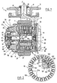
- FIG. 1 shows a drive wheel 1 according to an embodiment of the invention.
- This driving wheel 1 comprises an electric motor 2, which is, according to the invention, of the synchronous type, comprising a rotor 6 with permanent magnets, with flux concentration, and a stator 10 wound on teeth, the latter being represented at the figure 2.
- an electric motor 2 which is, according to the invention, of the synchronous type, comprising a rotor 6 with permanent magnets, with flux concentration, and a stator 10 wound on teeth, the latter being represented at the figure 2.
- Each tooth 10a carries an individual winding 10b of its own.
- the stator 10 comprises in the example described eighteen teeth, the rotor being twelve poles and the three-phase power supply.
- Each tooth 10a is devoid of polar expansion, as can be seen in FIG.
- Each tooth may comprise notches for mounting a shim, not shown, for holding the individual coils.
- the rotor 6 comprises permanent magnets 100, of transverse magnetization, arranged between polar pieces 102 each constituted by a stack of magnetic sheets, identical in shape and superimposed.
- the magnets 100 each have, when observed along the axis of rotation of the rotor, a generally wedge-shaped, of substantially trapezoidal cross-section, of decreasing width in approaching the stator. These magnets 100 are arranged radially between the pole pieces 102. The latter are not connected to each other magnetically, being fixed on a nonmagnetic shaft 101 by complementarity of shapes.
- the shaft has axial ribs 103 and the pole pieces 104 have correspondingly shaped cuts.
- the wedge shape of the magnets 100 allows efficient and simple maintenance on the rotor.
- Fixing the pole pieces by complementarity of shapes on the shaft makes it possible to make the connection between the shaft and the pole pieces so as to authorize the use, for making the shaft, of a non-magnetic material such as the aluminum.
- a non-magnetic material such as the aluminum.
- Other materials may be used, such as an aluminum alloy or a non-magnetic cast iron.
- Each individual coil 10b is formed by winding around a geometrical winding axis of electrical wires which may have a rectangular cross-section, of large side parallel to the winding axis. Alternatively, circular section wires may be used.
- the coils 10b are excited to produce a rotating field to drive the rotor.
- the drive wheel comprises a main casing 3 which is rotatably mounted on an element 5 integral with the frame of the carriage via a hollow shaft 12 and a bearing 4, so as to be able to rotate about an axis Z - Z 'vertical.
- the main casing 3 is fixed non-rotatably on the vehicle frame, the wheel is not a director.
- the main casing 3 comprises a tubular wall 7 of large diameter and a tubular wall 8 of small diameter, joined by a transverse wall 9.
- these three walls are made in one piece, but alternatively it could be different.
- the stator 10 of the motor is housed in the tubular wall 7 of large diameter, the transverse wall 9 having an annular groove 11 for accommodating the projecting portion of the stator windings.
- the shaft 13 of the rotor has a fluted end 14 and an end 15 provided with a cut pinion and a cylindrical axis end 16 of revolution.
- this pinion could be attached to the shaft.
- the tubular wall of large diameter 7 is fixed to an end piece or bearing flange 18, supporting a bearing 19 inside which rotates the fluted end portion 14.
- the small diameter tubular wall 8 of the main casing 3 is fixed to the planet carrier 20 by means of screws 41 and coupled to the planet carrier 20 by any appropriate means, for example pins 22.
- the coupling between the wall tubular 8 and planet carrier 20 can be done by complementarity of shapes, making teeth at the end of the tubular wall and a complementary shaped housing on the planet carrier.
- the planet carrier 20 carries a bearing 41 inside which rotates the axle end 16 of the rotor.
- the planet carrier supports axes 24 parallel to the axis X - X 'of rotation of the rotor, on each of which rotates a planet pinion 25.
- the wheel comprises three planet gears 25, which meshes with the pinion 15 cut on the rotor shaft 13 and with a ring 27a belonging to a support 27.
- 27a crown could, alternatively, be constituted by an insert.
- a bearing 28 is disposed between the tubular wall 8 of small diameter and the support 27, to allow the latter to rotate about the axis X - X '.
- a rim 30 carrying a tire 31 is fixed on the support 27 by means of screw 32.
- a cover 33 is sealingly attached to the support 27.
- the support 27 has at its periphery a cylindrical surface of revolution in which is formed an annular groove housing an O-ring 34, against which the cover 33 is applied.
- the seal could be obtained differently.
- the wheel 1 comprises, on the opposite side to the planetary gear reducer which has just been described, a brake 36 with no current, fixed on the piece 18 serving as a bearing.
- This brake comprises a disc 37 provided with a splined hub 38 which engages on the grooved end 14 of the rotor, and brake linings, in a manner known per se.
- the brake also comprises a moving element 40 which is able to be applied against the disc 37 in the absence of power supply to the motor.
- the power supply and control cables 45 of the electric motor extend inside the hollow shaft 12 hinged to the frame. Alternatively, the output of the cables can be done differently.
- the drive wheel 1 which has just been described has an axial size less than the outer diameter of the tire new or adjacent thereto, which makes it possible to meet the requirements of the car manufacturers.
- the motor is housed inside the wheel, without being deported above the tire, which allows for additional space on the carriage.
- the main casing can be fixed non-rotatably on the chassis of the trolley.
- braking can be done otherwise, using the engine for example.
- the reducer can of course be modified and can in particular change the number of satellite gears.
- the invention also applies to a hoist winch, in which the engine drives a winch or pulley.
Landscapes
- Engineering & Computer Science (AREA)
- Power Engineering (AREA)
- Mechanical Engineering (AREA)
- Microelectronics & Electronic Packaging (AREA)
- Transportation (AREA)
- Combustion & Propulsion (AREA)
- Chemical & Material Sciences (AREA)
- Arrangement Or Mounting Of Propulsion Units For Vehicles (AREA)
- Connection Of Motors, Electrical Generators, Mechanical Devices, And The Like (AREA)
- Retarders (AREA)
- Permanent Magnet Type Synchronous Machine (AREA)
- Control And Safety Of Cranes (AREA)
- Control Of Electric Motors In General (AREA)
Description
- La présente invention concerne un élément d'entraînement tel qu'une roue motrice pour chariots de manutention, notamment transpalettes ou analogues, ou tel qu'un treuil de levage.
- Parmi les différents modes de motorisation des chariots de manutention, la roue motrice est le plus répandu.
- Dans la majorité des cas, cette roue motrice est directionnelle, étant mobile en rotation autour d'un axe vertical.
- Le diamètre de giration de la roue doit être le plus réduit possible, en particulier lorsque la roue motrice n'est pas centrale, afin notamment de permettre d'écarter au maximum la distance entre les roues du chariot et d'accroître sa stabilité.
- Les constructeurs de chariots imposent fréquemment que le diamètre de giration soit celui du pneumatique de la roue.
- Dans les roues motrices connues, la roue est entraînée en rotation au travers d'un réducteur par un moteur électrique de type à courant continu ou de type asynchrone, qui du fait de son encombrement doit être disposé au-dessus de la roue si l'on veut satisfaire aux exigences des constructeurs de chariots.
- Il en résulte un encombrement vertical assez important et une structure relativement complexe.
- Un problème d'encombrement similaire se pose pour les treuils de levage, dont le moteur entraîne un tambour.
- On connaît par la demande de brevet EP-A-1 001 507 une machine électrique destinée à être implantée dans une roue de véhicule de tourisme, comportant un rotor à concentration de flux à aimants permanents.
- On connaît par la demande de brevet EP-A2-1 187 302 opposable au titre de l'article 54(3) CBE, un moteur comportant un rotor à aimant permanent, les pôles nord et sud de ces aimants étant placés alternativement face au stator et le stator comportant des pôles principaux comportant chacun à leur extrémité face au rotor des dents.
- On connaît par la demande de brevet DE 197 32 637 une roue motrice comportant un moteur asynchrone et un rotor à cage d'écureuil.
- On connaît par la demande de brevet EP-0 999 081 une unité motrice comportant un moteur asynchrone.
- On connaît par le brevet US 5 633 544 un élément d'entraînement selon le préambule de la revendication 1, notamment une roue motrice comportant un stator dont les dents comportent des épanouissements polaires, et un rotor comportant des aimants en surface.
- La présente invention a pour objet de proposer un nouvel élément d'entraînement tel qu'une roue motrice ou un treuil de levage, présentant un encombrement réduit et une structure relativement simple.
- Ce nouvel élément d'entraînement est décrit dans la revendication 1.
- Par stator bobiné sur dents, on entend un stator dont chaque dent porte un bobinage qui lui est propre, à la différence des stators dont les enroulements sont enchevêtrés et qui présentent l'inconvénient d'avoir un encombrement axial plus important en raison de la longueur relativement grande des têtes de chignons, due au mode de bobinage. De plus, le nombre de dents ndents est de préférence fonction du nombre de paires de pôles npaires et du nombre de phases nphases suivant la formule ndents = npaires * nphases.
- Se préférence le rotor est à concentration de flux, c'est-à-dire que les aimants sont disposés entre des pièces polaires. La combinaison d'un rotor à concentration de flux et d'un stator bobiné sur dents permet d'avoir une machine relativement puissante sous un faible encombrement, ce qui autorise notamment le montage du moteur en porte-à-faux à l'extrémité d'un arbre, entraînant une diminution du nombre de roulements. Le rotor peut tourner à une vitesse élevée, car les aimants sont protégés du flux pulsant par les pièces polaires. Il n'est donc pas nécessaire d'utiliser des aimants fragmentés aux grandes vitesses, comme c'est le cas avec les rotors dont les aimants sont montés en surface.
- Les aimants du rotor présentent avantageusement une forme de coin lorsque la machine est observée selon l'axe de rotation du rotor, de largeur diminuant en éloignement de l'axe de rotation du rotor, et les pièces polaires présentent des découpes et sont engagées par ces dernières sur des nervures de l'arbre. Elles sont donc fixées sur l'arbre du rotor par complémentarité de formes. La coopération entre d'une part les aimants en forme de coin et d'autre part les pièces polaires reliées à l'arbre par complémentarité de formes est particulièrement avantageuse en ce que les aimants peuvent, aux vitesses élevées, exercer sur les pièces polaires des forces de compression qui tendent à s'opposer à l'écartement des régions des pièces polaires situées de part et d'autre des nervures sur lesquelles elles sont engagées. Il devient ainsi possible d'éviter d'avoir à engager les pièces polaires sur des barreaux, à la différence de ce qui est décrit dans le brevet US 5 091 668.
- De plus, le fait de disposer les aimants entre des pièces polaires permet de les protéger des courants induits aux grandes vitesses de rotation, et donc d'éviter un échauffement susceptible de les démagnétiser.
- Dans l'invention, le moteur qui est d'encombrement axial réduit peut être placé à l'intérieur d'une roue, d'un tambour ou d'une poulie, l'axe du rotor étant de préférence confondu avec l'axe de rotation de la roue, du tambour ou de la poulie. Dans le cas d'une roue motrice, le moteur n'a pas à être déporté vers le haut et l'encombrement de la roue motrice en hauteur est réduit, ce qui permet aux constructeurs de chariots de disposer d'un espace supplémentaire au-dessus de celle-ci.
- L'invention permet également de simplifier la structure du réducteur éventuellement utilisé, lequel peut comporter un étage de réduction unique, et être à train épicycloïdal par exemple.
- Le facteur de réduction peut être inférieur à quinze, être compris entre 7 et 12 par exemple, grâce à l'utilisation d'un rotor à aimants permanents et d'un stator bobiné sur dents, qui permettent de travailler en attraction et en répulsion, donc de générer un couple plus important qu'un moteur à réluctance qui ne travaille qu'en attraction.
- Les dents du stator peuvent avantageusement recevoir des bobines individuelles présentant des têtes très courtes, ce qui permet d'obtenir un encombrement axial réduit. Les dents du stator sont alors de préférence dépourvues d'épanouissement polaires, ce qui facilite la mise en place des bobines sur les dents et leur enlèvement, en cas de besoin, pour procéder à un remplacement.
- L'utilisation d'un stator bobiné sur dents est encore intéressante en ce qu'elle permet de réaliser le moteur avec un nombre relativement faible de dents et de bobines, donc à un coût avantageux. La masse des aimants utilisés peut également être relativement peu élevée, ce qui permet de diminuer le coût matière.
- Selon l'invention, l'élément d'entraînement comporte un carter principal ayant une paroi tubulaire de grand diamètre, une paroi tubulaire de petit diamètre coaxiale à la précédente et une paroi transversale reliant lesdites parois tubulaires. Le stator est logé dans la paroi tubulaire de grand diamètre et cette dernière est solidaire d'une première pièce formant palier. La paroi tubulaire de petit diamètre est solidaire d'une deuxième pièce formant palier. De préférence, les parois tubulaires de grand et petit diamètres et la paroi transversale sont réalisées d'un seul tenant. En variante, la paroi tubulaire de grand diamètre peut être constituée par une pièce rapportée, la paroi tubulaire de petit diamètre et la paroi transversale étant réalisées d'un seul tenant.
- La deuxième pièce formant palier constitue également un porte-satellites et comporte au moins un axe sur lequel tourne au moins un pignon satellite, de préférence trois pignons satellites, chaque pignon satellite engrenant d'une part avec un pignon taillé ou rapporté sur l'arbre du rotor et d'autre part avec une couronne d'un support. Cette couronne peut être rapportée sur le support ou être réalisée d'un seul tenant avec lui. Dans le cas d'une roue motrice, une jante supportant le pneumatique de la roue peut être fixée sur ce support.
- Dans une réalisation particulière, l'élément d'entraînement comporte un roulement permettant au support de tourner sur la paroi tubulaire de petit diamètre du carter principal.
- Toujours dans une réalisation particulière, l'élément d'entraînement comporte un capot rapporté de manière étanche sur le support. Ce capot peut servir à contenir une graisse ou huile de lubrification du réducteur.
- De préférence, dans le cas d'une roue motrice ou d'un treuil, l'élément d'entraînement comporte un frein électromagnétique à manque de courant rapporté sur la première pièce formant palier, ce frein comportant un disque fixé sur une extrémité cannelée de l'arbre du rotor. Le carter principal peut être rotatif ou en variante être fixé directement sur le châssis, lorsque l'élément d'entraînement est une roue motrice et que la roue n'a pas à être directrice.
- Comme expliqué plus haut, l'invention permet au rotor d'être coaxial au pneumatique de la roue ou au tambour et donc de réduire l'encombrement vertical de l'élément d'entraînement, le moteur n'ayant pas à être déporté.
- L'invention a encore pour objet un chariot équipé d'au moins une roue motrice telle que définie plus haut, directrice ou non.
- L'invention sera mieux comprise à la lecture de la description détaillée qui va suivre et à l'examen du dessin annexé, sur lequel :
- la figure 1 est une vue schématique en coupe axiale d'une roue motrice conforme à un exemple de réalisation, non limitatif, et
- la figure 2 représente isolément et schématiquement, en section transversale, le stator bobiné sur dents et, partiellement, le rotor.
- On a représenté sur la figure 1 une roue motrice 1 conforme à un exemple de mise en oeuvre de l'invention.
- Cette roue motrice 1 comporte un moteur électrique 2, qui est, conformément à l'invention, du type synchrone, comportant un rotor 6 à aimants permanents, à concentration de flux, et un stator 10 bobiné sur dents, ce dernier étant représenté à la figure 2.
- Chaque dent 10a porte un bobinage individuel 10b qui lui est propre. Le stator 10 comporte dans l'exemple décrit dix-huit dents, le rotor étant à douze pôles et le courant d'alimentation triphasé.
- Chaque dent 10a est dépourvue d'épanouissement polaire, comme on peut le voir sur la figure 2.
- Chaque dent peut comporter des encoches pour le montage d'une cale, non représentée, de maintien des bobines individuelles.
- Le rotor 6 comporte des aimants permanents 100, d'aimantation transverse, disposés entre des pièces polaires 102 constituées chacune par un paquet de tôles magnétiques, de forme identique et superposées.
- Les aimants 100 présentent chacun, lorsque observés selon l'axe de rotation du rotor, une forme générale en coin, de section transversale sensiblement trapézoïdale, de largeur diminuant en rapprochement du stator. Ces aimants 100 sont disposés radialement entre les pièces polaires 102. Ces dernières ne sont pas reliées entre elles magnétiquement, étant fixées sur un arbre amagnétique 101 par complémentarité de formes. L'arbre présente à cet effet des nervures axiales 103 et les pièces polaires des découpes 104 de forme correspondante. La forme en coin des aimants 100 permet un maintien efficace et simple sur le rotor. La fixation des pièces polaires par complémentarité de formes sur l'arbre permet de réaliser la liaison entre l'arbre et les pièces polaires de manière à autoriser l'emploi, pour fabriquer l'arbre, d'une matière amagnétique telle que de l'aluminium. D'autres matières peuvent être utilisées, comme par exemple un alliage d'aluminium ou une fonte amagnétique.
- Chaque bobine individuelle 10b est formée par l'enroulement autour d'un axe géométrique d'enroulement de fils électriques qui peuvent présenter une section transversale rectangulaire, de grand côté parallèle à l'axe d'enroulement. En variante, des fils de section circulaire peuvent être utilisés.
- Les bobines 10b sont excitées de manière à produire un champ tournant, afin d'entraîner le rotor.
- La roue motrice comporte un carter principal 3 qui est monté rotatif sur un élément 5 solidaire du châssis du chariot par l'intermédiaire d'un axe creux 12 et d'un roulement 4, de manière à pouvoir tourner autour d'un d'axe Z - Z' vertical.
- Dans une variante non illustrée, le carter principal 3 est fixé de manière non rotative sur le châssis du véhicule, la roue n'étant pas directrice.
- Le carter principal 3 comporte une paroi tubulaire 7 de grand diamètre et une paroi tubulaire 8 de petit diamètre, réunies par une paroi transversale 9.
- Dans l'exemple illustré, ces trois parois sont réalisées d'un seul tenant, mais en variante il pourrait en être différemment.
- Le stator 10 du moteur est logé dans la paroi tubulaire 7 de grand diamètre, la paroi transversale 9 présentant une gorge annulaire 11 permettant de loger la partie en saillie des enroulements du stator.
- L'arbre 13 du rotor comporte une extrémité 14 cannelée et une extrémité 15 pourvue d'un pignon taillé et d'un bout d'axe 16 cylindrique de révolution. En variante, ce pignon pourrait être rapporté sur l'arbre.
- La paroi tubulaire de grand diamètre 7 est fixée à une pièce d'extrémité ou flasque formant palier 18, supportant un roulement 19 à l'intérieur duquel tourne la partie d'extrémité cannelée 14.
- La paroi tubulaire 8 de petit diamètre du carter principal 3 est fixée au porte-satellites 20 au moyen de vis 41 et accouplée au porte-satellites 20 par tout moyen approprié, par exemple des goupilles 22. En variante, l'accouplement entre la paroi tubulaire 8 et le porte-satellites 20 peut se faire par complémentarité de formes, en réalisant des dents à l'extrémité de la paroi tubulaire et un logement de forme complémentaire sur le porte-satellites.
- Le porte-satellites 20 porte un roulement 41 à l'intérieur duquel tourne le bout d'axe 16 du rotor.
- Le porte-satellites supporte des axes 24 parallèles à l'axe X - X' de rotation du rotor, sur chacun desquels tourne un pignon satellite 25.
- Dans l'exemple de réalisation décrit, la roue comporte trois pignons satellites 25, qui engrènent d'une part avec le pignon 15 taillé sur l'arbre 13 du rotor et d'autre part avec une couronne 27a appartenant à un support 27. La couronne 27a pourrait, en variante, être constituée par un élément rapporté.
- Un roulement 28 est disposé entre la paroi tubulaire 8 de petit diamètre et le support 27, pour permettre à ce dernier de tourner autour de l'axe X - X'.
- Une jante 30 portant un pneumatique 31 est fixée sur le support 27 au moyen de vis 32.
- Un capot 33 est fixé de manière étanche sur le support 27.
- Dans l'exemple de réalisation décrit, le support 27 présente à sa périphérie une surface cylindrique de révolution dans laquelle est réalisée une gorge annulaire logeant un joint torique 34, contre lequel vient s'appliquer le capot 33. L'étanchéité pourrait être obtenue différemment.
- La roue 1 comporte, du côté opposé au réducteur à train épicycloïdal qui vient d'être décrit, un frein 36 à manque de courant, fixé sur la pièce 18 servant de palier.
- Ce frein comporte un disque 37 pourvu d'un moyeu cannelé 38 qui vient en prise sur l'extrémité cannelée 14 du rotor, et de garnitures de freinage, de manière connue en soi.
- Le frein comporte également un équipage mobile 40 qui est apte à s'appliquer contre le disque 37 en l'absence d'alimentation du moteur.
- Les câbles 45 d'alimentation et de contrôle du moteur électrique s'étendent à l'intérieur de l'axe creux 12 articulé sur le châssis. En variante, la sortie des câbles peut se faire autrement.
- La roue motrice 1 qui vient d'être décrite présente un encombrement axial inférieur au diamètre extérieur du pneumatique neuf ou voisin de celui-ci, ce qui permet de satisfaire aux exigences des constructeurs de chariots.
- Le moteur est logé à l'intérieur de la roue, sans être déporté au-dessus du pneumatique, ce qui permet de disposer d'un espace supplémentaire sur le chariot.
- Bien entendu, l'invention n'est pas limitée à l'exemple de réalisation qui vient d'être décrit.
- En particulier, comme indiqué plus haut, le carter principal peut être fixé non rotatif sur le châssis du chariot.
- On peut également ne pas utiliser de réducteur, auquel cas le moteur entraîne directement la roue.
- On peut encore ne pas utiliser de frein, le freinage pouvant être effectué autrement, à l'aide du moteur par exemple.
- Le réducteur peut bien entendu être modifié et l'on peut notamment changer le nombre de pignons satellites.
- L'invention s'applique également à un treuil de levage, dans lequel le moteur entraîne un treuil ou une poulie.
Claims (13)
- Elément d'entraînement tel qu'une roue motrice pour chariot de manutention ou analogue ou tel qu'un treuil de levage, comportant une roue ou un tambour et un moteur électrique pour entraîner la roue ou le tambour en rotation, le moteur électrique étant un moteur synchrone comprenant un rotor (6) à aimants permanents (100) et un stator comportant un carter principal (3) comportant une paroi tubulaire (7) de grand diamètre et une paroi tubulaire (8) de petit diamètre reliées par une paroi transversale (9), le stator (10) étant logé dans la paroi tubulaire (7) de grand diamètre, cette dernière étant solidaire d'une première pièce formant palier (18), la paroi tubulaire de petit diamètre étant solidaire d'une deuxième pièce (20) formant palier, caractérisé par le fait que le stator est bobiné sur dents et par le fait que la deuxième pièce formant palier constitue également un porte-satellites et comporte au moins un axe (24) sur lequel tourne au moins un pignon satellite (25), de préférence trois pignons satellites, chaque pignon satellite (25) engrenant avec un pignon (15) taillé ou rapporté sur l'arbre du rotor et avec une couronne d'un support (27).
- Elément d'entraînement selon la revendication 1, caractérisé par le fait que le rotor (6) est à concentration de flux et comporte des aimants (100) disposés entre des pièces polaires (102).
- Elément d'entraînement selon la revendication 1, ne comportant qu'un seul étage de réduction.
- Elément d'entraînement selon la revendication 3 le rapport de réduction étant inférieur ou égal à quinze, notamment compris entre 7 et 12.
- Elément d'entraînement selon l'une quelconque des revendications précédentes caractérisé par le fait qu'une jante (30) supportant un pneumatique (31) est fixée sur le support (27).
- Elément d'entraînement selon l'une quelconque des revendications précédentes caractérisé par le fait que le support (27) tourne par l'intermédiaire d'un roulement sur la paroi tubulaire (8) de petit diamètre du carter principal (3).
- Elément d'entraînement selon l'une des revendications précédentes, caractérisé par le fait qu'il comporte un capot (33) rapporté de manière étanche sur le support (27).
- Elément d'entraînement selon l'une quelconque des revendications précédentes, caractérisé par le fait qu'il comporte un frein électromagnétique (36) à manque de courant, rapporté sur ladite première pièce (18) formant palier, ce frein comportant un disque (37) fixé sur une extrémité cannelée (14) de l'arbre du moteur.
- Elément d'entraînement selon l'une quelconque des revendications précédentes, caractérisé par le fait que le moteur entraîne une roue et par le fait que le carter principal (3) est rotatif autour d'un axe vertical (Z - Z').
- Elément d'entraînement selon l'une quelconque des revendications précédentes, caractérisé par le fait que le moteur entraîne une roue et par le fait que le carter principal est fixé non rotatif sur le châssis du chariot.
- Elément d'entraînement selon l'une quelconque des revendications précédentes, caractérisé par le fait que le moteur entraîne une roue et par le fait que le rotor est coaxial au pneumatique (31) de la roue
- Elément d'entraînement selon l'une quelconque des revendications précédentes, caractérisé par le fait que les dents du stator sont dépourvues d'épanouissements polaires.
- Chariot équipé d'un élément d'entraînement tel que défini dans l'une quelconque des revendications précédentes.
Applications Claiming Priority (4)
| Application Number | Priority Date | Filing Date | Title |
|---|---|---|---|
| FR0102263 | 2001-02-20 | ||
| FR0102263A FR2821023A1 (fr) | 2001-02-20 | 2001-02-20 | Roue motrice a moteur synchrone |
| FR0105412A FR2821024B1 (fr) | 2001-02-20 | 2001-04-20 | Element d'entrainement tel qu'une roue motrice ou un treuil de levage, comportant un moteur synchrone |
| FR0105412 | 2001-04-20 |
Publications (2)
| Publication Number | Publication Date |
|---|---|
| EP1241038A1 EP1241038A1 (fr) | 2002-09-18 |
| EP1241038B1 true EP1241038B1 (fr) | 2006-12-13 |
Family
ID=26212884
Family Applications (1)
| Application Number | Title | Priority Date | Filing Date |
|---|---|---|---|
| EP02290382A Expired - Lifetime EP1241038B1 (fr) | 2001-02-20 | 2002-02-18 | Elément d'entraînement tel qu'une roue motrice ou un treuil de levage, comportant un moteur synchrone |
Country Status (6)
| Country | Link |
|---|---|
| US (1) | US6661137B2 (fr) |
| EP (1) | EP1241038B1 (fr) |
| JP (1) | JP2002369448A (fr) |
| AT (1) | ATE348022T1 (fr) |
| DE (1) | DE60216652T2 (fr) |
| FR (1) | FR2821024B1 (fr) |
Families Citing this family (46)
| Publication number | Priority date | Publication date | Assignee | Title |
|---|---|---|---|---|
| US6891299B2 (en) * | 2000-05-03 | 2005-05-10 | Moteurs Leroy-Somer | Rotary electric machine having a flux-concentrating rotor and a stator with windings on teeth |
| US7814641B2 (en) | 2001-01-09 | 2010-10-19 | Black & Decker Inc. | Method of forming a power tool |
| US7096566B2 (en) | 2001-01-09 | 2006-08-29 | Black & Decker Inc. | Method for making an encapsulated coil structure |
| US6946758B2 (en) | 2001-01-09 | 2005-09-20 | Black & Decker Inc. | Dynamoelectric machine having encapsulated coil structure with one or more of phase change additives, insert molded features and insulated pinion |
| CN100511924C (zh) | 2001-01-09 | 2009-07-08 | 布莱克-德克尔公司 | 一种转子涂复导热塑料的电动机 |
| FR2823614B1 (fr) | 2001-04-17 | 2008-07-11 | Leroy Somer Moteurs | Machine tournante electrique comportant un stator forme de secteurs assembles |
| DE10260001A1 (de) * | 2002-12-20 | 2004-07-08 | Zf Friedrichshafen Ag | Axiale Sicherung der Radlagerung für deichselgeführte Fahrzeuge |
| DE10260003A1 (de) * | 2002-12-20 | 2004-07-08 | Zf Friedrichshafen Ag | Radnabenantrieb |
| TW595072B (en) * | 2003-01-06 | 2004-06-21 | Unique Product & Design Co Ltd | Assembly type rotor structure of brushless motor |
| FR2853156A1 (fr) * | 2003-03-31 | 2004-10-01 | Leroy Somer Moteurs | Machine electrique synchrone comportant un stator et au moins un rotor et dispositif de commande associe |
| FR2858723B1 (fr) * | 2003-08-08 | 2005-12-30 | Leroy Somer Moteurs | Machine electrique, notamment pour ascenseur |
| US7233091B2 (en) | 2003-09-05 | 2007-06-19 | Black & Decker Inc. | Electric motor with field assemblies having core pieces with mating features |
| US7211920B2 (en) | 2003-09-05 | 2007-05-01 | Black & Decker Inc. | Field assemblies having pole pieces with axial lengths less than an axial length of a back iron portion and methods of making same |
| US7205696B2 (en) | 2003-09-05 | 2007-04-17 | Black & Decker Inc. | Field assemblies having pole pieces with ends that decrease in width, and methods of making same |
| US7078843B2 (en) | 2003-09-05 | 2006-07-18 | Black & Decker Inc. | Field assemblies and methods of making same |
| EP2562912A1 (fr) | 2005-03-07 | 2013-02-27 | Black & Decker Inc. | Outils électriques avec moteur présentant un stator constitué de plusieurs pièces |
| TWI353705B (en) * | 2005-08-26 | 2011-12-01 | Hoeganaes Ab | An electric rotary machine |
| DE102005046616A1 (de) * | 2005-09-29 | 2007-04-19 | Zf Friedrichshafen Ag | Antriebseiheit |
| US7579738B2 (en) * | 2005-10-31 | 2009-08-25 | Greenee Energy Inc. | Multi-phase electrical motor for use in a wheel |
| FR2893460A1 (fr) * | 2005-11-14 | 2007-05-18 | Leroy Somer Moteurs | Machine electrique tournante. |
| DE102005058941A1 (de) * | 2005-12-09 | 2007-06-14 | Zf Friedrichshafen Ag | Anordnung der Elektronikkomponenten bzw. Elektronikbaugruppen bei einem Handhubwagen, umfassend einen Lenkmotor, ein Lenkgetriebe und einen lenkbaren Antrieb |
| NO324241B1 (no) * | 2006-02-28 | 2007-09-17 | Smartmotor As | Anordning ved elektrisk maskin |
| USD581952S1 (en) | 2006-08-11 | 2008-12-02 | Hall David R | Pick |
| ITVI20060035U1 (it) * | 2006-09-06 | 2008-03-07 | Amer Spa | Ruota motorizzata |
| DE202007005966U1 (de) | 2007-04-26 | 2007-06-28 | Jungheinrich Aktiengesellschaft | Kabelführung in einer Antriebseinheit eines deichselgelenkten Flurförderzeugs |
| FR2930483B1 (fr) * | 2008-04-29 | 2010-09-03 | Peugeot Citroen Automobiles Sa | Transmission comportant un treuil pour vehicule avec motorisation electrique |
| WO2010056385A1 (fr) | 2008-11-14 | 2010-05-20 | Williams Kevin R | Système de volant d’inertie pour une utilisation avec des roues électriques dans un véhicule hybride |
| US20100329905A1 (en) * | 2008-12-02 | 2010-12-30 | Williams Kevin R | Permanent magnet direct drive mud pump |
| US20110309315A1 (en) | 2008-12-22 | 2011-12-22 | Williams Kevin R | Two speed direct drive drawworks |
| US8672059B2 (en) * | 2008-12-22 | 2014-03-18 | Canrig Drilling Technology Ltd. | Permanent magnet direct drive drawworks |
| CA2778833C (fr) * | 2009-12-21 | 2018-03-06 | Kevin R. Williams | Treuils de forage a prise directe a aimant permanent |
| US9556008B2 (en) * | 2013-11-05 | 2017-01-31 | Everett Ogden | Winch with drum-encased brushless DC motor |
| CN106233581A (zh) | 2014-02-03 | 2016-12-14 | 坎里格钻探技术有限公司 | 电动机中永磁体的联接 |
| WO2015138833A1 (fr) | 2014-03-13 | 2015-09-17 | Canrig Drilling Technology Ltd. | Treuil de forage à entraînement direct à faible inertie |
| US9919903B2 (en) | 2014-03-13 | 2018-03-20 | Nabors Drilling Technologies Usa, Inc. | Multi-speed electric motor |
| US10150659B2 (en) | 2014-08-04 | 2018-12-11 | Nabors Drilling Technologies Usa, Inc. | Direct drive drawworks with bearingless motor |
| FR3029466B1 (fr) | 2014-12-03 | 2018-03-23 | Moteurs Leroy-Somer | Dispositif d'entrainement pour chariot ou analogue |
| US9634599B2 (en) | 2015-01-05 | 2017-04-25 | Canrig Drilling Technology Ltd. | High speed ratio permanent magnet motor |
| GB201504447D0 (en) * | 2015-03-17 | 2015-04-29 | Qinetiq Ltd | Electric hub drive with braking assembly |
| CN105946549B (zh) * | 2016-05-27 | 2018-03-23 | 浙江联宜电机有限公司 | 电动轮毂及驱动轮 |
| JP2018131068A (ja) * | 2017-02-15 | 2018-08-23 | ナブテスコ株式会社 | 運搬台車用の駆動装置 |
| CN108494159A (zh) * | 2018-04-18 | 2018-09-04 | 江苏磁谷科技股份有限公司 | 一种永磁直驱辊筒 |
| CN109256885A (zh) * | 2018-10-10 | 2019-01-22 | 常州工学院 | 一种使用寿命长的永磁电机 |
| CN109969226A (zh) * | 2019-03-28 | 2019-07-05 | 唐山百川智能机器股份有限公司 | 伸缩轮式动力单元和轨道行走式动车组底部检测装置 |
| DE102021117625A1 (de) | 2021-07-08 | 2023-01-12 | Knorr-Bremse Systeme für Nutzfahrzeuge GmbH | Permanenterregte Elektromaschine |
| DE202021103729U1 (de) * | 2021-07-12 | 2022-10-13 | Blickle Räder + Rollen GmbH u. Co. KG | Antriebsrad für einen Transportwagen, Antriebssystem mit einem solchen Antriebsrad und Transportwagen |
Citations (1)
| Publication number | Priority date | Publication date | Assignee | Title |
|---|---|---|---|---|
| EP1187302A2 (fr) * | 2000-07-28 | 2002-03-13 | Japan Servo Co. Ltd. | Système actionné par un moteur avec pôles statoriques dentés |
Family Cites Families (58)
| Publication number | Priority date | Publication date | Assignee | Title |
|---|---|---|---|---|
| US669699A (en) * | 1900-08-14 | 1901-03-12 | Don Jackson | Hame-hook. |
| US871758A (en) | 1906-10-18 | 1907-11-19 | Crocker Wheeler Co | Bridging-blocks for dynamo-electric machines. |
| US1045159A (en) | 1910-02-07 | 1912-11-26 | Robert Lundell | Interpole field-magnet. |
| GB258981A (en) | 1925-07-25 | 1926-10-07 | British Lighting And Ignition | Improvements in or relating to dynamo-electric machines |
| US2386673A (en) | 1944-06-10 | 1945-10-09 | Gen Electric | Winding slot wedge |
| US3889140A (en) | 1968-08-31 | 1975-06-10 | Max Baermann Fa | Induction brake or clutch |
| CN1172839C (zh) | 1997-03-18 | 2004-10-27 | 三菱电机株式会社 | 电梯用提升装置 |
| US4339874A (en) | 1978-12-26 | 1982-07-20 | The Garrett Corporation | Method of making a wedge-shaped permanent magnet rotor assembly |
| US4302693A (en) | 1978-12-26 | 1981-11-24 | The Garrett Corporation | Wedge shaped permanent magnet rotor assembly with magnet cushions |
| US4617725A (en) | 1984-10-01 | 1986-10-21 | Siemens-Allis, Inc. | Method of making multiple-element strap winding for rotor pole |
| JPH01278247A (ja) | 1988-04-30 | 1989-11-08 | Fanuc Ltd | 同期電動機 |
| DE3826933A1 (de) * | 1988-08-09 | 1990-02-15 | Kordel Getriebe Gmbh & Co Kg | Radnabengetriebe |
| JP2652048B2 (ja) | 1988-09-30 | 1997-09-10 | 日本電産株式会社 | モータ |
| FR2652688B2 (fr) | 1989-01-11 | 1991-10-18 | Alsthom Gec | Commande pour la marche a puissance constante d'un moto-variateur synchrone. |
| JPH0332333A (ja) | 1989-06-26 | 1991-02-12 | Fanuc Ltd | ラジアルタイプのロータ構造 |
| FR2655214B1 (fr) | 1989-11-27 | 1992-02-07 | Alsthom Gec | Rotor de moteur a aimants. |
| FR2655784B1 (fr) | 1989-12-08 | 1992-01-24 | Alsthom Gec | Moteur a aimants a concentration de flux. |
| IT1244276B (it) * | 1990-07-03 | 1994-07-08 | Elettromeccanica Parizzi Spa | Gruppo ruota-motore elettrico per carrelli di veicoli ferrotranviari |
| DE4218888C2 (de) * | 1992-06-09 | 1995-06-08 | Barth Hubert Dipl Ing Fh | Elektrische Maschine |
| CA2139584A1 (fr) | 1992-07-09 | 1994-01-20 | Takashi Nagate | Moteur sans balais |
| JP3430521B2 (ja) | 1992-09-24 | 2003-07-28 | 松下電器産業株式会社 | 回転電機の固定子 |
| US5693995A (en) | 1993-06-14 | 1997-12-02 | Ecoair Corp. | Hybrid alternator |
| US5691584A (en) * | 1993-09-09 | 1997-11-25 | Honda Giken Kogyo Kabushiki Kaisha | Wheel motor for vehicles |
| JP3369673B2 (ja) * | 1993-09-28 | 2003-01-20 | 本田技研工業株式会社 | ホイールモータ |
| JPH07107707A (ja) | 1993-10-04 | 1995-04-21 | Shibaura Eng Works Co Ltd | モータ |
| DE4406471C2 (de) | 1994-02-23 | 1998-04-09 | Mannesmann Sachs Ag | Rotierende elektrische Maschine mit Außenläufer |
| JPH07264822A (ja) | 1994-03-18 | 1995-10-13 | Hitachi Ltd | 多相多重化電動機 |
| FR2723272B1 (fr) | 1994-07-27 | 1996-08-30 | Gec Alsthom Parvex Sa | Moteur synchrone comportant des aimants inseres dans un rotor |
| FR2726948B1 (fr) | 1994-11-16 | 1996-12-20 | Wavre Nicolas | Moteur synchrone a aimants permanents |
| DE19503610C2 (de) | 1995-02-03 | 1997-05-22 | Zajc Franc | Mehrphasige und vielpolige, elektrisch kommutierbare Maschine und Verfahren zur Herstellung des Ständers |
| US5744888A (en) | 1995-02-03 | 1998-04-28 | Tiedtke-Buhling-Kinne & Partner | Multiphase and multipole electrical machine |
| US5747909A (en) | 1996-03-14 | 1998-05-05 | Ecoair Corp. | Hybrid alternator |
| JPH099602A (ja) | 1995-06-21 | 1997-01-10 | Toyoda Mach Works Ltd | ステッピングモータ |
| DE19544830A1 (de) | 1995-12-01 | 1997-06-05 | Mulfingen Elektrobau Ebm | Stator für Elektromotoren |
| JP3690616B2 (ja) | 1996-04-15 | 2005-08-31 | 日立金属株式会社 | 回転機 |
| JP2972907B2 (ja) | 1996-05-28 | 1999-11-08 | 日本サーボ株式会社 | 集中巻固定子を有する永久磁石回転電機 |
| JP3635814B2 (ja) | 1996-10-18 | 2005-04-06 | 株式会社日立製作所 | 集中巻回転電機 |
| JPH10146030A (ja) | 1996-11-05 | 1998-05-29 | Hitachi Ltd | 集中巻固定子を有する回転電機 |
| US5851162A (en) | 1996-11-19 | 1998-12-22 | Tether; David | System and apparatus for a multiple input and dual output electric differential motor transmission device |
| GB9701994D0 (en) * | 1997-01-31 | 1997-03-19 | Surgical Technology Uk Limited | Surgical fixation peg |
| US6025665A (en) | 1997-02-21 | 2000-02-15 | Emerson Electric Co. | Rotating machine for use in a pressurized fluid system |
| US5952755A (en) | 1997-03-18 | 1999-09-14 | Electric Boat Corporation | Permanent magnet motor rotor |
| TW380329B (en) * | 1997-04-16 | 2000-01-21 | Japan Servo | Permanent-magnet revolving electrodynamic machine with a concentrated winding stator |
| US5885091A (en) * | 1997-05-05 | 1999-03-23 | Ford Motor Company | Method and apparatus for providing planar and non-planar compliant electrical connections between adjacent circuits |
| DE19732637C5 (de) * | 1997-07-29 | 2006-09-14 | Daimlerchrysler Ag | Elektrischer Antrieb für eine Radnabe |
| JP4202446B2 (ja) * | 1997-09-14 | 2008-12-24 | 本田技研工業株式会社 | ハイブリッド型自動二輪車のパワーユニット配置構造 |
| JPH1198791A (ja) | 1997-09-16 | 1999-04-09 | Mitsubishi Heavy Ind Ltd | ブラシレスdcモータ |
| KR100263445B1 (ko) | 1997-11-13 | 2000-08-01 | 윤종용 | 브러시리스 dc모터용 회전자 |
| JP3442636B2 (ja) | 1998-01-06 | 2003-09-02 | オークマ株式会社 | 永久磁石電動機 |
| JP3601757B2 (ja) | 1998-08-03 | 2004-12-15 | オークマ株式会社 | 永久磁石モータ |
| FR2784815B1 (fr) | 1998-10-20 | 2001-06-08 | Valeo Equip Electr Moteur | Machine electrique tournante, en particulier alternateur de vehicule automobile, possedant des moyens perfectionnes de reduction de bruit |
| DE19851155A1 (de) * | 1998-11-06 | 2000-05-18 | Abm Greiffenberger Antriebstec | Antriebseinheit für ein elektrisch angetriebenes Fahrzeug |
| ES2257837T3 (es) | 1998-11-13 | 2006-08-01 | Conception Et Developpement Michelin | Maquina electrica cuyo rotor esta especialmente adaptado a las altas velocidades. |
| DE19920127C2 (de) | 1999-05-03 | 2001-05-31 | Mannesmann Sachs Ag | Stator für eine elektrische Maschine und Verfahren zur Herstellung eines Stators |
| JP2000333407A (ja) | 1999-05-18 | 2000-11-30 | Seiichi Tada | ホイールモーター |
| JP3787756B2 (ja) | 2000-08-29 | 2006-06-21 | 株式会社日立製作所 | 永久磁石式回転電機 |
| JP2002112476A (ja) | 2000-09-28 | 2002-04-12 | Hitachi Ltd | 永久磁石式回転電機 |
| FR2823612B1 (fr) | 2001-04-17 | 2003-06-13 | Leroy Somer Moteurs | Stator de machine tournante electrique comportant des bobines individuelles demontables |
-
2001
- 2001-04-20 FR FR0105412A patent/FR2821024B1/fr not_active Expired - Fee Related
-
2002
- 2002-02-15 US US10/075,450 patent/US6661137B2/en not_active Expired - Lifetime
- 2002-02-18 EP EP02290382A patent/EP1241038B1/fr not_active Expired - Lifetime
- 2002-02-18 DE DE60216652T patent/DE60216652T2/de not_active Expired - Lifetime
- 2002-02-18 AT AT02290382T patent/ATE348022T1/de not_active IP Right Cessation
- 2002-02-20 JP JP2002043995A patent/JP2002369448A/ja active Pending
Patent Citations (1)
| Publication number | Priority date | Publication date | Assignee | Title |
|---|---|---|---|---|
| EP1187302A2 (fr) * | 2000-07-28 | 2002-03-13 | Japan Servo Co. Ltd. | Système actionné par un moteur avec pôles statoriques dentés |
Also Published As
| Publication number | Publication date |
|---|---|
| ATE348022T1 (de) | 2007-01-15 |
| FR2821024B1 (fr) | 2003-06-13 |
| JP2002369448A (ja) | 2002-12-20 |
| DE60216652T2 (de) | 2007-09-27 |
| EP1241038A1 (fr) | 2002-09-18 |
| US6661137B2 (en) | 2003-12-09 |
| FR2821024A1 (fr) | 2002-08-23 |
| DE60216652D1 (de) | 2007-01-25 |
| US20020121823A1 (en) | 2002-09-05 |
Similar Documents
| Publication | Publication Date | Title |
|---|---|---|
| EP1241038A1 (fr) | Elément d'entrainement tel qu'une roue motrice ou un treuil de levage, compartant un moteur synchrone | |
| EP2279089B1 (fr) | Moyeu motorisé pour un véhicule automobile à traction électrique | |
| FR2935564A1 (fr) | Dispositif de montage d'un resolver dans une machine electrique | |
| EP1540177A2 (fr) | Dispositif d'entrainement pour une eolienne munie de deux helices contre rotatives | |
| FR2767425A1 (fr) | Entrainement electrique pour un moyeu de roue | |
| FR2500688A1 (fr) | Groupe electrique d'entrainement avec poulie supportee par le carter | |
| FR2962079A1 (fr) | Moyeu motorise comprenant une machine electrique de traction. | |
| FR2935561A1 (fr) | Flasque connecteur pour machine electrique a enroulements statoriques | |
| CH665316A5 (fr) | Ralentisseur electrique. | |
| EP2102965A1 (fr) | Machine electrique tournante, en particulier pour un demarreur de vehicule automobile | |
| EP1505030B1 (fr) | Machine électrique, notamment pour ascenseur | |
| EP3053262B1 (fr) | Machine electrique tournante polyphasee a au moins cinq phases | |
| FR2879043A1 (fr) | Essieu moteur equipe d'un moteur electrique et d'un differentiel integre pour un chariot transporteur | |
| CA2240865A1 (fr) | Systeme d'entrainement en rotation d'un dispositif | |
| EP2866344B1 (fr) | Machine électrique tournante polyphasée à au moins cinq phases à commande optimisée | |
| FR2859951A1 (fr) | Groupe d'entrainement pour un chariot transporteur notamment un chariot elevateur a timon | |
| FR2821023A1 (fr) | Roue motrice a moteur synchrone | |
| EP0789442B1 (fr) | Transmission de véhicule équipée d'un ralentisseur électrique | |
| FR2922060A1 (fr) | Machine electrique tournante comportant deux stators | |
| EP0789443A1 (fr) | Transmission de véhicule équipée d'un ralentisseur électrique | |
| FR2890342A1 (fr) | Systeme modulaire pour reducteurs a engrenage droit de puissances differentes pour chariots de manutention | |
| FR3124036A1 (fr) | Machine électrique tournante à flux axial multiple ayant une configuration creuse | |
| EP0789444B1 (fr) | Transmission de véhicule équipée d'un ralentisseur électrique | |
| WO2004091081A1 (fr) | Ralentisseur electromagnetique d’un vehicule comportant un alternateur | |
| EP1786086A2 (fr) | Ensemble d'une machine électrique tournante et d'un frein |
Legal Events
| Date | Code | Title | Description |
|---|---|---|---|
| PUAI | Public reference made under article 153(3) epc to a published international application that has entered the european phase |
Free format text: ORIGINAL CODE: 0009012 |
|
| AK | Designated contracting states |
Kind code of ref document: A1 Designated state(s): AT BE CH CY DE DK ES FI FR GB GR IE IT LI LU MC NL PT SE TR |
|
| AX | Request for extension of the european patent |
Free format text: AL;LT;LV;MK;RO;SI |
|
| 17P | Request for examination filed |
Effective date: 20021031 |
|
| AKX | Designation fees paid |
Designated state(s): AT BE CH CY DE DK ES FI FR GB GR IE IT LI LU MC NL PT SE TR |
|
| 17Q | First examination report despatched |
Effective date: 20030819 |
|
| GRAP | Despatch of communication of intention to grant a patent |
Free format text: ORIGINAL CODE: EPIDOSNIGR1 |
|
| GRAS | Grant fee paid |
Free format text: ORIGINAL CODE: EPIDOSNIGR3 |
|
| GRAA | (expected) grant |
Free format text: ORIGINAL CODE: 0009210 |
|
| AK | Designated contracting states |
Kind code of ref document: B1 Designated state(s): AT BE CH CY DE DK ES FI FR GB GR IE IT LI LU MC NL PT SE TR |
|
| PG25 | Lapsed in a contracting state [announced via postgrant information from national office to epo] |
Ref country code: NL Free format text: LAPSE BECAUSE OF FAILURE TO SUBMIT A TRANSLATION OF THE DESCRIPTION OR TO PAY THE FEE WITHIN THE PRESCRIBED TIME-LIMIT Effective date: 20061213 Ref country code: FI Free format text: LAPSE BECAUSE OF FAILURE TO SUBMIT A TRANSLATION OF THE DESCRIPTION OR TO PAY THE FEE WITHIN THE PRESCRIBED TIME-LIMIT Effective date: 20061213 Ref country code: AT Free format text: LAPSE BECAUSE OF FAILURE TO SUBMIT A TRANSLATION OF THE DESCRIPTION OR TO PAY THE FEE WITHIN THE PRESCRIBED TIME-LIMIT Effective date: 20061213 Ref country code: IE Free format text: LAPSE BECAUSE OF FAILURE TO SUBMIT A TRANSLATION OF THE DESCRIPTION OR TO PAY THE FEE WITHIN THE PRESCRIBED TIME-LIMIT Effective date: 20061213 Ref country code: DK Free format text: LAPSE BECAUSE OF FAILURE TO SUBMIT A TRANSLATION OF THE DESCRIPTION OR TO PAY THE FEE WITHIN THE PRESCRIBED TIME-LIMIT Effective date: 20061213 |
|
| REG | Reference to a national code |
Ref country code: GB Ref legal event code: FG4D Free format text: NOT ENGLISH |
|
| REG | Reference to a national code |
Ref country code: CH Ref legal event code: EP |
|
| REG | Reference to a national code |
Ref country code: IE Ref legal event code: FG4D Free format text: LANGUAGE OF EP DOCUMENT: FRENCH |
|
| REF | Corresponds to: |
Ref document number: 60216652 Country of ref document: DE Date of ref document: 20070125 Kind code of ref document: P |
|
| GBT | Gb: translation of ep patent filed (gb section 77(6)(a)/1977) |
Effective date: 20070207 |
|
| PG25 | Lapsed in a contracting state [announced via postgrant information from national office to epo] |
Ref country code: MC Free format text: LAPSE BECAUSE OF NON-PAYMENT OF DUE FEES Effective date: 20070228 Ref country code: LI Free format text: LAPSE BECAUSE OF NON-PAYMENT OF DUE FEES Effective date: 20070228 Ref country code: CH Free format text: LAPSE BECAUSE OF NON-PAYMENT OF DUE FEES Effective date: 20070228 |
|
| PG25 | Lapsed in a contracting state [announced via postgrant information from national office to epo] |
Ref country code: ES Free format text: LAPSE BECAUSE OF FAILURE TO SUBMIT A TRANSLATION OF THE DESCRIPTION OR TO PAY THE FEE WITHIN THE PRESCRIBED TIME-LIMIT Effective date: 20070324 |
|
| REG | Reference to a national code |
Ref country code: SE Ref legal event code: TRGR |
|
| PG25 | Lapsed in a contracting state [announced via postgrant information from national office to epo] |
Ref country code: PT Free format text: LAPSE BECAUSE OF FAILURE TO SUBMIT A TRANSLATION OF THE DESCRIPTION OR TO PAY THE FEE WITHIN THE PRESCRIBED TIME-LIMIT Effective date: 20070514 |
|
| NLV1 | Nl: lapsed or annulled due to failure to fulfill the requirements of art. 29p and 29m of the patents act | ||
| REG | Reference to a national code |
Ref country code: IE Ref legal event code: FD4D |
|
| REG | Reference to a national code |
Ref country code: CH Ref legal event code: PL |
|
| PLBE | No opposition filed within time limit |
Free format text: ORIGINAL CODE: 0009261 |
|
| STAA | Information on the status of an ep patent application or granted ep patent |
Free format text: STATUS: NO OPPOSITION FILED WITHIN TIME LIMIT |
|
| 26N | No opposition filed |
Effective date: 20070914 |
|
| BERE | Be: lapsed |
Owner name: MOTEURS LEROY-SOMER Effective date: 20070228 |
|
| PG25 | Lapsed in a contracting state [announced via postgrant information from national office to epo] |
Ref country code: BE Free format text: LAPSE BECAUSE OF NON-PAYMENT OF DUE FEES Effective date: 20070228 |
|
| PG25 | Lapsed in a contracting state [announced via postgrant information from national office to epo] |
Ref country code: GR Free format text: LAPSE BECAUSE OF FAILURE TO SUBMIT A TRANSLATION OF THE DESCRIPTION OR TO PAY THE FEE WITHIN THE PRESCRIBED TIME-LIMIT Effective date: 20070314 |
|
| PG25 | Lapsed in a contracting state [announced via postgrant information from national office to epo] |
Ref country code: LU Free format text: LAPSE BECAUSE OF NON-PAYMENT OF DUE FEES Effective date: 20070218 Ref country code: CY Free format text: LAPSE BECAUSE OF FAILURE TO SUBMIT A TRANSLATION OF THE DESCRIPTION OR TO PAY THE FEE WITHIN THE PRESCRIBED TIME-LIMIT Effective date: 20061213 |
|
| PG25 | Lapsed in a contracting state [announced via postgrant information from national office to epo] |
Ref country code: TR Free format text: LAPSE BECAUSE OF FAILURE TO SUBMIT A TRANSLATION OF THE DESCRIPTION OR TO PAY THE FEE WITHIN THE PRESCRIBED TIME-LIMIT Effective date: 20061213 |
|
| REG | Reference to a national code |
Ref country code: FR Ref legal event code: PLFP Year of fee payment: 15 |
|
| PGFP | Annual fee paid to national office [announced via postgrant information from national office to epo] |
Ref country code: IT Payment date: 20160225 Year of fee payment: 15 |
|
| PGFP | Annual fee paid to national office [announced via postgrant information from national office to epo] |
Ref country code: GB Payment date: 20160217 Year of fee payment: 15 Ref country code: SE Payment date: 20160222 Year of fee payment: 15 |
|
| PGFP | Annual fee paid to national office [announced via postgrant information from national office to epo] |
Ref country code: DE Payment date: 20160418 Year of fee payment: 15 |
|
| REG | Reference to a national code |
Ref country code: FR Ref legal event code: PLFP Year of fee payment: 16 |
|
| PGFP | Annual fee paid to national office [announced via postgrant information from national office to epo] |
Ref country code: FR Payment date: 20170131 Year of fee payment: 16 |
|
| REG | Reference to a national code |
Ref country code: DE Ref legal event code: R119 Ref document number: 60216652 Country of ref document: DE |
|
| REG | Reference to a national code |
Ref country code: SE Ref legal event code: EUG |
|
| GBPC | Gb: european patent ceased through non-payment of renewal fee |
Effective date: 20170218 |
|
| PG25 | Lapsed in a contracting state [announced via postgrant information from national office to epo] |
Ref country code: SE Free format text: LAPSE BECAUSE OF NON-PAYMENT OF DUE FEES Effective date: 20170219 |
|
| PG25 | Lapsed in a contracting state [announced via postgrant information from national office to epo] |
Ref country code: DE Free format text: LAPSE BECAUSE OF NON-PAYMENT OF DUE FEES Effective date: 20170901 |
|
| PG25 | Lapsed in a contracting state [announced via postgrant information from national office to epo] |
Ref country code: IT Free format text: LAPSE BECAUSE OF NON-PAYMENT OF DUE FEES Effective date: 20170218 Ref country code: GB Free format text: LAPSE BECAUSE OF NON-PAYMENT OF DUE FEES Effective date: 20170218 |
|
| REG | Reference to a national code |
Ref country code: FR Ref legal event code: ST Effective date: 20181031 |
|
| PG25 | Lapsed in a contracting state [announced via postgrant information from national office to epo] |
Ref country code: FR Free format text: LAPSE BECAUSE OF NON-PAYMENT OF DUE FEES Effective date: 20180228 |