EP1240974A2 - Machine-outil avec au moins deux unités d'usinage - Google Patents
Machine-outil avec au moins deux unités d'usinage Download PDFInfo
- Publication number
- EP1240974A2 EP1240974A2 EP01830726A EP01830726A EP1240974A2 EP 1240974 A2 EP1240974 A2 EP 1240974A2 EP 01830726 A EP01830726 A EP 01830726A EP 01830726 A EP01830726 A EP 01830726A EP 1240974 A2 EP1240974 A2 EP 1240974A2
- Authority
- EP
- European Patent Office
- Prior art keywords
- machine tool
- machining units
- guides
- tool according
- crossbeams
- Prior art date
- Legal status (The legal status is an assumption and is not a legal conclusion. Google has not performed a legal analysis and makes no representation as to the accuracy of the status listed.)
- Granted
Links
Images


Classifications
-
- B—PERFORMING OPERATIONS; TRANSPORTING
- B23—MACHINE TOOLS; METAL-WORKING NOT OTHERWISE PROVIDED FOR
- B23Q—DETAILS, COMPONENTS, OR ACCESSORIES FOR MACHINE TOOLS, e.g. ARRANGEMENTS FOR COPYING OR CONTROLLING; MACHINE TOOLS IN GENERAL CHARACTERISED BY THE CONSTRUCTION OF PARTICULAR DETAILS OR COMPONENTS; COMBINATIONS OR ASSOCIATIONS OF METAL-WORKING MACHINES, NOT DIRECTED TO A PARTICULAR RESULT
- B23Q39/00—Metal-working machines incorporating a plurality of sub-assemblies, each capable of performing a metal-working operation
- B23Q39/02—Metal-working machines incorporating a plurality of sub-assemblies, each capable of performing a metal-working operation the sub-assemblies being capable of being brought to act at a single operating station
- B23Q39/021—Metal-working machines incorporating a plurality of sub-assemblies, each capable of performing a metal-working operation the sub-assemblies being capable of being brought to act at a single operating station with a plurality of toolheads per workholder, whereby the toolhead is a main spindle, a multispindle, a revolver or the like
- B23Q39/022—Metal-working machines incorporating a plurality of sub-assemblies, each capable of performing a metal-working operation the sub-assemblies being capable of being brought to act at a single operating station with a plurality of toolheads per workholder, whereby the toolhead is a main spindle, a multispindle, a revolver or the like with same working direction of toolheads on same workholder
- B23Q39/023—Metal-working machines incorporating a plurality of sub-assemblies, each capable of performing a metal-working operation the sub-assemblies being capable of being brought to act at a single operating station with a plurality of toolheads per workholder, whereby the toolhead is a main spindle, a multispindle, a revolver or the like with same working direction of toolheads on same workholder simultaneous working of toolheads
-
- B—PERFORMING OPERATIONS; TRANSPORTING
- B23—MACHINE TOOLS; METAL-WORKING NOT OTHERWISE PROVIDED FOR
- B23Q—DETAILS, COMPONENTS, OR ACCESSORIES FOR MACHINE TOOLS, e.g. ARRANGEMENTS FOR COPYING OR CONTROLLING; MACHINE TOOLS IN GENERAL CHARACTERISED BY THE CONSTRUCTION OF PARTICULAR DETAILS OR COMPONENTS; COMBINATIONS OR ASSOCIATIONS OF METAL-WORKING MACHINES, NOT DIRECTED TO A PARTICULAR RESULT
- B23Q1/00—Members which are comprised in the general build-up of a form of machine, particularly relatively large fixed members
- B23Q1/01—Frames, beds, pillars or like members; Arrangement of ways
- B23Q1/012—Portals
-
- B—PERFORMING OPERATIONS; TRANSPORTING
- B23—MACHINE TOOLS; METAL-WORKING NOT OTHERWISE PROVIDED FOR
- B23Q—DETAILS, COMPONENTS, OR ACCESSORIES FOR MACHINE TOOLS, e.g. ARRANGEMENTS FOR COPYING OR CONTROLLING; MACHINE TOOLS IN GENERAL CHARACTERISED BY THE CONSTRUCTION OF PARTICULAR DETAILS OR COMPONENTS; COMBINATIONS OR ASSOCIATIONS OF METAL-WORKING MACHINES, NOT DIRECTED TO A PARTICULAR RESULT
- B23Q39/00—Metal-working machines incorporating a plurality of sub-assemblies, each capable of performing a metal-working operation
- B23Q39/04—Metal-working machines incorporating a plurality of sub-assemblies, each capable of performing a metal-working operation the sub-assemblies being arranged to operate simultaneously at different stations, e.g. with an annular work-table moved in steps
-
- B—PERFORMING OPERATIONS; TRANSPORTING
- B23—MACHINE TOOLS; METAL-WORKING NOT OTHERWISE PROVIDED FOR
- B23Q—DETAILS, COMPONENTS, OR ACCESSORIES FOR MACHINE TOOLS, e.g. ARRANGEMENTS FOR COPYING OR CONTROLLING; MACHINE TOOLS IN GENERAL CHARACTERISED BY THE CONSTRUCTION OF PARTICULAR DETAILS OR COMPONENTS; COMBINATIONS OR ASSOCIATIONS OF METAL-WORKING MACHINES, NOT DIRECTED TO A PARTICULAR RESULT
- B23Q5/00—Driving or feeding mechanisms; Control arrangements therefor
- B23Q5/22—Feeding members carrying tools or work
- B23Q5/28—Electric drives
-
- Y—GENERAL TAGGING OF NEW TECHNOLOGICAL DEVELOPMENTS; GENERAL TAGGING OF CROSS-SECTIONAL TECHNOLOGIES SPANNING OVER SEVERAL SECTIONS OF THE IPC; TECHNICAL SUBJECTS COVERED BY FORMER USPC CROSS-REFERENCE ART COLLECTIONS [XRACs] AND DIGESTS
- Y10—TECHNICAL SUBJECTS COVERED BY FORMER USPC
- Y10T—TECHNICAL SUBJECTS COVERED BY FORMER US CLASSIFICATION
- Y10T408/00—Cutting by use of rotating axially moving tool
- Y10T408/36—Machine including plural tools
- Y10T408/385—Rotatable about parallel axes
-
- Y—GENERAL TAGGING OF NEW TECHNOLOGICAL DEVELOPMENTS; GENERAL TAGGING OF CROSS-SECTIONAL TECHNOLOGIES SPANNING OVER SEVERAL SECTIONS OF THE IPC; TECHNICAL SUBJECTS COVERED BY FORMER USPC CROSS-REFERENCE ART COLLECTIONS [XRACs] AND DIGESTS
- Y10—TECHNICAL SUBJECTS COVERED BY FORMER USPC
- Y10T—TECHNICAL SUBJECTS COVERED BY FORMER US CLASSIFICATION
- Y10T409/00—Gear cutting, milling, or planing
- Y10T409/30—Milling
- Y10T409/306664—Milling including means to infeed rotary cutter toward work
- Y10T409/307728—Milling including means to infeed rotary cutter toward work including gantry-type cutter-carrier
-
- Y—GENERAL TAGGING OF NEW TECHNOLOGICAL DEVELOPMENTS; GENERAL TAGGING OF CROSS-SECTIONAL TECHNOLOGIES SPANNING OVER SEVERAL SECTIONS OF THE IPC; TECHNICAL SUBJECTS COVERED BY FORMER USPC CROSS-REFERENCE ART COLLECTIONS [XRACs] AND DIGESTS
- Y10—TECHNICAL SUBJECTS COVERED BY FORMER USPC
- Y10T—TECHNICAL SUBJECTS COVERED BY FORMER US CLASSIFICATION
- Y10T409/00—Gear cutting, milling, or planing
- Y10T409/30—Milling
- Y10T409/30784—Milling including means to adustably position cutter
- Y10T409/307952—Linear adjustment
- Y10T409/308288—Linear adjustment including gantry-type cutter-carrier
-
- Y—GENERAL TAGGING OF NEW TECHNOLOGICAL DEVELOPMENTS; GENERAL TAGGING OF CROSS-SECTIONAL TECHNOLOGIES SPANNING OVER SEVERAL SECTIONS OF THE IPC; TECHNICAL SUBJECTS COVERED BY FORMER USPC CROSS-REFERENCE ART COLLECTIONS [XRACs] AND DIGESTS
- Y10—TECHNICAL SUBJECTS COVERED BY FORMER USPC
- Y10T—TECHNICAL SUBJECTS COVERED BY FORMER US CLASSIFICATION
- Y10T409/00—Gear cutting, milling, or planing
- Y10T409/30—Milling
- Y10T409/30784—Milling including means to adustably position cutter
- Y10T409/307952—Linear adjustment
- Y10T409/308344—Plural cutters
Definitions
- the present invention relates to a machine tool with mobile crossbeams, mobile uprights or mobile gantry structure.
- the invention relates in particular to a device for driving the crossbeams in a machine tool mounted on a frame and where the crossbeams have machining units mounted on them.
- the present invention has for an object to provide a machine tool with mobile crossbeams that overcomes the above mentioned drawbacks.
- the invention provides a machine tool comprising two parallel longitudinal guides extending in a first principal direction, two substantially parallel crossbeams extending in a second direction substantially perpendicular to the first principal direction of the longitudinal guides, the crossbeams mounting respective machining units and running in the guides in the first direction.
- the machine tool is characterised in that the drive motion for the sliding crossbeams running in the guides is provided by linear electric motors.
- the numeral 100 denotes in its entirety an automatic machine tool comprising two structures 1, 1' mounting respective machining units 4, 5. More specifically, in Figure 1, the mounting structures 1, 1' are two crossbeams 2 and 3, whilst in Figure 11, they are two uprights 2', 3'.
- the machining units 4, 5 can move in three-dimensional space along the three linear axes X, Y and Z of respective Cartesian reference systems.
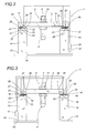
- each of the machining units 4, 5, which are of conventional type and therefore not illustrated in detail, comprises a slide 6, 7 that mounts a tool holder spindle 8, 9 shown in Figures 2 and 3.
- the slide 6, 7 is slidably engaged with a supporting element 10, 11 in which it runs in the direction Z.
- the supporting elements 10, 11 can move in the direction Y relative to the respective crossbeams 2, 3 through customary driving means which are not described in further detail.
- the two crossbeams 2 and 3 extend in a respective principal direction D1, D2 that is substantially parallel to the Y-axis of the Cartesian reference system.
- the two crossbeams 2, 3 are supported by two longitudinal guides 12, 13 extending in a principal direction D3 that is substantially parallel to the direction X, the guides 12, 13 being supported by a plurality of columns 14.
- the columns 14 have respective lower ends 15 connected to a base 16 of the machine tool 100 and respective upper ends 17 connected to the longitudinal guides 12, 13.
- the crossbeams 2, 3 can slide in the longitudinal guides 12, 13 in the direction D3 so as to guide the machining units 4, 5 in the movements the latter are required to perform in order to machine the workpieces in the automatic machine tool 100.
- the machine 100 comprises two numerical control units 40, 41 for controlling the machining units 4, 5 mounted on the crossbeams 2 and 3 so that the machine 100 can perform the required machining operations.
- the units 40, 41 are located at two columns 14 opposite each other in the direction D3.
- Each control unit 40, 41 can be programmed to make the respective machining unit 4, 5 perform a defined sequence of operations such as, for example, part programs, through specific software.
- control unit 40 is specifically dedicated to the machining unit 4 located on the first crossbeam 2, while the control unit 41 can control either only the machining unit 5 located on the second crossbeam 3, or both the machining units 4, 5, depending on the preset operating mode.
- the first crossbeam 2 is driven in the direction D3 by two linear electric motors 18, 19.
- Each of the two linear electric motors 18, 19 comprises a primary member or rotor 20 and a secondary member or stator 21.
- the two primary members 20 are integral with the first crossbeam 2 at the two opposite ends of it 22, 23.
- the two secondary members 21 consist of two respective parallel slideways 24, 25, each extending along one of the longitudinal guides 12, 13.
- the second crossbeam 3 is driven in the direction D3 by two linear electric motors 26, 27.
- Each of the two linear electric motors 26, 27 comprises a primary member or rotor 28 and a secondary member or stator 29.
- the two primary members 28 are integral with the second crossbeam 3 at the two opposite ends of it 30, 31.
- the two secondary members 29 consist of two respective parallel slideways 32, 33, each extending along one of the longitudinal guides 12, 13 and running parallel to and side by side with the slideways 24, 25 of the first crossbeam 2 on the inside of them in such a way as not to create interference between the two respective linear electric motors 18, 26, 19, 27 of each crossbeam 2, 3 running in the same longitudinal guide 12, 13.
- the respective primary members 20, 28 and secondary members 21, 29 of each motor 18, 19, 26, 27 are positioned opposite each other and separated by a suitable air gap 34 according to the known operating principle of linear electric motors.
- the linear electric motors 18, 19, 26, 27 constitute motor means labelled M in their entirety.
- each crossbeam 2, 3 comprises means, illustrated schematically in the drawings and labelled 38, for sliding the crossbeams 2, 3 in the longitudinal guides 12, 13.
- the means 38 which are of known type and not further described, are also designed to keep the air gap 34 between the primary member 20, 28 and the secondary members 21, 29 at a constant value.
- the machining units 4, 5 of the machine 100 are mounted on the mobile uprights 2', 3' instead of on the crossbeams 2, 3.
- Other components of the machine 100 illustrated in Figure 11 are the same in form and function as those already described with reference to Figures 1 to 10. For convenience, these components are labelled with the same reference numbers as those in Figures 1 to 10.
- the machining units 4, 5 mounted on the respective crossbeams 2, 3 of the machine tool 100 perform different operations on two respective workpieces 35, 36 positioned in two separate working areas.
- the machine 100 can, if necessary, perform completely different process cycles on completely different workpieces 35, 36.
- the two machining units 4, 5 work like two separate machine tools running different part programs.
- control unit 40 controls the machining unit 4 on the first crossbeam 2 and runs a first part program
- control unit 41 controls the machining unit 5 on the second crossbeam 3 and runs a second part program that differs from the first part program of the machining unit 4.
- the machine 100 makes it possible to perform the same process cycle on two identical workpieces 35 simultaneously and in a substantially synchronised manner, thus doubling the productivity of the machine 100 compared to a machine with only one machining unit.
- the control unit 41 controls both of the machining units 4, 5 on the crossbeams 2 and 3, running one part program only, while the control unit 40 remains idle.
- the machine 100 makes it possible to simultaneously perform different process cycles, where customary machines would perform them in succession. This reduces production time because it allows two different tools to be used simultaneously on the two machining units 4, 5.
- control unit 40 controls the machining unit 4 on the first crossbeam 2 and runs a first part program
- control unit 41 controls the machining unit 5 on the second crossbeam 3 and runs a second part program that differs from the first part program of the machining unit 4.
- the two machining units 4, 5 mounted on the two crossbeams 2, 3 of the machine tool 100 perform the same process cycle on a single workpiece 37 having two portions 37a, 37b that are symmetrical about an axis of symmetry S parallel to the direction D3.
- the machine 100 makes it possible to simultaneously perform identical process cycles, where customary machines would perform them in succession.
- control unit 41 controls both of the machining units 4, 5 on the crossbeams 2 and 3, running one part program only.
- the machine 100 enables the two machining units 4, 5 on the two crossbeams 2 and 3 to perform synchronised process cycles on two identical workpieces 35 extending lengthways principally in the direction D3 and positioned symmetrically about the direction D3 itself.
- the machine 100 enables the two machining units 4, 5 on the two crossbeams 2 and 3 to perform synchronised process cycles on two identical workpieces 35 positioned symmetrically about an axis S1 parallel to the direction D1.
- the machine 100 comprises an anticollision program set in at least one of the two control units 40, 41 and designed to prevent the two machining units 4,5 from colliding in the event of a programming error in one of the part programs or any other reason such as to apply a movement that causes the feed paths of the machining units 4, 5 to overlap in one of the directions D1, D2, D3.
- the anticollision program by monitoring the instantaneous positions of the two machining units 4, 5 using customary sensors, stops the relative movement of the machining units 4, 5 and, if necessary, generates visual and/or audible warning signals to alert the operator to the fault in the machine 100.
- the machining units 4, 5 are mounted on the uprights 2', 3'.
- the machine 100 operates in substantially the same way as that described above for the machine 100 equipped with mobile crossbeams 2, 3.
- its operating modes are similar to those described above with reference to Figures 4 to 10 and therefore they are not further described.
Landscapes
- Engineering & Computer Science (AREA)
- Mechanical Engineering (AREA)
- Machine Tool Units (AREA)
- Numerical Control (AREA)
- Finish Polishing, Edge Sharpening, And Grinding By Specific Grinding Devices (AREA)
- Multi-Process Working Machines And Systems (AREA)
- Perforating, Stamping-Out Or Severing By Means Other Than Cutting (AREA)
Applications Claiming Priority (2)
| Application Number | Priority Date | Filing Date | Title |
|---|---|---|---|
| ITBO010134 | 2001-03-13 | ||
| IT2001BO000134A ITBO20010134A1 (it) | 2001-03-13 | 2001-03-13 | Macchina utensile |
Publications (3)
| Publication Number | Publication Date |
|---|---|
| EP1240974A2 true EP1240974A2 (fr) | 2002-09-18 |
| EP1240974A3 EP1240974A3 (fr) | 2003-04-02 |
| EP1240974B1 EP1240974B1 (fr) | 2006-02-01 |
Family
ID=11439180
Family Applications (1)
| Application Number | Title | Priority Date | Filing Date |
|---|---|---|---|
| EP01830726A Expired - Lifetime EP1240974B1 (fr) | 2001-03-13 | 2001-11-27 | Machine-outil avec au moins deux unités d'usinage |
Country Status (7)
| Country | Link |
|---|---|
| US (1) | US6655884B2 (fr) |
| EP (1) | EP1240974B1 (fr) |
| CN (1) | CN2539596Y (fr) |
| AT (1) | ATE316843T1 (fr) |
| DE (1) | DE60116992T2 (fr) |
| ES (1) | ES2257394T3 (fr) |
| IT (1) | ITBO20010134A1 (fr) |
Cited By (11)
| Publication number | Priority date | Publication date | Assignee | Title |
|---|---|---|---|---|
| WO2007137690A1 (fr) * | 2006-05-30 | 2007-12-06 | Index-Werke Gmbh & Co. Kg Hahn & Tessky | Centre d'usinage rotatif |
| EP1992449A1 (fr) * | 2007-05-11 | 2008-11-19 | Paolino Bacci S.R.L. | Centre d'usinage et procédé d usinage |
| WO2011006517A1 (fr) | 2009-07-16 | 2011-01-20 | Festo Ag & Co. Kg | Machine de travail comportant au moins une unité d'entraînement |
| WO2011104132A3 (fr) * | 2010-02-24 | 2012-05-03 | Mag Europe Gmbh | Station d'usinage pour l'usinage de pales de rotor pour des éoliennes |
| CN106112054A (zh) * | 2016-08-24 | 2016-11-16 | 中冶辽宁德龙钢管有限公司 | 一种钢管打孔机装置及打孔方法 |
| CN106141263A (zh) * | 2015-03-24 | 2016-11-23 | 宁波天艺数控机械有限公司 | 一种加工细长杆件端面的数控雕铣机床 |
| EP3208033A3 (fr) * | 2010-11-03 | 2017-10-18 | Mubea Systems, Société Anonyme | Commande d'un dispositif destiné à usiner une pièce de grande taille |
| WO2018172061A1 (fr) * | 2017-03-20 | 2018-09-27 | Stama Maschinenfabrik Gmbh | Machine-outil comportant deux arbres d'outil |
| CN111687455A (zh) * | 2020-04-28 | 2020-09-22 | 东莞市固达机械制造有限公司 | 数控双侧铣床 |
| IT202000022525A1 (it) * | 2020-09-24 | 2022-03-24 | Vigel Spa | Centro di lavoro multiasse munito di magazzino-utensili meccanizzato. |
| WO2022063775A1 (fr) * | 2020-09-24 | 2022-03-31 | Vigel S.P.A. | Centre d'usinage multi-axes avec magasin d'outils mécanisé |
Families Citing this family (36)
| Publication number | Priority date | Publication date | Assignee | Title |
|---|---|---|---|---|
| ATE296709T1 (de) * | 2001-03-09 | 2005-06-15 | Cross Hueller Gmbh | Werkzeugmaschine |
| AU2003233599A1 (en) * | 2002-05-17 | 2003-12-02 | Anthony Salerno Jr. | Linear electric servo motor actuated screw thread tapper |
| ITTO20020445A1 (it) * | 2002-05-24 | 2003-11-24 | Bimatech S R L | Attrezzatura per la foratura di lastre di materiale fragile, in particolare lastre di vetro. |
| ITMI20040309U1 (it) * | 2004-06-23 | 2004-09-23 | Dario Toncelli | Macchina per la lavorazione di materiale in lastre in particolare di materiale lapideo naturale materiale ceramico e conglomerato |
| JP4427689B2 (ja) * | 2004-07-08 | 2010-03-10 | オークマ株式会社 | 工作機械 |
| ITBO20040657A1 (it) * | 2004-10-22 | 2005-01-22 | Jobs Spa | Macchina utensile pluriasse |
| US20060096437A1 (en) * | 2004-11-08 | 2006-05-11 | Billco Manufacturing, Inc. | Integrated glass cutting and laser marking table |
| ATE380090T1 (de) * | 2005-02-23 | 2007-12-15 | Kessler Kg Maschf | Bearbeitungsmaschine mit mehreren parallelen spindelanordnungen |
| US7523535B2 (en) * | 2005-11-16 | 2009-04-28 | Columbus Steel Castings Company | Railcar truck bolster side bearing mounting pad milling machine and method |
| CN101143467B (zh) * | 2007-09-21 | 2011-03-23 | 裴庭胜 | 板材钻孔设备 |
| WO2009093877A2 (fr) * | 2008-01-25 | 2009-07-30 | Centre d'usinage complexe | |
| KR100928287B1 (ko) | 2008-12-26 | 2009-11-25 | 김복인 | 브이컷의 다방향 동시 작업이 가능한 조각기 |
| KR100927207B1 (ko) * | 2008-12-26 | 2009-11-18 | 김복인 | 복수의 절개날을 갖는 조각기 |
| KR100910590B1 (ko) * | 2008-06-18 | 2009-08-03 | 김복인 | 양방향 이동이 가능한 다목적 조각기 |
| DE502008002765D1 (de) * | 2008-03-12 | 2011-04-14 | Schuler Automation Gmbh & Co | Vorrichtung und verfahren zum entstapeln von plattenförmigen teilen |
| US10384363B2 (en) * | 2009-01-26 | 2019-08-20 | Dennis R. Brown | Double blade meat slicer |
| KR100957609B1 (ko) * | 2009-03-30 | 2010-05-13 | 김복인 | 브이홈 전용 가공기 |
| CN102049556A (zh) * | 2011-01-21 | 2011-05-11 | 浙江双雕数控技术股份有限公司 | 数控双工位铣削中心 |
| WO2012127942A1 (fr) * | 2011-03-24 | 2012-09-27 | 村田機械株式会社 | Système de machine-outil |
| CN102773770A (zh) * | 2011-05-13 | 2012-11-14 | 常州纺织服装职业技术学院 | 一种基于流水线加工的机床 |
| CN102430993A (zh) * | 2011-11-02 | 2012-05-02 | 沈阳飞机工业(集团)有限公司 | 柔性装配工装 |
| CN102490022B (zh) * | 2011-12-15 | 2014-01-22 | 奇瑞汽车股份有限公司 | 一种多向调节的切割装置 |
| CN104209770A (zh) * | 2014-09-11 | 2014-12-17 | 杨文惠 | 一种工作台 |
| FR3033273B1 (fr) * | 2015-03-02 | 2017-08-18 | Airbus Operations Sas | Porte-outil fixe sur une piece |
| DE102015105043A1 (de) * | 2015-04-01 | 2016-10-06 | Samag Saalfelder Werkzeugmaschinen Gmbh | Bearbeitungsmaschine |
| DE202015009036U1 (de) * | 2015-05-06 | 2016-07-25 | Gehring Technologies Gmbh | Honmaschine mit einem Maschinengestell und mindestens zwei beidseits des Maschinengestells angeordneten Einheiten |
| CN104959834B (zh) * | 2015-06-12 | 2016-03-30 | 山东鑫宏光电科技有限公司 | 一种多功能平面立体雕刻切割焊接机 |
| DE102017129748A1 (de) * | 2017-12-13 | 2019-06-13 | Eurolaser Gmbh | Positionierungssystem und Materialbearbeitungsmaschine |
| CN108544245A (zh) * | 2018-06-26 | 2018-09-18 | 深圳市联合数控科技有限公司 | 多动梁式数控机床 |
| DE102018210507A1 (de) * | 2018-06-27 | 2020-01-02 | Airbus Operations Gmbh | Montagesystem für eine automatisierte Innenmontage eines Flugzeugrumpfes |
| US10722953B1 (en) * | 2019-01-18 | 2020-07-28 | Feng-Tien Chen | CNC milling machine combined with picking robotic arm unit |
| CN109940442B (zh) * | 2019-04-04 | 2024-05-24 | 科德数控股份有限公司 | 工件自动翻转加工的双工位龙门组合加工系统 |
| CN111515705A (zh) * | 2020-04-28 | 2020-08-11 | 珠海博杰电子股份有限公司 | 一种高速高精度单驱龙门结构 |
| USD1008322S1 (en) * | 2020-12-16 | 2023-12-19 | Guangdong Shangrila Networking Technology Co., Ltd. | CNC router |
| USD965650S1 (en) * | 2021-03-10 | 2022-10-04 | 3D Linux Systems Inc. | Multi-functional CNC machine structure |
| USD982624S1 (en) * | 2021-11-01 | 2023-04-04 | 4Robotics OÜ | Computer numerical control CNC machine tool |
Citations (5)
| Publication number | Priority date | Publication date | Assignee | Title |
|---|---|---|---|---|
| GB1416638A (en) * | 1972-11-25 | 1975-12-03 | Fujitsu Ltd | Pulse operated linear motor |
| US5293022A (en) * | 1991-11-04 | 1994-03-08 | Ona Electro-Erosion, S.A. | Spark erosion machine |
| EP0835720A1 (fr) * | 1996-10-11 | 1998-04-15 | Noran, S.L. | Fraiseuse à deux bras |
| EP1004397A2 (fr) * | 1998-11-26 | 2000-05-31 | Matsuura Machinery Co. Ltd | Dispositif d'usinage combiné |
| DE19963863A1 (de) * | 1999-12-30 | 2001-07-12 | Mikromat Werkzeugmaschinen Gmb | Bearbeitungsanlage für die spanende Bearbeitung von Freiformflächen an Werkstücken des Formen-, Gesenk-, Vorrichtungs- und Modellbaus |
Family Cites Families (7)
| Publication number | Priority date | Publication date | Assignee | Title |
|---|---|---|---|---|
| JPS6211570A (ja) * | 1985-07-05 | 1987-01-20 | Honda Motor Co Ltd | 自動塗布装置 |
| DE3809630C1 (fr) * | 1988-03-22 | 1989-05-18 | Duerkopp Systemtechnik Gmbh, 4800 Bielefeld, De | |
| JPH04250911A (ja) * | 1990-12-28 | 1992-09-07 | Ishikawajima Harima Heavy Ind Co Ltd | 門型切削機 |
| DE69107196T2 (de) * | 1991-04-05 | 1995-05-24 | Torres Martinez M | Werkzeugmaschineneinrichtung zum Einspannen und Bearbeiten. |
| US5393288A (en) * | 1991-11-26 | 1995-02-28 | Mutoh Industries Ltd. | Three-dimensional processing machine and a method of processing a workpiece |
| US5314397A (en) * | 1992-07-31 | 1994-05-24 | Ford Motor Company | Positioning apparatus for multiple-spindle machining |
| DE69838351T2 (de) * | 1997-07-24 | 2008-05-21 | Jtekt Corp., Osaka | Werkzeugmaschine |
-
2001
- 2001-03-13 IT IT2001BO000134A patent/ITBO20010134A1/it unknown
- 2001-11-27 EP EP01830726A patent/EP1240974B1/fr not_active Expired - Lifetime
- 2001-11-27 AT AT01830726T patent/ATE316843T1/de not_active IP Right Cessation
- 2001-11-27 DE DE60116992T patent/DE60116992T2/de not_active Expired - Lifetime
- 2001-11-27 ES ES01830726T patent/ES2257394T3/es not_active Expired - Lifetime
-
2002
- 2002-03-08 US US10/092,632 patent/US6655884B2/en not_active Expired - Lifetime
- 2002-03-13 CN CN02207451U patent/CN2539596Y/zh not_active Expired - Lifetime
Patent Citations (5)
| Publication number | Priority date | Publication date | Assignee | Title |
|---|---|---|---|---|
| GB1416638A (en) * | 1972-11-25 | 1975-12-03 | Fujitsu Ltd | Pulse operated linear motor |
| US5293022A (en) * | 1991-11-04 | 1994-03-08 | Ona Electro-Erosion, S.A. | Spark erosion machine |
| EP0835720A1 (fr) * | 1996-10-11 | 1998-04-15 | Noran, S.L. | Fraiseuse à deux bras |
| EP1004397A2 (fr) * | 1998-11-26 | 2000-05-31 | Matsuura Machinery Co. Ltd | Dispositif d'usinage combiné |
| DE19963863A1 (de) * | 1999-12-30 | 2001-07-12 | Mikromat Werkzeugmaschinen Gmb | Bearbeitungsanlage für die spanende Bearbeitung von Freiformflächen an Werkstücken des Formen-, Gesenk-, Vorrichtungs- und Modellbaus |
Cited By (17)
| Publication number | Priority date | Publication date | Assignee | Title |
|---|---|---|---|---|
| WO2007137690A1 (fr) * | 2006-05-30 | 2007-12-06 | Index-Werke Gmbh & Co. Kg Hahn & Tessky | Centre d'usinage rotatif |
| US7743689B2 (en) | 2006-05-30 | 2010-06-29 | Index-Werke Gmbh & Co. Kg Hahn & Tessky | Turning center |
| CN101454119B (zh) * | 2006-05-30 | 2013-05-01 | 哈恩和特斯基工件指数有限商业两合公司 | 车削加工中心 |
| EP1992449A1 (fr) * | 2007-05-11 | 2008-11-19 | Paolino Bacci S.R.L. | Centre d'usinage et procédé d usinage |
| WO2011006517A1 (fr) | 2009-07-16 | 2011-01-20 | Festo Ag & Co. Kg | Machine de travail comportant au moins une unité d'entraînement |
| WO2011104132A3 (fr) * | 2010-02-24 | 2012-05-03 | Mag Europe Gmbh | Station d'usinage pour l'usinage de pales de rotor pour des éoliennes |
| EP3208033A3 (fr) * | 2010-11-03 | 2017-10-18 | Mubea Systems, Société Anonyme | Commande d'un dispositif destiné à usiner une pièce de grande taille |
| CN106141263A (zh) * | 2015-03-24 | 2016-11-23 | 宁波天艺数控机械有限公司 | 一种加工细长杆件端面的数控雕铣机床 |
| CN106112054A (zh) * | 2016-08-24 | 2016-11-16 | 中冶辽宁德龙钢管有限公司 | 一种钢管打孔机装置及打孔方法 |
| CN106112054B (zh) * | 2016-08-24 | 2018-06-26 | 中冶辽宁德龙钢管有限公司 | 一种钢管打孔机装置及打孔方法 |
| WO2018172061A1 (fr) * | 2017-03-20 | 2018-09-27 | Stama Maschinenfabrik Gmbh | Machine-outil comportant deux arbres d'outil |
| US11229981B2 (en) | 2017-03-20 | 2022-01-25 | Stama Maschinenfabrik Gmbh | Machine tool having two tool spindles |
| US11618118B2 (en) | 2017-03-20 | 2023-04-04 | Stama Maschinenfabrik Gmbh | Machine tool having a tool spindle |
| CN111687455A (zh) * | 2020-04-28 | 2020-09-22 | 东莞市固达机械制造有限公司 | 数控双侧铣床 |
| IT202000022525A1 (it) * | 2020-09-24 | 2022-03-24 | Vigel Spa | Centro di lavoro multiasse munito di magazzino-utensili meccanizzato. |
| WO2022063775A1 (fr) * | 2020-09-24 | 2022-03-31 | Vigel S.P.A. | Centre d'usinage multi-axes avec magasin d'outils mécanisé |
| WO2022063777A1 (fr) * | 2020-09-24 | 2022-03-31 | Vigel S.P.A. | Centre d'usinage multi-axes doté d'un magasin d'outils mécanisé |
Also Published As
| Publication number | Publication date |
|---|---|
| EP1240974B1 (fr) | 2006-02-01 |
| CN2539596Y (zh) | 2003-03-12 |
| ES2257394T3 (es) | 2006-08-01 |
| ITBO20010134A0 (it) | 2001-03-13 |
| DE60116992T2 (de) | 2006-09-21 |
| US20020131836A1 (en) | 2002-09-19 |
| DE60116992D1 (de) | 2006-04-13 |
| US6655884B2 (en) | 2003-12-02 |
| EP1240974A3 (fr) | 2003-04-02 |
| ITBO20010134A1 (it) | 2002-09-13 |
| ATE316843T1 (de) | 2006-02-15 |
Similar Documents
| Publication | Publication Date | Title |
|---|---|---|
| EP1240974B1 (fr) | Machine-outil avec au moins deux unités d'usinage | |
| US11247303B2 (en) | Horizontal multi-spindle machining center | |
| US4984351A (en) | Machine tool | |
| US8769791B2 (en) | Machine tool | |
| EP2708312B1 (fr) | Centre d'usinage | |
| EP3089845B1 (fr) | Appareil d'usinage à cinq axes | |
| JP2008526521A (ja) | レーザ加工機 | |
| KR101724057B1 (ko) | W축 이송부를 구비한 멀티 스핀들 머시닝 센터 | |
| KR930703115A (ko) | 복합 공작 기계 | |
| KR101689404B1 (ko) | 복합선반 및 워크의 가공방법 | |
| KR870004782A (ko) | 수치제어 머시인 | |
| EP3907038B1 (fr) | Machine-outil et son procédé de fonctionnement | |
| KR20000023016A (ko) | 2개의 스핀들 헤드를 구비한 공작 기계 | |
| EP1247611B1 (fr) | Centre d'usinage à plusieurs axes, pour usinage multiple, en particulier pour le travail du bois | |
| US5559413A (en) | Screw shaft feed mechanism and positioning control method therefor | |
| KR20090111492A (ko) | 이중 스핀들 구조를 가지는 수평형 머시닝센터 | |
| JP2007094458A (ja) | 数値制御装置 | |
| JP2599392B2 (ja) | 二頭別制御のnc放電加工機 | |
| CA1234681A (fr) | Systeme d'assemblage programmable modulaire a prix modique | |
| JPH06246560A (ja) | 三次元板材複合加工装置 | |
| US20240165716A1 (en) | Lateral processing machine and lateral processing system | |
| KR20190115216A (ko) | 공구 교환 제어장치 및 제어방법 | |
| US11964330B2 (en) | Lathe | |
| GB2389808A (en) | Woodworking machine with automatic workpiece support and positioning | |
| WO2023048692A1 (fr) | Fraiseuse verticale |
Legal Events
| Date | Code | Title | Description |
|---|---|---|---|
| PUAI | Public reference made under article 153(3) epc to a published international application that has entered the european phase |
Free format text: ORIGINAL CODE: 0009012 |
|
| AK | Designated contracting states |
Kind code of ref document: A2 Designated state(s): AT BE CH CY DE DK ES FI FR GB GR IE IT LI LU MC NL PT SE TR |
|
| AX | Request for extension of the european patent |
Free format text: AL;LT;LV;MK;RO;SI |
|
| PUAL | Search report despatched |
Free format text: ORIGINAL CODE: 0009013 |
|
| AK | Designated contracting states |
Kind code of ref document: A3 Designated state(s): AT BE CH CY DE DK ES FI FR GB GR IE IT LI LU MC NL PT SE TR |
|
| AX | Request for extension of the european patent |
Extension state: AL LT LV MK RO SI |
|
| 17P | Request for examination filed |
Effective date: 20030627 |
|
| AKX | Designation fees paid |
Designated state(s): AT BE CH CY DE DK ES FI FR GB GR IE IT LI LU MC NL PT SE TR |
|
| 17Q | First examination report despatched |
Effective date: 20031204 |
|
| GRAP | Despatch of communication of intention to grant a patent |
Free format text: ORIGINAL CODE: EPIDOSNIGR1 |
|
| GRAS | Grant fee paid |
Free format text: ORIGINAL CODE: EPIDOSNIGR3 |
|
| GRAA | (expected) grant |
Free format text: ORIGINAL CODE: 0009210 |
|
| AK | Designated contracting states |
Kind code of ref document: B1 Designated state(s): AT BE CH CY DE DK ES FI FR GB GR IE IT LI LU MC NL PT SE TR |
|
| PG25 | Lapsed in a contracting state [announced via postgrant information from national office to epo] |
Ref country code: IT Free format text: LAPSE BECAUSE OF FAILURE TO SUBMIT A TRANSLATION OF THE DESCRIPTION OR TO PAY THE FEE WITHIN THE PRE;WARNING: LAPSES OF ITALIAN PATENTS WITH EFFECTIVE DATE BEFORE 2007 MAY HAVE OCCURRED AT ANY TIME BEFORE 2007. THE CORRECT EFFECTIVE DATE MAY BE DIFFERENT FROM THE ONE RECORDED.SCRIBED TIME-LIMIT Effective date: 20060201 Ref country code: FI Free format text: LAPSE BECAUSE OF FAILURE TO SUBMIT A TRANSLATION OF THE DESCRIPTION OR TO PAY THE FEE WITHIN THE PRESCRIBED TIME-LIMIT Effective date: 20060201 Ref country code: CH Free format text: LAPSE BECAUSE OF FAILURE TO SUBMIT A TRANSLATION OF THE DESCRIPTION OR TO PAY THE FEE WITHIN THE PRESCRIBED TIME-LIMIT Effective date: 20060201 Ref country code: BE Free format text: LAPSE BECAUSE OF FAILURE TO SUBMIT A TRANSLATION OF THE DESCRIPTION OR TO PAY THE FEE WITHIN THE PRESCRIBED TIME-LIMIT Effective date: 20060201 Ref country code: AT Free format text: LAPSE BECAUSE OF FAILURE TO SUBMIT A TRANSLATION OF THE DESCRIPTION OR TO PAY THE FEE WITHIN THE PRESCRIBED TIME-LIMIT Effective date: 20060201 Ref country code: LI Free format text: LAPSE BECAUSE OF FAILURE TO SUBMIT A TRANSLATION OF THE DESCRIPTION OR TO PAY THE FEE WITHIN THE PRESCRIBED TIME-LIMIT Effective date: 20060201 Ref country code: NL Free format text: LAPSE BECAUSE OF FAILURE TO SUBMIT A TRANSLATION OF THE DESCRIPTION OR TO PAY THE FEE WITHIN THE PRESCRIBED TIME-LIMIT Effective date: 20060201 |
|
| REG | Reference to a national code |
Ref country code: GB Ref legal event code: FG4D |
|
| REG | Reference to a national code |
Ref country code: CH Ref legal event code: EP |
|
| REG | Reference to a national code |
Ref country code: IE Ref legal event code: FG4D |
|
| REF | Corresponds to: |
Ref document number: 60116992 Country of ref document: DE Date of ref document: 20060413 Kind code of ref document: P |
|
| PG25 | Lapsed in a contracting state [announced via postgrant information from national office to epo] |
Ref country code: SE Free format text: LAPSE BECAUSE OF FAILURE TO SUBMIT A TRANSLATION OF THE DESCRIPTION OR TO PAY THE FEE WITHIN THE PRESCRIBED TIME-LIMIT Effective date: 20060501 Ref country code: DK Free format text: LAPSE BECAUSE OF FAILURE TO SUBMIT A TRANSLATION OF THE DESCRIPTION OR TO PAY THE FEE WITHIN THE PRESCRIBED TIME-LIMIT Effective date: 20060501 |
|
| NLV1 | Nl: lapsed or annulled due to failure to fulfill the requirements of art. 29p and 29m of the patents act | ||
| PG25 | Lapsed in a contracting state [announced via postgrant information from national office to epo] |
Ref country code: PT Free format text: LAPSE BECAUSE OF FAILURE TO SUBMIT A TRANSLATION OF THE DESCRIPTION OR TO PAY THE FEE WITHIN THE PRESCRIBED TIME-LIMIT Effective date: 20060703 |
|
| REG | Reference to a national code |
Ref country code: ES Ref legal event code: FG2A Ref document number: 2257394 Country of ref document: ES Kind code of ref document: T3 |
|
| REG | Reference to a national code |
Ref country code: CH Ref legal event code: PL |
|
| ET | Fr: translation filed | ||
| PG25 | Lapsed in a contracting state [announced via postgrant information from national office to epo] |
Ref country code: IE Free format text: LAPSE BECAUSE OF NON-PAYMENT OF DUE FEES Effective date: 20061127 |
|
| PG25 | Lapsed in a contracting state [announced via postgrant information from national office to epo] |
Ref country code: MC Free format text: LAPSE BECAUSE OF NON-PAYMENT OF DUE FEES Effective date: 20061130 |
|
| PLBE | No opposition filed within time limit |
Free format text: ORIGINAL CODE: 0009261 |
|
| STAA | Information on the status of an ep patent application or granted ep patent |
Free format text: STATUS: NO OPPOSITION FILED WITHIN TIME LIMIT |
|
| 26N | No opposition filed |
Effective date: 20061103 |
|
| PG25 | Lapsed in a contracting state [announced via postgrant information from national office to epo] |
Ref country code: GR Free format text: LAPSE BECAUSE OF FAILURE TO SUBMIT A TRANSLATION OF THE DESCRIPTION OR TO PAY THE FEE WITHIN THE PRESCRIBED TIME-LIMIT Effective date: 20060502 |
|
| PG25 | Lapsed in a contracting state [announced via postgrant information from national office to epo] |
Ref country code: LU Free format text: LAPSE BECAUSE OF NON-PAYMENT OF DUE FEES Effective date: 20061127 Ref country code: TR Free format text: LAPSE BECAUSE OF FAILURE TO SUBMIT A TRANSLATION OF THE DESCRIPTION OR TO PAY THE FEE WITHIN THE PRESCRIBED TIME-LIMIT Effective date: 20060201 |
|
| PG25 | Lapsed in a contracting state [announced via postgrant information from national office to epo] |
Ref country code: CY Free format text: LAPSE BECAUSE OF FAILURE TO SUBMIT A TRANSLATION OF THE DESCRIPTION OR TO PAY THE FEE WITHIN THE PRESCRIBED TIME-LIMIT Effective date: 20060201 |
|
| REG | Reference to a national code |
Ref country code: FR Ref legal event code: PLFP Year of fee payment: 15 |
|
| REG | Reference to a national code |
Ref country code: FR Ref legal event code: PLFP Year of fee payment: 16 |
|
| REG | Reference to a national code |
Ref country code: FR Ref legal event code: PLFP Year of fee payment: 17 |
|
| PGFP | Annual fee paid to national office [announced via postgrant information from national office to epo] |
Ref country code: GB Payment date: 20181130 Year of fee payment: 18 Ref country code: IT Payment date: 20181123 Year of fee payment: 18 Ref country code: ES Payment date: 20181218 Year of fee payment: 18 Ref country code: FR Payment date: 20181129 Year of fee payment: 18 |
|
| PGFP | Annual fee paid to national office [announced via postgrant information from national office to epo] |
Ref country code: DE Payment date: 20190131 Year of fee payment: 18 |
|
| REG | Reference to a national code |
Ref country code: DE Ref legal event code: R119 Ref document number: 60116992 Country of ref document: DE |
|
| GBPC | Gb: european patent ceased through non-payment of renewal fee |
Effective date: 20191127 |
|
| PG25 | Lapsed in a contracting state [announced via postgrant information from national office to epo] |
Ref country code: DE Free format text: LAPSE BECAUSE OF NON-PAYMENT OF DUE FEES Effective date: 20200603 Ref country code: GB Free format text: LAPSE BECAUSE OF NON-PAYMENT OF DUE FEES Effective date: 20191127 Ref country code: FR Free format text: LAPSE BECAUSE OF NON-PAYMENT OF DUE FEES Effective date: 20191130 Ref country code: IT Free format text: LAPSE BECAUSE OF NON-PAYMENT OF DUE FEES Effective date: 20191127 |
|
| REG | Reference to a national code |
Ref country code: ES Ref legal event code: FD2A Effective date: 20210528 |
|
| PG25 | Lapsed in a contracting state [announced via postgrant information from national office to epo] |
Ref country code: ES Free format text: LAPSE BECAUSE OF NON-PAYMENT OF DUE FEES Effective date: 20191128 |