EP1240538B1 - Multi-channel fiber-optic rotary joint - Google Patents
Multi-channel fiber-optic rotary joint Download PDFInfo
- Publication number
- EP1240538B1 EP1240538B1 EP00993543A EP00993543A EP1240538B1 EP 1240538 B1 EP1240538 B1 EP 1240538B1 EP 00993543 A EP00993543 A EP 00993543A EP 00993543 A EP00993543 A EP 00993543A EP 1240538 B1 EP1240538 B1 EP 1240538B1
- Authority
- EP
- European Patent Office
- Prior art keywords
- gear
- prism
- rotary joint
- pluralities
- hollow shaft
- Prior art date
- Legal status (The legal status is an assumption and is not a legal conclusion. Google has not performed a legal analysis and makes no representation as to the accuracy of the status listed.)
- Expired - Lifetime
Links
- 239000000835 fiber Substances 0.000 claims description 25
- 238000004519 manufacturing process Methods 0.000 claims description 2
- 230000003287 optical effect Effects 0.000 claims description 2
- 239000013307 optical fiber Substances 0.000 claims 7
- 238000005457 optimization Methods 0.000 description 7
- 230000000694 effects Effects 0.000 description 6
- 230000007246 mechanism Effects 0.000 description 5
- 230000008901 benefit Effects 0.000 description 1
- 238000010276 construction Methods 0.000 description 1
- 239000012634 fragment Substances 0.000 description 1
- 230000008676 import Effects 0.000 description 1
- 239000002184 metal Substances 0.000 description 1
- 230000004048 modification Effects 0.000 description 1
- 238000012986 modification Methods 0.000 description 1
- 230000008707 rearrangement Effects 0.000 description 1
- 238000009877 rendering Methods 0.000 description 1
Images


Classifications
-
- G—PHYSICS
- G02—OPTICS
- G02B—OPTICAL ELEMENTS, SYSTEMS OR APPARATUS
- G02B6/00—Light guides; Structural details of arrangements comprising light guides and other optical elements, e.g. couplings
- G02B6/24—Coupling light guides
- G02B6/36—Mechanical coupling means
- G02B6/3604—Rotary joints allowing relative rotational movement between opposing fibre or fibre bundle ends
-
- Y—GENERAL TAGGING OF NEW TECHNOLOGICAL DEVELOPMENTS; GENERAL TAGGING OF CROSS-SECTIONAL TECHNOLOGIES SPANNING OVER SEVERAL SECTIONS OF THE IPC; TECHNICAL SUBJECTS COVERED BY FORMER USPC CROSS-REFERENCE ART COLLECTIONS [XRACs] AND DIGESTS
- Y10—TECHNICAL SUBJECTS COVERED BY FORMER USPC
- Y10S—TECHNICAL SUBJECTS COVERED BY FORMER USPC CROSS-REFERENCE ART COLLECTIONS [XRACs] AND DIGESTS
- Y10S359/00—Optical: systems and elements
- Y10S359/90—Methods
Definitions
- This invention relates to a multi-channel fiber-optic rotary joint and, more particularly, to a rotary joint, as aforesaid, wherein an adjustment mechanism is provided for optimizing the signal strength transmitted through the rotary joint from one set of fiber strands in an bundle to another set of fiber strands in a separate bundle disposed axially from the first bundle.
- Multi-channel fiber-optic rotary joints are known in the art and one example thereof is described in U.S. Patent No. 5 271 076. As is explained in this patent, the extreme tolerances associated with multi-channel rotary joints exhibit high optical loss and variation of that loss with rotation.
- EP A 0 111 390 discloses a multi-channel fiber-optic rotary joint.
- a multi-channel fiber-optic rotary joint according to the present invention is defined by the features set out in claim 1.
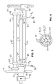
- a multi-channel fiber-optic rotary joint 10 is illustrated in Figure 1. It includes a housing 11 having an elongate passageway 12 extending axially therethrough.
- the housing 11 consists of two housing parts 11A and 11B that are coupled together by a plurality of screws (not illustrated). When the housing parts 11A and 11B are assembled, a cylindrical housing is defined with an axially extending passageway 12 extending therethrough.
- the left end of the housing illustrated in Figure 1 includes a support section 13 for rotatably supporting a hollow shaft 14 in plural coaxially oriented bearings 16.
- a spur gear 17 is oriented between the bearing sets 16 as illustrated in Figure 1 and projects through a gap 18 in the support section 13.
- the left end of the hollow shaft 14 terminates in a radial flange 19, which flange can be used for securing the hollow shaft 14 to either a fixed or rotatable member not illustrated.
- the right end of the housing 11 includes a support section 21 rotatably supporting a hollow shaft 22 on sets of bearings 23 supported on the support section 21.
- a spur gear 24 identical in size and having an equal number of teeth as the spur gear 17 is mounted on the hollow shaft 22 and oriented between the sets of bearings 23 as illustrated in Figure 1.
- the axis of rotation 26 of the hollow shaft 14 is coaxial with the axis of rotation 27 of the hollow shaft 22.
- a radial flange 25 is mounted on the hollow shaft 22 in a manner similar to the radial flange 19 on the hollow shaft 14. As with the radial flange 19, the radial flange 25 also provides facilitation of a mounting to either a fixed or rotatable member.
- the leftmost bearing 23 has a radially outwardly extending flange 23A which is received in a groove 23B in the support section 21.
- a load ring 23C is threadedly engaged with the support section 21 immediately to the right of the rightmost bearing 23 and, when turned, effects an application of an axial force on the rightmost bearing and directed toward the radial flange 23A to compress the bearings 23 and the hub for the spur gear 24 therebetween.
- This axially applied force also removes-any unwanted radial play or clearance in the bearings 23 so as to keep the position of the axis of the shaft 22 from varying in the support structure 13.
- the rightmost bearing 16 has a radially outwardly extending flange 16A thereon received in a not illustrated groove in the support section 13, which is similar to the groove 23B in the support section 21.
- a load ring 16B is threadedly secured to the support section 13 to effect, when turned, an application of an axial force toward the radial flange 16A to compress the bearings 16 and the hub for the spur gear 17 therebetween to accomplish the same objective as was done with the bearings 23.
- a plurality of fiber optic strands 28 and 29 forming a bundle 30 are oriented in each of the hollow shafts 14 and 22.
- the central fiber optic strand 28 of the fiber optic bundle 30 in each of the hollow shafts 14 and 22 is oriented centrally of the hollow shaft whereas the remaining, here six, fiber optic strands 29 are oriented circumferentially thereof as illustrated in Figure 6.
- a 7-channel rotary joint each channel being designated by a single fiber optic strand.
- the adjustable prism apparatus 31 is oriented in the signal path transitioning between the terminal ends of the fiber optic strands 28 and 29 in both bundles.
- the adjustable prism apparatus 31 includes a prism stage 32 best illustrated in Figures 2-4.
- the prism stage 32 includes an elongated base wall 33 and a pair of upstanding and parallel sidewalls 34 and 36 upstanding from the lateral edges of the base wall 33.
- the sidewall 36 has a reduced thickness section 37 in which is housed a leaf spring 38 bowing inwardly into the lateral space between the sidewalls 34 and 36.
- the bottom wall 33 has an opening 39 in generally the central region thereof adjacent the right end.
- the bottom wall also includes a laterally extending groove 41 adjacent the left end.
- the groove 41 opens through the bottom portion of the sidewall 36 as at 42.
- a pin 43 is received into the opening 42 and the groove 41 so that the upper surface thereof projects above the surface of the bottom wall 33 as illustrated in Figure 3.
- the upstanding wall 34 has at the end thereof adjacent the hole 39 an upstanding groove 44 adapted to receive therein a pin 46 as illustrated in Figure 2.
- a hole 47 is provided in the upstanding sidewall 34 adjacent the groove 41. The aforesaid holes 39 and 47 are adapted to receive a threaded set screw for applying respective forces onto the prism yet to be described.
- a post 48 depends downwardly from the underside of the base wall 33.
- the base wall is also provided with upstanding stops 49 adjacent the longitudinal ends thereof.
- a region between the terminal ends of the fiber optic strands 28 and 29 of the bundles 30 in the respective hollow shafts 14 and 22 includes a recess 51 having upstanding sidewalls, only one sidewall 52 being illustrated in Figure 2, end walls 53 and 54 and a bottom wall 56.
- the bottom wall 56 includes a pocket 57, polygonal in cross section, with a hole 58 extending from the bottom wall thereof.
- the hole 58 is adapted to receive an externally threaded set screw.
- the prism stage 32 is inserted into the recess 51 with the post 48 being slidingly received into the pocket 57.
- the sidewalls 34 and 36 of the prism stage 32 slidingly engage the sidewalls 52 of the recess 51.
- the post 48 has a polygonal cross section and corresponds to the polygonal cross section of the pocket 57 so as to prevent the prism stage from pivoting about an upright axis defined by the longitudinal axis of the post 48.
- a dove prism 61 is received in the space between the sidewalls 34 and 36 of the prism stage 32 as illustrated in Figures 1 and 2.
- Dove prisms are also known as reversion prisms. The entry and exit faces are inclined and are anti-reflection coated. The width of the dove prism is slightly less than the spacing between the upstanding sidewalls 34 and 36 of the prism stage 32 so that the spring 38 will urge the dove prism against the sidewall 34 while maintaining a small space between the sidewall of the dove prism and the sidewall 36 of the prism stage.
- a turning of a set screw in the hole 47 will apply a force F 1 to the corresponding side of the dove prism 61 to cause the dove prism 61 to pivot about a vertically upright axis defined by the pin 46.
- the turning of a set screw in the hole 58 will apply a force F 2 to the bottom end of the post 48 to raise and lower the prism stage 32.
- Turning of a set screw in the hole 39 will generate a force F 3 on one end of the dove prism 61 to cause the dove prism 61 to tilt about the axis defined by the pin 43.
- a spring 62 schematically illustrated in Figure 2 applies a downwardly directed force F 4 onto the top surface of the dove prism 61 so that when the respective set screws in the holes 39 and 58 are backed-off, the spring force F 4 will be sufficient to return the dove prism 61 to an original position thereof.
- a backing off of the set screw in the hole 47 will enable the spring 38 to return the dove prism laterally to the original position thereof about the upright pivot axis defined by the pin 46.
- the stops 49 retain the dove prism 61 therebetween and prevent a longitudinal shifting of the dove prism 61 relative to the housing 11.
- a signal S 1 exiting the central fiber optic strand 28 in the hollow shaft 14 can be adjusted so that the output signal S 2 from the dove prism 61 will be optimized into the central fiber optic strand 28 oriented in the hollow shaft 22.
- the signal strength from the outer fiber optic strands 29 oriented in the hollow shaft 14 now need to be optimized into the fiber optic strands 29 oriented in the hollow shaft 22.
- the following structure accomplishes that objective.
- the thickness of the wall of the housing part 11A is reduced as at 62 and 63 so that the spur gears 17 and 24 project through their respective gaps 18, 20 into the regions 62 and 63.
- Three longitudinally extending holes are cut lengthwise through the wall thickness of the housing part 11A, only two of the holes 64 and 66 being illustrated in Figure 1. The third not illustrated hole is immediately adjacent the hole 64. All three holes open into the respective regions 62 and 63.
- the hole 66 receives therein an elongate shaft 67 rotatably supported on spaced bearings 68.
- a spur gear 69 is secured to the end of the shaft 67 adjacent the exposed portion of the spur gear 17 projecting through the gap 18.
- An elongate shaft 71 is received into the hole 64 and is rotatably supported thereon by axially spaced bearings 72.
- a spur gear 73 identical to the spur gear 69 is secured to the right end of the shaft 71 and is oriented adjacent the exposed portion of the spur gear 24 projecting through the gap 20.
- a spur gear 74 is secured to the end of the shaft 71 adjacent both of the spur gears 17 and 69 and has a sufficient width to enable the teeth thereof to mesh with the teeth of the spur gears 17 and 69.
- a spring 76 schematically illustrated in Figure 5, applies a force F 5 on the bearing 72 to urge the spur gear 74 into tight engagement with the teeth on both of the spur gears 17 and 69 so as to eliminate any backlash that might be present therebetween.
- a unique feature of the gear 74 is that it is secured to a collet mechanism 77 which supports the gear 74 for rotation with respect to the shaft 71.
- the gear 74 can be rendered fixed to the shaft 71 by tightening the screw 78 on the collet mechanism 77. In other words, a loosening of the screw 78 will enable the collet to slip with respect to the shaft 71 thereby enabling the gear 74 to freely rotate with respect to the shaft 71.
- An elongate shaft 79 is received into the hole 65 ( Figure 5), namely, that hole which is behind the shaft 64 illustrated in Figure 1, and is rotatably supported in the hole 65 by axially spaced bearings 81.
- a gear 82 identical to the gear 74 is fixedly secured to the end of the shaft 79 adjacent the exposed portion of the spur gear 24 projecting through the gap 20 and the spur gear 73.
- the teeth on the spur gear 82 are meshed with the teeth on the spur gears 24 and 73.
- a spring 83 applies a force F 6 onto the bearing 81 adjacent the spur gear 82 so as to effect an urging of the teeth of the spur gear 82 into a tightly meshed relation with the teeth on the spur gears 24 and 73 in order to eliminate any backlash that may be present therebetween.
- FIG. 7 shows very schematically the loading scheme for achieving an antibacklash condition for all three gears.
- This loading scheme applies to gears of differing diameters as long as the pitch of the teeth is the same.
- gears 17, 24 and 69, 73 are not in the same plane and do not mesh.
- Gears 74, 82 are long enough (into the page) to mesh with both gears 17, 24 and 69, 73.
- Gears 17, 24 and 69, 73 have fixed rotation centers.
- gears 74, 82 cannot have a fixed rotation center since small eccentricities in manufacture would cause very high stresses in the gear teeth that would cause high friction, yield in the metal tooth face, or both.
- the gears and their respective shafts are simply too rigid to allow for even small eccentricities in the gears.
- a lateral load is supplied by a spring which is designed to be compliant enough not to yield while supplying enough load to maintain two tooth contact between gears 17, 24 and gears 74, 82 and gears 69, 73 and gears 74, 82.
- Figure 8 shows the effect of this arrangement.
- the pitch circle of gears 74, 82 rides in the v-angle formed by the two tangent lines of contact.
- antibacklash is achieved by using two gears in a scissors arrangement, but this type of antibacklash device cannot maintain the antibacklash effect between two gears simultaneously.
- the device presented here can. It also has an advantage in that the spring used to provide the lateral load can be designed independently of the gear set. Thus, the spring load can be corrected to an appropriate setting without starting from scratch on the gear set.
- the adjustable prism apparatus 31 described above has facilitated an optimization of the signal strength transfer between the central fiber optic strand 28 in the fiber optic bundle 30 oriented in the hollow shaft 14 to or from the central fiber optic strand 28 in the fiber optic bundle 30 oriented in the hollow shaft 22, the next adjustment that needs to occur is an optimization of the signal strength transfer between the outer fiber optic strands 29 in both bundles.
- This adjustment is accomplished in the following manner.
- the screw 78 is loosened so that the collet mechanism 77 facilitates the free rotation of the spur gear 74 relative to the shaft 71.
- the spur gear 24 can now be rotated relative to the spur gear 17 until signal strength optimization occurs with the outer fiber optic strands 29.
- This rotation of the housing 11 is caused by the spur gear 24 rotating relative to the spur gear 17 to cause the spur gears 82 and 73 to transmit a rotative force through the shaft 71 to the spur gear 74 to the teeth on the fixed spur gear 17.
- the rotating spur gear 74 will effect a rotative drive of the housing 11 in a direction of rotation that is the same as that of the spur gear 24 but half as fast.
Landscapes
- Physics & Mathematics (AREA)
- General Physics & Mathematics (AREA)
- Optics & Photonics (AREA)
- Mechanical Coupling Of Light Guides (AREA)
- Optical Couplings Of Light Guides (AREA)
- Mechanical Light Control Or Optical Switches (AREA)
- Investigating Materials By The Use Of Optical Means Adapted For Particular Applications (AREA)
- Sewing Machines And Sewing (AREA)
- Gears, Cams (AREA)
Priority Applications (1)
| Application Number | Priority Date | Filing Date | Title |
|---|---|---|---|
| DK00993543T DK1240538T3 (da) | 1999-12-20 | 2000-12-19 | Fiberoptisk multikanalrotationsled |
Applications Claiming Priority (3)
| Application Number | Priority Date | Filing Date | Title |
|---|---|---|---|
| US09/468,052 US6301405B1 (en) | 1999-12-20 | 1999-12-20 | Multi-channel fiber-optic rotary joint |
| US468052 | 1999-12-20 | ||
| PCT/US2000/034845 WO2001046728A2 (en) | 1999-12-20 | 2000-12-19 | Multi-channel fiber-optic rotary joint |
Publications (2)
| Publication Number | Publication Date |
|---|---|
| EP1240538A2 EP1240538A2 (en) | 2002-09-18 |
| EP1240538B1 true EP1240538B1 (en) | 2005-05-04 |
Family
ID=23858256
Family Applications (1)
| Application Number | Title | Priority Date | Filing Date |
|---|---|---|---|
| EP00993543A Expired - Lifetime EP1240538B1 (en) | 1999-12-20 | 2000-12-19 | Multi-channel fiber-optic rotary joint |
Country Status (9)
| Country | Link |
|---|---|
| US (1) | US6301405B1 (enExample) |
| EP (1) | EP1240538B1 (enExample) |
| JP (1) | JP4620314B2 (enExample) |
| AU (1) | AU769626B2 (enExample) |
| CA (1) | CA2393969C (enExample) |
| DE (1) | DE60019966T2 (enExample) |
| HK (1) | HK1049886B (enExample) |
| NO (1) | NO334603B1 (enExample) |
| WO (1) | WO2001046728A2 (enExample) |
Families Citing this family (23)
| Publication number | Priority date | Publication date | Assignee | Title |
|---|---|---|---|---|
| US7217417B2 (en) * | 2002-05-20 | 2007-05-15 | Dermacia, Inc. | Gel-based cosmetic and wound-healing formulation and method |
| US6895137B2 (en) | 2002-06-07 | 2005-05-17 | Infraredx, Inc. | Multi-channel optical coupler for spinning catheter |
| US7142747B2 (en) * | 2003-08-12 | 2006-11-28 | Moog Inc. | Fiber optic rotary joint and associated alignment method |
| CN100583741C (zh) * | 2003-09-04 | 2010-01-20 | 学校法人同志社 | 无线通信系统 |
| US20070019908A1 (en) * | 2005-07-22 | 2007-01-25 | Focal Technologies Corporation | Fiber optic rotary joint with de-rotating prism |
| DE102006011526A1 (de) * | 2006-03-10 | 2007-09-13 | Schleifring Und Apparatebau Gmbh | Optische Drehkupplung |
| DE102005056899B4 (de) | 2005-11-28 | 2007-10-18 | Schleifring Und Apparatebau Gmbh | Polarisationserhaltende optische Drehkupplung |
| WO2008077624A1 (de) * | 2006-12-22 | 2008-07-03 | Schleifring Und Apparatebau Gmbh | Optischer drehübertrager mit hoher rückflussdämpfung |
| DE102007013923B4 (de) | 2006-12-22 | 2012-02-02 | Schleifring Und Apparatebau Gmbh | Mehrkanaliger optischer Drehübertrager mit hoher Rückflußdämpfung |
| DE102007012224A1 (de) | 2007-03-12 | 2008-09-25 | Schleifring Und Apparatebau Gmbh | Mehrkanalige reflexionsarme optische Drehkupplung |
| DE102007029503A1 (de) | 2007-06-25 | 2009-01-02 | Schleifring Und Apparatebau Gmbh | Optischer Drehübertrager mit kurzer Baulänge |
| JP5276112B2 (ja) * | 2007-11-20 | 2013-08-28 | シーメンス アクチエンゲゼルシヤフト | 機械 |
| DE102009026632A1 (de) | 2008-06-06 | 2009-12-10 | Schleifring Und Apparatebau Gmbh | Linsenanordnung mit Lagejustierung |
| RU2402051C2 (ru) * | 2008-12-04 | 2010-10-20 | Закрытое акционерное общество "МНИТИ" (ЗАО "МНИТИ") | Универсальный волоконно-оптический вращающийся соединитель |
| EP2362948B1 (en) | 2008-12-11 | 2019-02-20 | Moog Inc. | High-power collimating lens assemblies, and methods of reducing the optical power density in collimating lens assemblies |
| US9409036B2 (en) | 2010-07-19 | 2016-08-09 | Wake Forest University Health Sciences | Implantable connector systems having magnetic portions thereon and related methods |
| US8554029B2 (en) | 2010-07-20 | 2013-10-08 | Princetel, Inc. | Through-bore fiber optic slipring |
| US8355607B2 (en) * | 2010-10-06 | 2013-01-15 | Princetel Inc. | Fiber optic rotary joint mechanism |
| US8417075B2 (en) * | 2011-01-05 | 2013-04-09 | Princetel, Inc. | Multi-channel electro-magnetic rotary joint using a trapezoidal metamaterial de-rotating mechanism |
| CA2982956C (en) | 2015-04-15 | 2023-08-01 | Moog Inc. | Optical rotary electrical connection |
| EP3182180B1 (en) | 2015-12-17 | 2024-01-24 | Schleifring GmbH | Multichannel fiber optic rotary joint(forj) having an achromatic metasurface |
| JP7217282B2 (ja) | 2018-03-01 | 2023-02-02 | ムーグ インコーポレーテッド | 複数パス式の光ファイバー・ロータリー・ジョイント |
| US11835770B2 (en) | 2020-01-24 | 2023-12-05 | ChiSquare Bioimaging LLC | Automated fiber optic rotary joint |
Family Cites Families (10)
| Publication number | Priority date | Publication date | Assignee | Title |
|---|---|---|---|---|
| JPS59105608A (ja) * | 1912-08-01 | 1984-06-19 | スペリ−・コ−ポレイシヨン | 光フアイバ用回転接合装置 |
| FR2580084B1 (enExample) * | 1985-04-05 | 1987-05-15 | Thomson Csf | |
| JPS63116116A (ja) * | 1986-11-05 | 1988-05-20 | Fujikura Ltd | 光伝送路の瞬時切換方法及びそれに用いる切換用素子 |
| JPH03156406A (ja) * | 1989-11-15 | 1991-07-04 | Hitachi Cable Ltd | 多心光ロータリジョイント |
| JPH0328807A (ja) * | 1990-05-18 | 1991-02-07 | Hitachi Cable Ltd | 多芯光ロータリジョイント |
| JP2780487B2 (ja) * | 1990-11-30 | 1998-07-30 | 日立電線株式会社 | 多心光ロータリージョイント |
| EP0488205B1 (en) * | 1990-11-28 | 1997-07-16 | Hitachi Cable, Ltd. | Multi-port fiberoptic rotary joint |
| US5271076A (en) | 1992-10-05 | 1993-12-14 | The United States Of America As Represented By The Secretary Of The Navy | Method providing optimum optical trains alignment in a passive multi-channel fiber optic rotary joint |
| US5442721A (en) * | 1994-08-08 | 1995-08-15 | The United States Of America As Represented By The Secretary Of The Navy | Fiber-optic rotary joint with bundle collimator assemblies |
| US5568578A (en) * | 1994-12-14 | 1996-10-22 | The United States Of America As Represented By The Secretary Of The Navy | Gradient index rod collimation lens devices for enhancing optical fiber line performance where the beam thereof crosses a gap in the line |
-
1999
- 1999-12-20 US US09/468,052 patent/US6301405B1/en not_active Expired - Lifetime
-
2000
- 2000-12-19 HK HK03101977.2A patent/HK1049886B/en not_active IP Right Cessation
- 2000-12-19 AU AU29108/01A patent/AU769626B2/en not_active Expired
- 2000-12-19 DE DE60019966T patent/DE60019966T2/de not_active Expired - Lifetime
- 2000-12-19 CA CA2393969A patent/CA2393969C/en not_active Expired - Lifetime
- 2000-12-19 EP EP00993543A patent/EP1240538B1/en not_active Expired - Lifetime
- 2000-12-19 WO PCT/US2000/034845 patent/WO2001046728A2/en not_active Ceased
- 2000-12-19 JP JP2001547580A patent/JP4620314B2/ja not_active Expired - Lifetime
-
2002
- 2002-06-04 NO NO20022638A patent/NO334603B1/no not_active IP Right Cessation
Also Published As
| Publication number | Publication date |
|---|---|
| DE60019966D1 (de) | 2005-06-09 |
| JP2003518271A (ja) | 2003-06-03 |
| DE60019966T2 (de) | 2006-02-16 |
| WO2001046728A3 (en) | 2002-05-10 |
| JP4620314B2 (ja) | 2011-01-26 |
| AU2910801A (en) | 2001-07-03 |
| CA2393969A1 (en) | 2001-06-28 |
| HK1049886A1 (en) | 2003-05-30 |
| CA2393969C (en) | 2010-02-16 |
| HK1049886B (en) | 2005-12-16 |
| AU769626B2 (en) | 2004-01-29 |
| EP1240538A2 (en) | 2002-09-18 |
| NO20022638L (no) | 2002-06-04 |
| US6301405B1 (en) | 2001-10-09 |
| NO334603B1 (no) | 2014-04-22 |
| WO2001046728A2 (en) | 2001-06-28 |
| NO20022638D0 (no) | 2002-06-04 |
Similar Documents
| Publication | Publication Date | Title |
|---|---|---|
| EP1240538B1 (en) | Multi-channel fiber-optic rotary joint | |
| DE69628373T2 (de) | Optischer Koppler mit faseroptischen Steckerstiften | |
| US5743145A (en) | Gear mechanism for adjusting backlash between bevel gears | |
| US5969858A (en) | Binocular | |
| CA1162420A (en) | Differential screw actuator | |
| JPH10180843A (ja) | 2軸押出機の駆動伝達装置 | |
| DE4437516A1 (de) | Optische Faserkopplung mit variabler Dämpfung | |
| EP3540486B1 (en) | Compact multichannel optical rotary joint | |
| EP0514261B1 (fr) | Dispositif vis-écrou à roulement à jeu ou précharge réglable | |
| US6236523B1 (en) | Floating lens barrel, lens barrel, and a common lens barrel system | |
| DE102005056899B4 (de) | Polarisationserhaltende optische Drehkupplung | |
| US5836681A (en) | Machine with two converging threaded rotors for the extrusion of plastomers elastomers and the like | |
| US5511874A (en) | Drive transmission mechanism for biaxial extruder | |
| WO2002093027A1 (en) | Clamping gap out | |
| US5424873A (en) | Lens centering apparatus | |
| JPH0337466A (ja) | 歯車噛み合い軸間隔自動決定機構 | |
| WO2000035784A1 (en) | Conveyor apparatus having adjustable rollers | |
| DE68908678T2 (de) | Maschine mit mindestens zwei getriebenen Wellen, insbesondere hochbelastbarer Doppelschnecken-Extruder. | |
| JP2539907B2 (ja) | 2軸押出機の伝動歯車装置 | |
| RU2176614C2 (ru) | Ролик ленточного конвейера | |
| US5640278A (en) | Feed screw mechanism with linear movement and rotation adjusting means | |
| US4656884A (en) | Power transmission mechanism | |
| US4690596A (en) | Device for making inside grooves in hollow parts | |
| JP4555708B2 (ja) | ローラーガイド装置 | |
| JP2021505831A (ja) | シェブロンローラを有する軸受 |
Legal Events
| Date | Code | Title | Description |
|---|---|---|---|
| PUAI | Public reference made under article 153(3) epc to a published international application that has entered the european phase |
Free format text: ORIGINAL CODE: 0009012 |
|
| 17P | Request for examination filed |
Effective date: 20020711 |
|
| AK | Designated contracting states |
Kind code of ref document: A2 Designated state(s): AT BE CH CY DE DK ES FI FR GB GR IE IT LI LU MC NL PT SE TR |
|
| 17Q | First examination report despatched |
Effective date: 20030528 |
|
| RBV | Designated contracting states (corrected) |
Designated state(s): DE DK FR GB IT SE |
|
| GRAP | Despatch of communication of intention to grant a patent |
Free format text: ORIGINAL CODE: EPIDOSNIGR1 |
|
| GRAS | Grant fee paid |
Free format text: ORIGINAL CODE: EPIDOSNIGR3 |
|
| GRAA | (expected) grant |
Free format text: ORIGINAL CODE: 0009210 |
|
| AK | Designated contracting states |
Kind code of ref document: B1 Designated state(s): DE DK FR GB IT SE |
|
| PG25 | Lapsed in a contracting state [announced via postgrant information from national office to epo] |
Ref country code: IT Free format text: LAPSE BECAUSE OF FAILURE TO SUBMIT A TRANSLATION OF THE DESCRIPTION OR TO PAY THE FEE WITHIN THE PRESCRIBED TIME-LIMIT;WARNING: LAPSES OF ITALIAN PATENTS WITH EFFECTIVE DATE BEFORE 2007 MAY HAVE OCCURRED AT ANY TIME BEFORE 2007. THE CORRECT EFFECTIVE DATE MAY BE DIFFERENT FROM THE ONE RECORDED. Effective date: 20050504 |
|
| REG | Reference to a national code |
Ref country code: GB Ref legal event code: FG4D |
|
| REG | Reference to a national code |
Ref country code: IE Ref legal event code: FG4D |
|
| REF | Corresponds to: |
Ref document number: 60019966 Country of ref document: DE Date of ref document: 20050609 Kind code of ref document: P |
|
| REG | Reference to a national code |
Ref country code: SE Ref legal event code: TRGR |
|
| REG | Reference to a national code |
Ref country code: DK Ref legal event code: T3 |
|
| REG | Reference to a national code |
Ref country code: HK Ref legal event code: GR Ref document number: 1049886 Country of ref document: HK |
|
| PLBE | No opposition filed within time limit |
Free format text: ORIGINAL CODE: 0009261 |
|
| STAA | Information on the status of an ep patent application or granted ep patent |
Free format text: STATUS: NO OPPOSITION FILED WITHIN TIME LIMIT |
|
| 26N | No opposition filed |
Effective date: 20060207 |
|
| EN | Fr: translation not filed | ||
| PG25 | Lapsed in a contracting state [announced via postgrant information from national office to epo] |
Ref country code: FR Free format text: LAPSE BECAUSE OF NON-PAYMENT OF DUE FEES Effective date: 20051231 |
|
| PG25 | Lapsed in a contracting state [announced via postgrant information from national office to epo] |
Ref country code: FR Free format text: LAPSE BECAUSE OF NON-PAYMENT OF DUE FEES Effective date: 20050504 |
|
| PGFP | Annual fee paid to national office [announced via postgrant information from national office to epo] |
Ref country code: SE Payment date: 20191011 Year of fee payment: 20 Ref country code: DE Payment date: 20191017 Year of fee payment: 20 |
|
| PGFP | Annual fee paid to national office [announced via postgrant information from national office to epo] |
Ref country code: DK Payment date: 20191028 Year of fee payment: 20 |
|
| PGFP | Annual fee paid to national office [announced via postgrant information from national office to epo] |
Ref country code: GB Payment date: 20191029 Year of fee payment: 20 |
|
| REG | Reference to a national code |
Ref country code: DE Ref legal event code: R071 Ref document number: 60019966 Country of ref document: DE |
|
| REG | Reference to a national code |
Ref country code: DK Ref legal event code: EUP Expiry date: 20201219 |
|
| REG | Reference to a national code |
Ref country code: GB Ref legal event code: PE20 Expiry date: 20201218 |
|
| PG25 | Lapsed in a contracting state [announced via postgrant information from national office to epo] |
Ref country code: GB Free format text: LAPSE BECAUSE OF EXPIRATION OF PROTECTION Effective date: 20201218 |
|
| REG | Reference to a national code |
Ref country code: SE Ref legal event code: EUG |