EP1240367B1 - Boite d'etancheite pour une enceinte de traitement en continu de produit mince en bande - Google Patents
Boite d'etancheite pour une enceinte de traitement en continu de produit mince en bande Download PDFInfo
- Publication number
- EP1240367B1 EP1240367B1 EP00985405A EP00985405A EP1240367B1 EP 1240367 B1 EP1240367 B1 EP 1240367B1 EP 00985405 A EP00985405 A EP 00985405A EP 00985405 A EP00985405 A EP 00985405A EP 1240367 B1 EP1240367 B1 EP 1240367B1
- Authority
- EP
- European Patent Office
- Prior art keywords
- passage
- sealing
- box according
- chamber
- sealing box
- Prior art date
- Legal status (The legal status is an assumption and is not a legal conclusion. Google has not performed a legal analysis and makes no representation as to the accuracy of the status listed.)
- Expired - Lifetime
Links
- 239000004744 fabric Substances 0.000 claims abstract description 66
- 238000007789 sealing Methods 0.000 claims abstract description 59
- 230000003068 static effect Effects 0.000 claims abstract description 18
- 239000000835 fiber Substances 0.000 claims abstract description 9
- 239000000758 substrate Substances 0.000 claims abstract description 6
- 238000002347 injection Methods 0.000 claims description 11
- 239000007924 injection Substances 0.000 claims description 11
- 238000000605 extraction Methods 0.000 claims description 9
- 238000009434 installation Methods 0.000 claims description 9
- OKTJSMMVPCPJKN-UHFFFAOYSA-N Carbon Chemical compound [C] OKTJSMMVPCPJKN-UHFFFAOYSA-N 0.000 claims description 5
- 229910052799 carbon Inorganic materials 0.000 claims description 3
- 238000000034 method Methods 0.000 claims 2
- 229920000049 Carbon (fiber) Polymers 0.000 abstract description 5
- 239000004917 carbon fiber Substances 0.000 abstract description 5
- VNWKTOKETHGBQD-UHFFFAOYSA-N methane Chemical compound C VNWKTOKETHGBQD-UHFFFAOYSA-N 0.000 abstract description 5
- 239000007833 carbon precursor Substances 0.000 abstract description 4
- 238000010000 carbonizing Methods 0.000 abstract 2
- 238000000197 pyrolysis Methods 0.000 description 17
- 238000003763 carbonization Methods 0.000 description 16
- 239000007789 gas Substances 0.000 description 16
- 210000001519 tissue Anatomy 0.000 description 12
- IJGRMHOSHXDMSA-UHFFFAOYSA-N Atomic nitrogen Chemical compound N#N IJGRMHOSHXDMSA-UHFFFAOYSA-N 0.000 description 10
- 230000007935 neutral effect Effects 0.000 description 7
- 239000000463 material Substances 0.000 description 5
- 229910052757 nitrogen Inorganic materials 0.000 description 5
- 229920001296 polysiloxane Polymers 0.000 description 5
- 238000011144 upstream manufacturing Methods 0.000 description 5
- 238000009432 framing Methods 0.000 description 3
- 239000011261 inert gas Substances 0.000 description 3
- 239000000919 ceramic Substances 0.000 description 2
- 238000009833 condensation Methods 0.000 description 2
- 230000005494 condensation Effects 0.000 description 2
- 238000001816 cooling Methods 0.000 description 2
- 229910002804 graphite Inorganic materials 0.000 description 2
- 239000010439 graphite Substances 0.000 description 2
- 238000010438 heat treatment Methods 0.000 description 2
- 239000012528 membrane Substances 0.000 description 2
- 238000004381 surface treatment Methods 0.000 description 2
- 229920003043 Cellulose fiber Polymers 0.000 description 1
- 229920000297 Rayon Polymers 0.000 description 1
- 230000015572 biosynthetic process Effects 0.000 description 1
- 229920002678 cellulose Polymers 0.000 description 1
- 239000001913 cellulose Substances 0.000 description 1
- 238000010516 chain-walking reaction Methods 0.000 description 1
- 238000006243 chemical reaction Methods 0.000 description 1
- 230000007547 defect Effects 0.000 description 1
- 230000009699 differential effect Effects 0.000 description 1
- 230000000694 effects Effects 0.000 description 1
- 230000008030 elimination Effects 0.000 description 1
- 238000003379 elimination reaction Methods 0.000 description 1
- 235000021183 entrée Nutrition 0.000 description 1
- 238000005470 impregnation Methods 0.000 description 1
- 239000011810 insulating material Substances 0.000 description 1
- 238000004519 manufacturing process Methods 0.000 description 1
- 239000002184 metal Substances 0.000 description 1
- 150000003961 organosilicon compounds Chemical class 0.000 description 1
- -1 polytetrafluoroethylene Polymers 0.000 description 1
- 229920001343 polytetrafluoroethylene Polymers 0.000 description 1
- 239000004810 polytetrafluoroethylene Substances 0.000 description 1
- 239000002243 precursor Substances 0.000 description 1
- 238000003825 pressing Methods 0.000 description 1
- 239000002964 rayon Substances 0.000 description 1
- 239000003870 refractory metal Substances 0.000 description 1
- 235000013580 sausages Nutrition 0.000 description 1
- 239000000243 solution Substances 0.000 description 1
- 239000011269 tar Substances 0.000 description 1
- 230000009466 transformation Effects 0.000 description 1
- 238000004804 winding Methods 0.000 description 1
Images


Classifications
-
- F—MECHANICAL ENGINEERING; LIGHTING; HEATING; WEAPONS; BLASTING
- F27—FURNACES; KILNS; OVENS; RETORTS
- F27D—DETAILS OR ACCESSORIES OF FURNACES, KILNS, OVENS OR RETORTS, IN SO FAR AS THEY ARE OF KINDS OCCURRING IN MORE THAN ONE KIND OF FURNACE
- F27D99/00—Subject matter not provided for in other groups of this subclass
- F27D99/0073—Seals
-
- D—TEXTILES; PAPER
- D01—NATURAL OR MAN-MADE THREADS OR FIBRES; SPINNING
- D01F—CHEMICAL FEATURES IN THE MANUFACTURE OF ARTIFICIAL FILAMENTS, THREADS, FIBRES, BRISTLES OR RIBBONS; APPARATUS SPECIALLY ADAPTED FOR THE MANUFACTURE OF CARBON FILAMENTS
- D01F9/00—Artificial filaments or the like of other substances; Manufacture thereof; Apparatus specially adapted for the manufacture of carbon filaments
- D01F9/08—Artificial filaments or the like of other substances; Manufacture thereof; Apparatus specially adapted for the manufacture of carbon filaments of inorganic material
- D01F9/12—Carbon filaments; Apparatus specially adapted for the manufacture thereof
- D01F9/127—Carbon filaments; Apparatus specially adapted for the manufacture thereof by thermal decomposition of hydrocarbon gases or vapours or other carbon-containing compounds in the form of gas or vapour, e.g. carbon monoxide, alcohols
- D01F9/133—Apparatus therefor
-
- D—TEXTILES; PAPER
- D06—TREATMENT OF TEXTILES OR THE LIKE; LAUNDERING; FLEXIBLE MATERIALS NOT OTHERWISE PROVIDED FOR
- D06B—TREATING TEXTILE MATERIALS USING LIQUIDS, GASES OR VAPOURS
- D06B23/00—Component parts, details, or accessories of apparatus or machines, specially adapted for the treating of textile materials, not restricted to a particular kind of apparatus, provided for in groups D06B1/00 - D06B21/00
- D06B23/14—Containers, e.g. vats
- D06B23/18—Sealing arrangements
-
- D—TEXTILES; PAPER
- D06—TREATMENT OF TEXTILES OR THE LIKE; LAUNDERING; FLEXIBLE MATERIALS NOT OTHERWISE PROVIDED FOR
- D06C—FINISHING, DRESSING, TENTERING OR STRETCHING TEXTILE FABRICS
- D06C7/00—Heating or cooling textile fabrics
- D06C7/04—Carbonising or oxidising
-
- F—MECHANICAL ENGINEERING; LIGHTING; HEATING; WEAPONS; BLASTING
- F16—ENGINEERING ELEMENTS AND UNITS; GENERAL MEASURES FOR PRODUCING AND MAINTAINING EFFECTIVE FUNCTIONING OF MACHINES OR INSTALLATIONS; THERMAL INSULATION IN GENERAL
- F16J—PISTONS; CYLINDERS; SEALINGS
- F16J15/00—Sealings
- F16J15/16—Sealings between relatively-moving surfaces
- F16J15/168—Sealings between relatively-moving surfaces which permits material to be continuously conveyed
-
- F—MECHANICAL ENGINEERING; LIGHTING; HEATING; WEAPONS; BLASTING
- F27—FURNACES; KILNS; OVENS; RETORTS
- F27B—FURNACES, KILNS, OVENS OR RETORTS IN GENERAL; OPEN SINTERING OR LIKE APPARATUS
- F27B9/00—Furnaces through which the charge is moved mechanically, e.g. of tunnel type; Similar furnaces in which the charge moves by gravity
- F27B9/28—Furnaces through which the charge is moved mechanically, e.g. of tunnel type; Similar furnaces in which the charge moves by gravity for treating continuous lengths of work
-
- F—MECHANICAL ENGINEERING; LIGHTING; HEATING; WEAPONS; BLASTING
- F27—FURNACES; KILNS; OVENS; RETORTS
- F27D—DETAILS OR ACCESSORIES OF FURNACES, KILNS, OVENS OR RETORTS, IN SO FAR AS THEY ARE OF KINDS OCCURRING IN MORE THAN ONE KIND OF FURNACE
- F27D1/00—Casings; Linings; Walls; Roofs
- F27D1/18—Door frames; Doors, lids or removable covers
-
- F—MECHANICAL ENGINEERING; LIGHTING; HEATING; WEAPONS; BLASTING
- F27—FURNACES; KILNS; OVENS; RETORTS
- F27D—DETAILS OR ACCESSORIES OF FURNACES, KILNS, OVENS OR RETORTS, IN SO FAR AS THEY ARE OF KINDS OCCURRING IN MORE THAN ONE KIND OF FURNACE
- F27D3/00—Charging; Discharging; Manipulation of charge
- F27D2003/0034—Means for moving, conveying, transporting the charge in the furnace or in the charging facilities
- F27D2003/0036—Means for moving, conveying, transporting the charge in the furnace or in the charging facilities comprising inflatable or extendable parts
-
- F—MECHANICAL ENGINEERING; LIGHTING; HEATING; WEAPONS; BLASTING
- F27—FURNACES; KILNS; OVENS; RETORTS
- F27D—DETAILS OR ACCESSORIES OF FURNACES, KILNS, OVENS OR RETORTS, IN SO FAR AS THEY ARE OF KINDS OCCURRING IN MORE THAN ONE KIND OF FURNACE
- F27D99/00—Subject matter not provided for in other groups of this subclass
- F27D99/0073—Seals
- F27D2099/0078—Means to minimize the leakage of the furnace atmosphere during charging or discharging
- F27D2099/008—Using an air-lock
-
- F—MECHANICAL ENGINEERING; LIGHTING; HEATING; WEAPONS; BLASTING
- F27—FURNACES; KILNS; OVENS; RETORTS
- F27D—DETAILS OR ACCESSORIES OF FURNACES, KILNS, OVENS OR RETORTS, IN SO FAR AS THEY ARE OF KINDS OCCURRING IN MORE THAN ONE KIND OF FURNACE
- F27D99/00—Subject matter not provided for in other groups of this subclass
- F27D99/0073—Seals
- F27D99/0075—Gas curtain seals
Definitions
- the invention relates to continuous treatment plants.
- strip product such as film, web, fabric, or other thin substrate fibrous or non-fibrous.
- a particular field of application of the invention is the treatment continuous strip products in an oven to form a deposit, carry out surface treatment or carbonize there.
- the invention relates in particular, but not exclusively, to carbonization by continuous of fibrous substrates such as fabrics or webs of fibers or yarns.
- Carbon fiber fabric production facilities by continuous carbonization of carbon precursor fiber fabrics are known. We can refer in particular to the patent of the Russian Federation RU 2 005 829.
- the fabric to be charred for example formed from cellulose fibers, scrolls continuously in an oven in which the pyrolysis transformation of the carbon precursor, so that a carbon fiber fabric is continuously recovered from the oven.
- Pyrolysis is carried out under an inert atmosphere, by injection of a gas, for example nitrogen, in inlet end zones and from the oven.
- a gas for example nitrogen
- the inert gas is extracted, with the pyrolysis effluents, by chimneys opening into different areas of the oven.
- the interior of the oven must be sealed to avoid outlet of pyrolysis effluents to the outside through the inlet and outlet from the oven and the air inlet to the interior of the oven.
- the effluent outlet at the entry and exit of the oven in addition to making their elimination more awkward, would cause tissue pollution by condensation or deposit tars carried by the effluents. Air entering the oven could oxidize the fabric and, through the cooling produced, could also cause unwanted condensation of effluents from pyrolysis.
- a particular static sealing means comprising inflatable seals acting on opposite sides of a moving fabric the entry and exit of an enclosure is described in document GB 1 479 886.
- the inflatable seals are in the form of rubber tubes housed in rigid tubes split lengthwise. Under the effect of pressure, the rubber tubes protrude through the slots for apply tightly on opposite sides of passing fabric between the rigid tubes.
- a good seal can also be ensured by a seal dynamic formed by a stream of neutral gas, such as a nitrogen gasket.
- a seal dynamic formed by a stream of neutral gas such as a nitrogen gasket.
- neutral gas such as a nitrogen gasket
- the combination of static sealing means and dynamic sealing means allows the use of means static seals exerting a minimum friction force on the product in band in movement.
- the inflatable seal is preferably inflated under a pressure above atmospheric pressure minus of 500 Pa. It is also made of a material on which products thin can slide with minimal friction, for example a silicone coated fabric.
- the tension exerted on the strip product by scrolling.
- the difference between the substantially free shrinkage in weft direction (expressed as a percentage) and shrinkage in chain direction (also expressed as a percentage) can be limited to a value less than 5%.
- the dynamic sealing means advantageously include means for injecting gas into a chamber delimited by the inflatable seal and a wall arranged transversely in the passage.
- the dynamic sealing means comprise several adjacent rooms separated from each other by walls arranged transversely in the passage, each chamber being fitted with a gas injection or extraction opening. In this configuration, an extraction chamber is located between two chambers injection.
- the or each wall delimiting a chamber has a flexible flap at its end adjacent to the path of a fabric in the passage, for example a bib in fabric coated with silicone.
- the flap does not provide a static sealing function, so that it does not exert significant effort on a strip product parading in the passage.
- the inflatable flexible seal consists of several adjacent sections aligned in direction transverse in the passage, each section being provided with means for particular inflation in order to be able to independently adjust the inflation pressure in each section of the joint.
- strip product is meant here a product such as film, thin fibrous or non-fibrous substrate.
- fibrous substrates besides fabrics, can be concerned unidirectional fibrous sheets or multidirectional.
- the invention is more generally applicable to strip products intended to undergo various types of treatment in an enclosure, for example formation of deposits, surface treatment, physical or chemical transformation, as soon as one seeks more particularly to avoid the application of a tension notable on the strip product and the disruption of conditions aerodynamic and pressure in the enclosure.
- a fabric T is charred by continuous scrolling in an oven 1.
- the T tissue which has possibly undergone a pretreatment, is removed from a receptacle in which it was previously stored, for example by bambannage.
- the fabric T is made of carbon precursor fibers, for example in cellulosic fibers.
- the fabric pretreatment can consist of a impregnation with an organo-silicon compound making it possible to conserve good mechanical properties for charred fabric. Such pretreatment is described in particular in the patent of the Federation of Russia RU 2 047 674.
- the oven 1 comprises a pyrolysis chamber 2, the walls of which are made for example of graphite, housed inside an envelope 3.
- the chamber 2 has a flattened rectangular cross section defining a passage for the fabric between a oven inlet 1 a and oven outlet 1 b .
- Heating resistors 4 are arranged on the outer sides of the upper wall 2 a and 2 b of the lower pyrolysis chamber 2 in the casing 3. Several sets of heating elements can be divided in the longitudinal direction to define a succession zones capable of being brought to different temperatures in the pyrolysis chamber.
- the pipes 5, 6 are used to supply the interior of the pyrolysis chamber 2 with an inert gas, such as nitrogen, in the vicinity of the longitudinal ends 1a, 1b of the furnace 1.
- an inert gas such as nitrogen
- the inert gas, as well as pyrolysis gaseous effluents are extracted from the pyrolysis chamber through chimneys 7 distributed along the furnace 1.
- the scrolling of the fabric in the oven is controlled by a call device 8, taken out of the oven, and the carbon fiber fabric obtained is stored for example by winding on a reel 9.
- Carbonization tissue causes significant shrinkage, up to about 30% with a tissue with a cellulose precursor when it is carbonized in the state free, without tension. So there is a difference in fabric speed relatively important between the entry and exit of the oven.
- Sealing boxes 10, 11 crossed by the fabric are placed respectively at the inlet and outlet of the oven 1 to avoid entry of outside air into the furnace or exhaust of pyrolysis outside the oven.
- a continuous fabric carbonization furnace as briefly described above is known in particular from the patent of the Russian Federation RU 2 005 829.
- the box 10 defines a longitudinal passage 12 for the fabric T between an upstream end 12 a (in the direction of travel of the fabric), and a downstream end 12 b . At the downstream end, the passage 12 is connected to the inlet of the pyrolysis chamber 2 of the oven.
- the box 10 is formed by a base 14, or anvil, which defines a horizontal support surface 14 a for the fabric passing through the passage 12, and by a cover 16 having an upper wall 16 a and side walls 16 b which define the passage 12.
- the cover At its downstream end, the cover has a bottom wall 18 which defines, with the base 14, a slot 20 for exit of the fabric from the box 10.
- the bottom wall 18 extends above the cover 16 and is connected by a joint with a horizontal axis 22 to the casing 3.
- a seal 19 is compressed between the wall 18 and the casing 3 when the cover 16 is closed.
- the base 14 has a flange 14 b at its downstream end fixed on the casing 3 with the interposition of a seal 15.
- the sealing box 10 contains static sealing means 30 and sealing means dynamics 40.
- the static sealing means 30 comprise an inflatable seal 32 which extends transversely in the passage 12 in the vicinity of the downstream end 12 b .
- the seal 32 is formed by a strip of flexible material fixed along its edges on a base 34 delimiting with it a volume 36.
- the base 34 is itself fixed to the cover 16 with the interposition of a sealing strip 35
- the seal 32 may be pre-swollen, or be provided with a supply line 38 for inflation gas, for example nitrogen.
- the pressure of the seal 32 on the fabric T moving on the support surface 14 a must be limited, as well as the friction between the seal and the fabric, so as not to induce tension forces on the fabric which, because of significant shrinkage during carbonization, could result in excessive deformation or misting of the weft threads of the carbon fiber fabric obtained.
- the pressure in the seal 32 exceeds atmospheric pressure by an amount less than 500 Pa, preferably between 0 Pa and 50 Pa.
- the seal 32 flattens on the fabric T ( Figures 2 and 3).
- the material of the seal is chosen to minimize friction with the tissue. It is for example constituted by a fabric coated with silicone. other materials can be used, such as fabric coated with polytetrafluoroethylene or an elastomeric membrane for example a membrane silicone.
- the dynamic sealing means 40 comprise, in the example illustrated, chambers 42, 44, 46 located in passage 12 between the upstream end 12a and the inflatable seal 32.
- a neutral gas for example of nitrogen, is injected into chambers 42 and 46 by respective lines 52, 56 passing through the cover 16 and opening in passage 12.
- the neutral gas is extracted from chamber 44, located between the chambers 42 and 46 by means of a suction pipe 54 passing through the cover 16 and opening in passage 12.
- the chambers are delimited by metal walls 62, 64, 66 which extend transversely in the passage 12.
- the wall 62 is located near the upstream end 12a and delimits the chamber injection 42 with the wall 64.
- the extraction chamber 44 is delimited by walls 64 and 66, while the injection chamber 46 is delimited through the wall 66 and the seal 32.
- the walls 62, 64, 66 are fixed to the cover 16 and applied tightly thereon along their upper edges. Along their lower edges, the walls 62, 64, 66 are provided with flaps 72, 74, 76 which are flush with the surface of the fabric T.
- the flaps 72, 74, 76 are formed from a material identical or similar to that of seal 32, by example in silicone coated fabric. Note that the flaps 72, 74, 76 do not exert pressure on the fabric T and therefore do not induce voltage.
- Chambers 42, 44, 46 allow effective opposition to an outside air inlet. Neutral gas injected into chamber 46 adjacent to the inflatable seal 32 is taken up by the extraction chamber 44. If a small fraction of this gas manages to pass through the static seal 32, it is incapable of disturbing the flow of gases in the chamber pyrolysis and is actually added to the gas introduced through the pipe 5.
- chambers 42 and 46 are supplied with neutral gas with a flow rate less than 10% of the total flow rate injected into the furnace through the pipes 5 and 6.
- the inflatable seal 32 is protected from the radiant heat outside the pyrolysis chamber 2 at the entrance to the oven.
- one or more heat shields 80 extend transversely in passage 12 at its end.
- the screens 80 are by example of the graphite sheets fixed to the bottom wall 18 of the cover, on the outside, with interposition of insulating shims 82, for example in ceramic.
- the box 10 engages in the end upstream of the pyrolysis chamber 2 via strips transversal 84, 86 made of thermal insulating material, for example ceramic or refractory metal which are fixed on the outer faces of the wall 18 and the rim 14b and engage between the upper walls and lower 2a, 2b of the chamber 2.
- strips transversal 84, 86 made of thermal insulating material, for example ceramic or refractory metal which are fixed on the outer faces of the wall 18 and the rim 14b and engage between the upper walls and lower 2a, 2b of the chamber 2.
- the sealing box 10 is in the form a base surmounted by a pivoting cover.
- the cover can be operated by jacks 24. This arrangement allows access easy at passage 14, at the start of a carbonization cycle, to introduce the end of the tissue T.
- other embodiments of the box can be provided, for example with screwed cover.
- the sealing box 11 located at the outlet of the oven can be carried out in a similar way, by adopting a symmetrical arrangement of that of the box 10 relative to the middle of the path of the fabric T in the oven.
- the inflatable static seal is located in the vicinity of the oven outlet, i.e. in the vicinity of the upstream end of the box 11 which connects to the outlet of the oven, while that the dynamic end means are arranged downstream of the joint inflatable.
- the application of pressure on the fabric in the sealing box 11 is less critical than in the sealing box 10, since the fabric coming out of the oven has been removed.
- the static seal of the box 11 could therefore alternatively be produced in the form of a roll or conventional flap, and the dynamic sealing means may be omitted.
- the pressure in the inflatable static seal was set at 10 Pa above atmospheric pressure.
- Low voltage induced on the fabric resulted in a chain withdrawal of 27% while the weft shrinkage, which is substantially equal to the potential maximum tension-free tissue removal was 30%.
- FIG. 4 illustrates a type of deformation of the fabric T 'into fibers carbon, as it may result from a heterogeneity of the oven temperature in transverse direction, i.e. in width of the oven, or of a heterogeneity of withdrawal of the fabric during carbonization, or a quality defect in the seams used to join widths of tissue.
- This deformation, or framing, results in a deformation wefts and fabric.
- a correction of this deformation, in order to restore the straight line fabric, can be achieved by braking certain parts of the chain fabric (not shown in figure 4) more than other parts, before entry fabric in the oven.
- the parts of the chain subjected to more braking significant less shrinkage, which can compensate for weft distortion.
- a differential action on parts of the fabric chain can be achieved by means of a sealing box which differs from that of FIGS. 2 and 3 in that the static sealing means consist of an inflatable seal 132 ( Figure 5) divided into several adjacent sections 132 1 , 132 2 , ..., 132 6 aligned in the transverse direction. Each seal segment is supplied with inflation gas by a respective particular supply line 138 1 , 138 2 , ..., 138 6 passing through the cover 16.
- By selectively controlling the pressures in the seal sections efforts are exerted adjustable on different parts of the fabric T chain running on the base 14. The pressures are adjusted from the observation of a framing of the fabric from the oven.
- Such a means of controlling the straight edge of the fiber fabric carbon is particularly advantageous, in terms of simplicity and size, compared to well-known systems using sets of bias rollers and curved rollers slaved in position and rotating.
Landscapes
- Engineering & Computer Science (AREA)
- General Engineering & Computer Science (AREA)
- Mechanical Engineering (AREA)
- Textile Engineering (AREA)
- General Chemical & Material Sciences (AREA)
- Chemical & Material Sciences (AREA)
- Chemical Kinetics & Catalysis (AREA)
- Physics & Mathematics (AREA)
- Thermal Sciences (AREA)
- Inorganic Fibers (AREA)
- Treatment Of Fiber Materials (AREA)
- Furnace Details (AREA)
- Tunnel Furnaces (AREA)
- Control And Other Processes For Unpacking Of Materials (AREA)
- Physical Vapour Deposition (AREA)
- Package Closures (AREA)
- Auxiliary Devices For And Details Of Packaging Control (AREA)
- Woven Fabrics (AREA)
- Heat Treatment Of Strip Materials And Filament Materials (AREA)
Description
- sans perturber l'aérodynamique interne de l'enceinte,
- en maintenant l'intérieur de l'enceinte à la pression désirée, et
- sans exercer sur le produit en bande une tension susceptible de perturber son comportement ou son aspect.
- un passage longitudinal s'ouvrant à une première extrémité de la boíte destinée à être raccordée à une entrée ou sortie de l'enceinte, et à une deuxième extrémité opposée à la première,
- une surface de support à l'intérieur du passage, sur laquelle peut défiler un produit en bande entre les extrémités de la boíte, et
- des moyens d'étanchéité statiques comportant au moins un joint souple gonflable disposé transversalement dans le passage, au-dessus de la surface de support, et agissant par contact avec un produit en bande défilant dans le passage sur la surface de support, boíte dans laquelle, conformément à l'invention :
- des moyens d'étanchéité dynamiques sont en outre prévus dans le passage, entre la deuxième extrémité de la boíte et les moyens d'étanchéité statiques, et comportent des moyens d'injection de gaz dans au moins une chambre formée dans le passage.
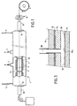
- la figure 1 est une vue très schématique d'une partie d'installation de carbonisation en continu de tissu ;
- la figure 2 est une vue en coupe longitudinale d'un mode de réalisation conforme à l'invention d'une boíte d'étanchéité du four de l'installation de la figure 1 ;
- la figure 3 est une vue partielle en coupe transversale selon le plan III-III de la figure 2 ;
- la figure 4 est une vue partielle d'un tissu décadré ; et
- la figure 5 est une vue très schématique en coupe transversale d'une variante de réalisation d'un joint gonflable dans une boíte d'étanchéité conforme à l'invention.
Claims (13)
- Boíte d'étanchéité pour une enceinte dans une installation de traitement en continu de produit en bande, comprenant :caractérisée en ce que :un passage longitudinal (12) s'ouvrant à une première extrémité de la boíte destinée à être raccordée à une entrée ou sortie de l'enceinte (1), et à une deuxième extrémité opposée à la première,une surface de support (14a) à l'intérieur du passage, sur laquelle peut défiler un produit en bande (T) entre les extrémités de la boíte, etdes moyens d'étanchéité statiques (30) comportant au moins un joint gonflable (32) disposé transversalement dans le passage (12), au-dessus de la surface de support (14a), et agissant par contact avec un produit en bande défilant dans le passage sur la surface de support,des moyens d'étanchéité dynamiques (40) sont en outre prévus dans le passage, entre la deuxième extrémité de la boíte et les moyens d'étanchéité statiques, et comportent des moyens (52, 56) d'injection de gaz dans au moins une chambre (42, 46) formée dans le passage.
- Boíte d'étanchéité selon la revendication 1, caractérisée en ce que le joint gonflable (32) est gonflé à une pression excédant la pression atmosphérique de moins de 500 Pa.
- Boíte d'étanchéité selon l'une quelconque des revendications 1 et 2, caractérisée en ce que le joint gonflable (32) est relié à une conduite d'alimentation en gaz (38).
- Boíte d'étanchéité selon l'une quelconque des revendications 1 à 3, caractérisée en ce qu'elle comporte des moyens (56) d'injection de gaz dans une chambre (46) délimitée par le joint gonflable (32) et une paroi (66) disposée transversalement dans le passage.
- Boíte d'étanchéité selon l'une quelconque des revendications 1 à 4, caractérisée en ce que les moyens d'étanchéité dynamiques comportent plusieurs chambres adjacentes (42, 44, 46) séparées les unes des autres par des parois (62, 64, 66) disposées transversalement dans le passage, chaque chambre étant munie d'une ouverture d'injection ou d'extraction de gaz.
- Boíte d'étanchéité selon la revendication 5, caractérisée en ce qu'elle comporte au moins une chambre d'extraction (44) située entre deux chambres d'injection (42, 46).
- Boíte d'étanchéité selon l'une quelconque des revendications 4, 5 et 6, caractérisée en ce que la ou chaque paroi (62, 64, 66) délimitant une chambre est munie d'une bavette souple (72, 74, 76) à son extrémité adjacente au trajet d'un tissu dans le passage (12).
- Boíte d'étanchéité selon l'une quelconque des revendications 1 à 7, caractérisée en ce qu'au moins un écran thermique (80) est interposé entre le joint gonflable (32) et la première extrémité de la boíte.
- Boíte d'étanchéité selon l'une quelconque des revendications 1 à 8, caractérisée en ce qu'elle comporte une embase (14), formant ladite surface de support (14a) et un couvercle (16) délimitant ledit passage (12).
- Boíte d'étanchéité selon la revendication 9, caractérisée en ce que le couvercle (16) est articulé par rapport à l'embase (14).
- Boíte d'étanchéité selon l'une quelconque des revendications 1 à 10, caractérisée en ce que le joint souple gonflable est formé de plusieurs sections adjacentes (1321, ..., 1326) alignées en direction transversale dans le passage, chaque section étant munie de moyens de gonflage particuliers (1381, ..., 1386) afin de pouvoir régler de façon indépendante la pression de gonflage dans chaque section de joint.
- Procédé de contrôle du droit fil d'un tissu en fibres de carbone issu d'un four d'une installation de carbonisation en continu munie, en entrée du four, d'une boíte d'étanchéité selon la revendication 11, caractérisé en ce que les pressions de gonflage des sections du joint souple sont commandées sélectivement en fonction d'un décadrage éventuel du tissu.
- Installation de carbonisation en continu d'un substrat fibreux en bande comprenant un four muni, au moins en entrée, d'une boíte d'étanchéité selon l'une quelconque des revendications 1 à 11.
Applications Claiming Priority (3)
| Application Number | Priority Date | Filing Date | Title |
|---|---|---|---|
| FR9915332A FR2801953B1 (fr) | 1999-12-06 | 1999-12-06 | Boite d'etancheite pour une enceinte de traitement en continu de produit mince en bande, notamment pour four de carbonisation en continu de substrat fibreux |
| FR9915332 | 1999-12-06 | ||
| PCT/FR2000/003386 WO2001042542A1 (fr) | 1999-12-06 | 2000-12-05 | Boite d'etancheite pour une enceinte de traitement en continu de produit mince en bande |
Publications (2)
| Publication Number | Publication Date |
|---|---|
| EP1240367A1 EP1240367A1 (fr) | 2002-09-18 |
| EP1240367B1 true EP1240367B1 (fr) | 2004-05-26 |
Family
ID=9552917
Family Applications (1)
| Application Number | Title | Priority Date | Filing Date |
|---|---|---|---|
| EP00985405A Expired - Lifetime EP1240367B1 (fr) | 1999-12-06 | 2000-12-05 | Boite d'etancheite pour une enceinte de traitement en continu de produit mince en bande |
Country Status (12)
| Country | Link |
|---|---|
| US (1) | US6561799B2 (fr) |
| EP (1) | EP1240367B1 (fr) |
| JP (1) | JP4741137B2 (fr) |
| AT (1) | ATE267899T1 (fr) |
| AU (1) | AU2183201A (fr) |
| BR (1) | BR0016122B1 (fr) |
| DE (1) | DE60011136T2 (fr) |
| FR (1) | FR2801953B1 (fr) |
| MX (1) | MXPA02005627A (fr) |
| RU (1) | RU2249635C2 (fr) |
| UA (1) | UA73534C2 (fr) |
| WO (1) | WO2001042542A1 (fr) |
Families Citing this family (18)
| Publication number | Priority date | Publication date | Assignee | Title |
|---|---|---|---|---|
| EP2013396A1 (fr) | 2006-05-02 | 2009-01-14 | Dow Corning Ireland Limited | Système de remplacement de fluides |
| JP4977754B2 (ja) * | 2006-05-02 | 2012-07-18 | ダウ・コーニング・アイルランド・リミテッド | ウェブシール装置 |
| RU2506356C1 (ru) * | 2012-07-13 | 2014-02-10 | Открытое акционерное общество "Научно-исследовательский институт конструкционных материалов на основе графита "НИИграфит" | Установка карбонизации волокнистых вискозных материалов для получения комбинированных углеродных нитей |
| US9362546B1 (en) | 2013-01-07 | 2016-06-07 | Quantumscape Corporation | Thin film lithium conducting powder material deposition from flux |
| US10403931B2 (en) | 2013-10-07 | 2019-09-03 | Quantumscape Corporation | Garnet materials for Li secondary batteries and methods of making and using garnet materials |
| CN103820134B (zh) * | 2014-02-26 | 2015-06-10 | 北京北方永邦科技股份有限公司 | 一种密封出料方法和连续式密封出料装置 |
| CN104531170B (zh) * | 2014-12-24 | 2017-06-20 | 湖南顶立科技有限公司 | 一种连续式碳化设备及其进出料密封装置 |
| KR20240059640A (ko) | 2015-04-16 | 2024-05-07 | 퀀텀스케이프 배터리, 인코포레이티드 | 고체 전해질 제조를 위한 리튬 함유 가넷 세터 플레이트 |
| JP2018528916A (ja) | 2015-07-21 | 2018-10-04 | クアンタムスケイプ コーポレイション | グリーンガーネット薄膜を流延及び焼結するプロセス及び材料 |
| US9966630B2 (en) | 2016-01-27 | 2018-05-08 | Quantumscape Corporation | Annealed garnet electrolyte separators |
| RU2636541C1 (ru) * | 2016-07-28 | 2017-11-23 | Общество с ограниченной ответственностью Научно-производственный центр "УВИКОМ" | Герметизирующий затвор к проходной печи для непрерывной термической обработки химического волокна при изготовлении углеродного волокнистого материала |
| US11158880B2 (en) | 2016-08-05 | 2021-10-26 | Quantumscape Battery, Inc. | Translucent and transparent separators |
| US11916200B2 (en) | 2016-10-21 | 2024-02-27 | Quantumscape Battery, Inc. | Lithium-stuffed garnet electrolytes with a reduced surface defect density and methods of making and using the same |
| RU2636776C1 (ru) * | 2017-03-13 | 2017-11-28 | Общество с ограниченной ответственностью Научно-производственный центр "УВИКОМ" | Герметизирующий затвор к печи для непрерывной термической обработки волокнистого углеродного материала |
| WO2018236394A1 (fr) | 2017-06-23 | 2018-12-27 | Quantumscape Corporation | Électrolytes de grenat remplis de lithium avec des inclusions de phase secondaire |
| WO2019090360A1 (fr) | 2017-11-06 | 2019-05-09 | Quantumscape Corporation | Films minces de grenat remplis de lithium et pastilles présentant une surface oxyfluorée et/ou fluorée et procédés de fabrication et d'utilisation des films minces et des pastilles |
| US12469876B2 (en) | 2020-01-15 | 2025-11-11 | Quantumscape Battery, Inc. | High green density ceramics for battery |
| CN114518030A (zh) * | 2022-03-21 | 2022-05-20 | 咸阳科源陶瓷有限公司 | 一种回转炉动静结合式密封装置 |
Family Cites Families (15)
| Publication number | Priority date | Publication date | Assignee | Title |
|---|---|---|---|---|
| US2199521A (en) * | 1937-08-21 | 1940-05-07 | Doderer Wilhelm | Contrivance for treating materials within a gas atmosphere of increased pressure |
| US2977106A (en) * | 1957-05-08 | 1961-03-28 | Selas Corp Of America | Furnace closure |
| US3704872A (en) * | 1968-08-21 | 1972-12-05 | Mallory & Co Inc P R | Sintering furnace |
| GB1479886A (en) * | 1974-06-14 | 1977-07-13 | Holliday & Co Ltd L | Printing textile fabrics or filaments |
| JPS57117624A (en) * | 1981-01-13 | 1982-07-22 | Mitsubishi Rayon Co Ltd | Gas-sealing method in baking furnace |
| DE3277843D1 (en) * | 1981-09-19 | 1988-01-28 | British Oxygen Co Ltd | Heat treatment of metals |
| US5193996A (en) * | 1983-10-13 | 1993-03-16 | Bp Chemicals (Hitco) Inc. | Method and system for producing carbon fibers |
| JPS60224713A (ja) * | 1984-04-23 | 1985-11-09 | Daido Steel Co Ltd | ガスシ−ル装置 |
| DE3430205C1 (de) * | 1984-08-17 | 1986-03-27 | Otto Junker Gmbh, 5107 Simmerath | Schleuse fuer Gluehofenanlagen |
| JPS6226482A (ja) * | 1985-07-26 | 1987-02-04 | 石川島播磨重工業株式会社 | 熱処理炉のガスシ−ル装置 |
| DE3791032T1 (de) * | 1987-11-26 | 1990-03-15 | Valmet Oy | Verfahren und vorrichtung zur streichmassentrocknung einer papierbahn oder dergleichen in der maschine |
| RU2005829C1 (ru) | 1992-08-04 | 1994-01-15 | Казаков Марк Евгеньевич | Агрегат тепловой обработки волокнистого материала |
| RU2047674C1 (ru) | 1993-07-09 | 1995-11-10 | Алентин Михайлович Трушников | Способ получения углеродного волокнистого материала |
| FR2741363B1 (fr) * | 1995-11-17 | 1998-02-20 | Carbone Ind | Procede et four d'activation d'une nappe textile tissee ou non tissee a base de fils continus ou de fils de fibres carbonees |
| DE19846749C2 (de) * | 1998-10-12 | 2000-10-12 | Junker Gmbh O | Aerodynamische Abdichtung von Durchlauf-Wärmebehandlungsanlagen mit Schutzgasatmosphäre |
-
1999
- 1999-12-06 FR FR9915332A patent/FR2801953B1/fr not_active Expired - Fee Related
-
2000
- 2000-05-12 UA UA2002064659A patent/UA73534C2/uk unknown
- 2000-12-05 RU RU2002115276/12A patent/RU2249635C2/ru not_active IP Right Cessation
- 2000-12-05 AU AU21832/01A patent/AU2183201A/en not_active Abandoned
- 2000-12-05 BR BRPI0016122-5A patent/BR0016122B1/pt not_active IP Right Cessation
- 2000-12-05 DE DE60011136T patent/DE60011136T2/de not_active Expired - Lifetime
- 2000-12-05 MX MXPA02005627A patent/MXPA02005627A/es active IP Right Grant
- 2000-12-05 WO PCT/FR2000/003386 patent/WO2001042542A1/fr not_active Ceased
- 2000-12-05 JP JP2001544408A patent/JP4741137B2/ja not_active Expired - Fee Related
- 2000-12-05 EP EP00985405A patent/EP1240367B1/fr not_active Expired - Lifetime
- 2000-12-05 AT AT00985405T patent/ATE267899T1/de active
- 2000-12-05 US US10/149,159 patent/US6561799B2/en not_active Expired - Lifetime
Also Published As
| Publication number | Publication date |
|---|---|
| WO2001042542A1 (fr) | 2001-06-14 |
| MXPA02005627A (es) | 2004-09-10 |
| RU2249635C2 (ru) | 2005-04-10 |
| US20020182556A1 (en) | 2002-12-05 |
| EP1240367A1 (fr) | 2002-09-18 |
| FR2801953B1 (fr) | 2002-05-10 |
| JP4741137B2 (ja) | 2011-08-03 |
| DE60011136T2 (de) | 2005-06-16 |
| ATE267899T1 (de) | 2004-06-15 |
| UA73534C2 (en) | 2005-08-15 |
| AU2183201A (en) | 2001-06-18 |
| US6561799B2 (en) | 2003-05-13 |
| BR0016122B1 (pt) | 2011-08-09 |
| BR0016122A (pt) | 2002-08-06 |
| RU2002115276A (ru) | 2004-01-20 |
| FR2801953A1 (fr) | 2001-06-08 |
| DE60011136D1 (de) | 2004-07-01 |
| JP2003516515A (ja) | 2003-05-13 |
Similar Documents
| Publication | Publication Date | Title |
|---|---|---|
| EP1240367A1 (fr) | Boite d'etancheite pour une enceinte de traitement en continu de produit mince en bande | |
| BE1008560A3 (fr) | Dispositif et procede pour former un revetement par pyrolyse. | |
| FR2644182A1 (fr) | Rouleau de renvoi pour bande poreuse, notamment pour toile de sechage dans une machine a papier | |
| FR2732042A1 (fr) | Cylindre aspirant permettant le transfert d'un voile fibreux entre un tapis de transport et deux cylindres de calandrage | |
| FR2511054A1 (fr) | Tissu a trois couches pour la formation de feuilles, en particulier de feuilles de papier sur une machine a papier a deux toiles | |
| FR2725216A1 (fr) | Dispositif pour detacher et transporter a grande vitesse un voile fibreux en sortie de carde | |
| CH681804A5 (fr) | ||
| FR2741363A1 (fr) | Procede et four d'activation d'une nappe textile tissee ou non tissee a base de fils continus ou de fils de fibres carbonees | |
| EP1004369B2 (fr) | Sas d'étanchéité pour chambre à vide | |
| EP1348039B1 (fr) | Installation dans laquelle est realisee une operation necessitant un contr le de l'atmosphere a l'interieur d'une enceinte | |
| EP1627096B1 (fr) | Sas d'etancheite pour ligne de depot sous vide sur produit plat | |
| EP1160342A1 (fr) | Procédé de mise en sécurisation d'une enceinte de traitement thermique fonctionnant sous atmosphère contrôlée | |
| BE1008433A3 (fr) | Dispositif de fabrication d'un matelas de fibres. | |
| EP1179096A2 (fr) | Procede pour l'obtention de tissu en fibres de carbone par carbonisation en continu d'un tissu en fibres cellulosiques | |
| FR2549452A1 (fr) | Sas a vide avec des porte-objets pour introduire des objets dans des enceintes a vide et les faire sortir de celles-ci | |
| FR2672519A1 (fr) | Buse a talon aval sureleve, pour deposer une couche de revetement sur un ruban de verre, par pyrolyse d'un melange gazeux. | |
| FR2546810A1 (fr) | Procede et dispositif pour la fabrication de feuilles de matiere plastique de bonne qualite optique, par coulee | |
| FR2893531A1 (fr) | Procede de consolidation en continu pour l'obtention d'un materiau stratifie et dispositif pour sa mise en oeuvre | |
| FR2670514A1 (fr) | Procede et dispositif pour compenser le flechissement d'une poutre de support de racle. | |
| CA2115493A1 (fr) | Dispositif de distribution de solides pulverulents a la surface d'un substrat afin de le revetir | |
| EP2507400B1 (fr) | Dispositif pour maintenir seche l'atmosphere d'un four de recuit pour bande metallique, et four equipe de ce dispositif. | |
| FR2757790A1 (fr) | Procede de coulee continue de bandes metalliques minces entre deux cylindres, et installation pour sa mise en oeuvre | |
| EP0937956A1 (fr) | Dispositif pour le traitement thermique de matériaux en feuille défilant en continu | |
| CA1038674A (fr) | Fabrication de nappes uniformes a partir de materiaux particulaires | |
| WO2002070381A1 (fr) | Procede de transport d'articles legers et convoyeur a air pour la mise en oeuvre de ce procede |
Legal Events
| Date | Code | Title | Description |
|---|---|---|---|
| PUAI | Public reference made under article 153(3) epc to a published international application that has entered the european phase |
Free format text: ORIGINAL CODE: 0009012 |
|
| 17P | Request for examination filed |
Effective date: 20020704 |
|
| AK | Designated contracting states |
Kind code of ref document: A1 Designated state(s): AT BE CH CY DE DK ES FI FR GB GR IE IT LI LU MC NL |
|
| AX | Request for extension of the european patent |
Free format text: AL;LT;LV;MK;RO;SI |
|
| RAP1 | Party data changed (applicant data changed or rights of an application transferred) |
Owner name: SNECMA PROPULSION SOLIDE |
|
| 17Q | First examination report despatched |
Effective date: 20030620 |
|
| GRAP | Despatch of communication of intention to grant a patent |
Free format text: ORIGINAL CODE: EPIDOSNIGR1 |
|
| GRAS | Grant fee paid |
Free format text: ORIGINAL CODE: EPIDOSNIGR3 |
|
| GRAA | (expected) grant |
Free format text: ORIGINAL CODE: 0009210 |
|
| AK | Designated contracting states |
Kind code of ref document: B1 Designated state(s): AT DE FR GB IT |
|
| REG | Reference to a national code |
Ref country code: GB Ref legal event code: FG4D Free format text: NOT ENGLISH |
|
| REG | Reference to a national code |
Ref country code: IE Ref legal event code: FG4D Free format text: FRENCH |
|
| REF | Corresponds to: |
Ref document number: 60011136 Country of ref document: DE Date of ref document: 20040701 Kind code of ref document: P |
|
| GBT | Gb: translation of ep patent filed (gb section 77(6)(a)/1977) |
Effective date: 20040831 |
|
| LTIE | Lt: invalidation of european patent or patent extension |
Effective date: 20040526 |
|
| REG | Reference to a national code |
Ref country code: IE Ref legal event code: FD4D |
|
| PLBE | No opposition filed within time limit |
Free format text: ORIGINAL CODE: 0009261 |
|
| STAA | Information on the status of an ep patent application or granted ep patent |
Free format text: STATUS: NO OPPOSITION FILED WITHIN TIME LIMIT |
|
| 26N | No opposition filed |
Effective date: 20050301 |
|
| REG | Reference to a national code |
Ref country code: DE Ref legal event code: R082 Ref document number: 60011136 Country of ref document: DE Representative=s name: CBDL PATENTANWAELTE, DE |
|
| REG | Reference to a national code |
Ref country code: DE Ref legal event code: R082 Ref document number: 60011136 Country of ref document: DE Representative=s name: CBDL PATENTANWAELTE, DE Effective date: 20130114 Ref country code: DE Ref legal event code: R081 Ref document number: 60011136 Country of ref document: DE Owner name: HERAKLES, FR Free format text: FORMER OWNER: SNECMA PROPULSION SOLIDE S.A., LE HAILLAN CEDEX, FR Effective date: 20130114 |
|
| REG | Reference to a national code |
Ref country code: GB Ref legal event code: 732E Free format text: REGISTERED BETWEEN 20130221 AND 20130227 |
|
| REG | Reference to a national code |
Ref country code: FR Ref legal event code: TP Owner name: HERAKLES, FR Effective date: 20130513 |
|
| REG | Reference to a national code |
Ref country code: AT Ref legal event code: PC Ref document number: 267899 Country of ref document: AT Kind code of ref document: T Owner name: HERAKLES, FR Effective date: 20140311 |
|
| REG | Reference to a national code |
Ref country code: FR Ref legal event code: PLFP Year of fee payment: 16 |
|
| REG | Reference to a national code |
Ref country code: FR Ref legal event code: PLFP Year of fee payment: 17 |
|
| PGFP | Annual fee paid to national office [announced via postgrant information from national office to epo] |
Ref country code: DE Payment date: 20161121 Year of fee payment: 17 Ref country code: GB Payment date: 20161128 Year of fee payment: 17 |
|
| PGFP | Annual fee paid to national office [announced via postgrant information from national office to epo] |
Ref country code: AT Payment date: 20161122 Year of fee payment: 17 Ref country code: IT Payment date: 20161125 Year of fee payment: 17 |
|
| REG | Reference to a national code |
Ref country code: FR Ref legal event code: PLFP Year of fee payment: 18 |
|
| REG | Reference to a national code |
Ref country code: DE Ref legal event code: R119 Ref document number: 60011136 Country of ref document: DE |
|
| REG | Reference to a national code |
Ref country code: AT Ref legal event code: MM01 Ref document number: 267899 Country of ref document: AT Kind code of ref document: T Effective date: 20171205 |
|
| GBPC | Gb: european patent ceased through non-payment of renewal fee |
Effective date: 20171205 |
|
| PG25 | Lapsed in a contracting state [announced via postgrant information from national office to epo] |
Ref country code: DE Free format text: LAPSE BECAUSE OF NON-PAYMENT OF DUE FEES Effective date: 20180703 Ref country code: IT Free format text: LAPSE BECAUSE OF NON-PAYMENT OF DUE FEES Effective date: 20171205 |
|
| PG25 | Lapsed in a contracting state [announced via postgrant information from national office to epo] |
Ref country code: AT Free format text: LAPSE BECAUSE OF NON-PAYMENT OF DUE FEES Effective date: 20171205 Ref country code: GB Free format text: LAPSE BECAUSE OF NON-PAYMENT OF DUE FEES Effective date: 20171205 |
|
| PGFP | Annual fee paid to national office [announced via postgrant information from national office to epo] |
Ref country code: FR Payment date: 20181220 Year of fee payment: 19 |
|
| PG25 | Lapsed in a contracting state [announced via postgrant information from national office to epo] |
Ref country code: FR Free format text: LAPSE BECAUSE OF NON-PAYMENT OF DUE FEES Effective date: 20191231 |