EP1239362A2 - Verfahren und Einrichtung zum Steuern einer Anzeigetafel, Armbanduhr-Informationseinrichtung, und tragbares Gerät - Google Patents
Verfahren und Einrichtung zum Steuern einer Anzeigetafel, Armbanduhr-Informationseinrichtung, und tragbares Gerät Download PDFInfo
- Publication number
- EP1239362A2 EP1239362A2 EP02251270A EP02251270A EP1239362A2 EP 1239362 A2 EP1239362 A2 EP 1239362A2 EP 02251270 A EP02251270 A EP 02251270A EP 02251270 A EP02251270 A EP 02251270A EP 1239362 A2 EP1239362 A2 EP 1239362A2
- Authority
- EP
- European Patent Office
- Prior art keywords
- driving
- panel
- organic
- voltage
- liquid
- Prior art date
- Legal status (The legal status is an assumption and is not a legal conclusion. Google has not performed a legal analysis and makes no representation as to the accuracy of the status listed.)
- Granted
Links
Images


Classifications
-
- G—PHYSICS
- G06—COMPUTING OR CALCULATING; COUNTING
- G06F—ELECTRIC DIGITAL DATA PROCESSING
- G06F3/00—Input arrangements for transferring data to be processed into a form capable of being handled by the computer; Output arrangements for transferring data from processing unit to output unit, e.g. interface arrangements
- G06F3/14—Digital output to display device ; Cooperation and interconnection of the display device with other functional units
- G06F3/147—Digital output to display device ; Cooperation and interconnection of the display device with other functional units using display panels
-
- G—PHYSICS
- G09—EDUCATION; CRYPTOGRAPHY; DISPLAY; ADVERTISING; SEALS
- G09G—ARRANGEMENTS OR CIRCUITS FOR CONTROL OF INDICATING DEVICES USING STATIC MEANS TO PRESENT VARIABLE INFORMATION
- G09G3/00—Control arrangements or circuits, of interest only in connection with visual indicators other than cathode-ray tubes
- G09G3/04—Control arrangements or circuits, of interest only in connection with visual indicators other than cathode-ray tubes for presentation of a single character by selection from a plurality of characters, or by composing the character by combination of individual elements, e.g. segments using a combination of such display devices for composing words, rows or the like, in a frame with fixed character positions
- G09G3/06—Control arrangements or circuits, of interest only in connection with visual indicators other than cathode-ray tubes for presentation of a single character by selection from a plurality of characters, or by composing the character by combination of individual elements, e.g. segments using a combination of such display devices for composing words, rows or the like, in a frame with fixed character positions using controlled light sources
- G09G3/12—Control arrangements or circuits, of interest only in connection with visual indicators other than cathode-ray tubes for presentation of a single character by selection from a plurality of characters, or by composing the character by combination of individual elements, e.g. segments using a combination of such display devices for composing words, rows or the like, in a frame with fixed character positions using controlled light sources using electroluminescent elements
- G09G3/14—Semiconductor devices, e.g. diodes
-
- G—PHYSICS
- G09—EDUCATION; CRYPTOGRAPHY; DISPLAY; ADVERTISING; SEALS
- G09G—ARRANGEMENTS OR CIRCUITS FOR CONTROL OF INDICATING DEVICES USING STATIC MEANS TO PRESENT VARIABLE INFORMATION
- G09G3/00—Control arrangements or circuits, of interest only in connection with visual indicators other than cathode-ray tubes
- G09G3/04—Control arrangements or circuits, of interest only in connection with visual indicators other than cathode-ray tubes for presentation of a single character by selection from a plurality of characters, or by composing the character by combination of individual elements, e.g. segments using a combination of such display devices for composing words, rows or the like, in a frame with fixed character positions
- G09G3/16—Control arrangements or circuits, of interest only in connection with visual indicators other than cathode-ray tubes for presentation of a single character by selection from a plurality of characters, or by composing the character by combination of individual elements, e.g. segments using a combination of such display devices for composing words, rows or the like, in a frame with fixed character positions by control of light from an independent source
- G09G3/18—Control arrangements or circuits, of interest only in connection with visual indicators other than cathode-ray tubes for presentation of a single character by selection from a plurality of characters, or by composing the character by combination of individual elements, e.g. segments using a combination of such display devices for composing words, rows or the like, in a frame with fixed character positions by control of light from an independent source using liquid crystals
-
- G—PHYSICS
- G06—COMPUTING OR CALCULATING; COUNTING
- G06F—ELECTRIC DIGITAL DATA PROCESSING
- G06F3/00—Input arrangements for transferring data to be processed into a form capable of being handled by the computer; Output arrangements for transferring data from processing unit to output unit, e.g. interface arrangements
- G06F3/14—Digital output to display device ; Cooperation and interconnection of the display device with other functional units
- G06F3/1423—Digital output to display device ; Cooperation and interconnection of the display device with other functional units controlling a plurality of local displays, e.g. CRT and flat panel display
-
- G—PHYSICS
- G09—EDUCATION; CRYPTOGRAPHY; DISPLAY; ADVERTISING; SEALS
- G09G—ARRANGEMENTS OR CIRCUITS FOR CONTROL OF INDICATING DEVICES USING STATIC MEANS TO PRESENT VARIABLE INFORMATION
- G09G2300/00—Aspects of the constitution of display devices
- G09G2300/02—Composition of display devices
- G09G2300/023—Display panel composed of stacked panels
-
- G—PHYSICS
- G09—EDUCATION; CRYPTOGRAPHY; DISPLAY; ADVERTISING; SEALS
- G09G—ARRANGEMENTS OR CIRCUITS FOR CONTROL OF INDICATING DEVICES USING STATIC MEANS TO PRESENT VARIABLE INFORMATION
- G09G2310/00—Command of the display device
- G09G2310/02—Addressing, scanning or driving the display screen or processing steps related thereto
- G09G2310/0264—Details of driving circuits
- G09G2310/0278—Details of driving circuits arranged to drive both scan and data electrodes
-
- G—PHYSICS
- G09—EDUCATION; CRYPTOGRAPHY; DISPLAY; ADVERTISING; SEALS
- G09G—ARRANGEMENTS OR CIRCUITS FOR CONTROL OF INDICATING DEVICES USING STATIC MEANS TO PRESENT VARIABLE INFORMATION
- G09G2320/00—Control of display operating conditions
- G09G2320/02—Improving the quality of display appearance
- G09G2320/0247—Flicker reduction other than flicker reduction circuits used for single beam cathode-ray tubes
-
- G—PHYSICS
- G09—EDUCATION; CRYPTOGRAPHY; DISPLAY; ADVERTISING; SEALS
- G09G—ARRANGEMENTS OR CIRCUITS FOR CONTROL OF INDICATING DEVICES USING STATIC MEANS TO PRESENT VARIABLE INFORMATION
- G09G2330/00—Aspects of power supply; Aspects of display protection and defect management
- G09G2330/02—Details of power systems and of start or stop of display operation
- G09G2330/028—Generation of voltages supplied to electrode drivers in a matrix display other than LCD
-
- G—PHYSICS
- G09—EDUCATION; CRYPTOGRAPHY; DISPLAY; ADVERTISING; SEALS
- G09G—ARRANGEMENTS OR CIRCUITS FOR CONTROL OF INDICATING DEVICES USING STATIC MEANS TO PRESENT VARIABLE INFORMATION
- G09G3/00—Control arrangements or circuits, of interest only in connection with visual indicators other than cathode-ray tubes
- G09G3/04—Control arrangements or circuits, of interest only in connection with visual indicators other than cathode-ray tubes for presentation of a single character by selection from a plurality of characters, or by composing the character by combination of individual elements, e.g. segments using a combination of such display devices for composing words, rows or the like, in a frame with fixed character positions
Definitions
- the present invention relates to a panel driving control device for driving a liquid-crystal panel and an organic EL panel, a wristwatch-type information device and a portable device having this panel driving control device, and a panel driving control method for driving a liquid-crystal panel and an organic EL panel.
- LCDs Liquid-crystal panels
- organic EL Electro Luminescence
- the organic EL panel does not have a characteristic dependent on the viewing angle unlike an LCD, and has attracted attention as a next-generation display suitable for, in particular, portable devices, such as wristwatches or portable phones.
- organic EL panels have a problem in that the power consumption (in particular, the current consumption) is large, and reduction thereof is considered to be a technical challenge in the future.
- the power consumption in particular, the current consumption
- the current consumption of organic EL panels is approximately 1 mA. That is, organic EL panels require a current consumption approximately 1,000 times larger than that of LCDs of the same size.
- an AC voltage is applied thereto in order to drive it.
- a DC voltage is continuously applied to the LCD, a "polarization" phenomenon occurs, and the performance deteriorates.
- a method of driving the LCD in the case of, for example, a digital watch, a method is adopted in which an AC waveform having a frame frequency of approximately 25 to 60 Hz is used.
- a DC voltage is applied thereto in order to drive it.
- the organic EL panel has a characteristic of emitting light as a result of causing an electrical current to continuously flow in a fixed direction. Due to such a difference in driving methods, a dedicated driver capable of applying an AC voltage is used for the LCD, whereas a dedicated driver capable of applying a DC voltage is used for the organic EL panel.
- An object of the present invention is to provide a panel driving control device, a wristwatch-type information device, a portable device, and a panel driving control method which are capable of driving an LCD and an organic EL panel without providing individual dedicated drivers for these two panels.
- a panel driving control device comprising:
- the second construction of the present invention is such that, in the first construction, the driving frequency supplied from the frequency supply means is approximately twice the driving frequency which is normally required for the liquid-crystal panel to be driven.
- a third construction of the present invention is such that, in the first construction, the driving frequency supplied by the frequency supply means is a frequency which is equal to or higher than 50 Hz.
- a fourth construction of the present invention comprises:
- a fifth construction of the present invention is such that, in the fourth construction, the driving voltage supplied by the common driving method and the voltage supply means is determined by the single color displayed on the organic EL panel.
- a sixth construction of the present invention comprises:
- a driving voltage and a driving method for driving the liquid-crystal panel and the organic EL panel are selected according to the display color displayed by the organic EL panel.
- the selected driving method is reported to the liquid-crystal panel control means and the organic-EL-panel control means, and the selected driving voltage is supplied to the liquid-crystal panel control means and the organic-EL-panel control means.
- the liquid-crystal panel control means and the organic-EL-panel control means control panel driving in accordance with the reported driving method on the basis of the supplied driving voltage.
- a seventh construction of the present invention is such that, in the sixth construction, the driving method selection means selects a driving voltage suitable for driving a display color displayed by the organic EL panel from among a plurality of driving voltages of different magnitudes, and selects a driving method of a duty ratio suitable for driving a display color to be displayed by the organic EL panel from among a plurality of driving methods of different duty ratios.
- An eighth construction of the present invention is a wristwatch-type information device having mounted therein:
- a ninth construction of the present invention is a portable device having mounted therein:
- a tenth construction of the present invention comprises:
- An eleventh construction of the present invention is such that, in the tenth construction, the driving frequency supplied in the frequency supply step is approximately twice the driving frequency which is normally required for the liquid-crystal panel to be driven.
- a twelfth construction of the present invention is such that, in the tenth construction, the driving frequency supplied in the frequency supply step is a frequency which is equal to or higher than 50 Hz.
- a thirteenth construction of the present invention comprises:
- a fourteenth construction of the present invention is such that, in the thirteenth construction, the driving voltage supplied in the common driving method and the voltage supply step is determined by the single color displayed on the organic EL panel.
- a fifteenth construction of the present invention comprises:
- a sixteenth construction of the present invention is such that, in the fifteenth construction, the driving method selection step selects a driving voltage suitable for driving a display color displayed by the organic EL panel from among a plurality of driving voltages of different magnitudes, and selects a driving method of a duty ratio suitable for driving a display color to be displayed by the organic EL panel from among a plurality of driving methods of different duty ratios.
- Fig. 1 is a plan view when a wristwatch-type information device 100 according to the embodiment is viewed from the obverse-surface side.
- Fig. 2 is a sectional view of the wristwatch-type information device 100 when it is viewed from the AA' direction in Fig. 1.
- a display section 110 of this wristwatch-type information device 100 As shown in Fig. 1(A), on a display section 110 of this wristwatch-type information device 100, the date, the day of the week, and the time are always displayed. In the example shown in Fig. 1(A), it is shown that the current time is December 8 (Friday), 13:45. Information which is always displayed on the display section 110 in this manner is hereinafter referred to as "always displayed information". This always displayed information is displayed by a liquid-crystal display (hereinafter referred to as an "LCD”) which forms the display section 110.
- LCD liquid-crystal display
- This wristwatch-type information device 100 has a schedule management function for performing user schedule management, so that, for a predetermined period before the schedule starts (for example, for a period of 10 seconds 5 minutes before the schedule starts), as shown in Fig. 1(B), a message informing the user that there is a schedule is displayed.
- a predetermined period before the schedule starts for example, for a period of 10 seconds 5 minutes before the schedule starts
- a message informing the user that there is a schedule is displayed.
- Fig. 1(B) Information which is displayed only for a predetermined period on the display section 110 in this manner is hereinafter referred to as "limited display information".
- This limited display information is displayed by a transparent organic EL panel which forms the display section 110.
- the limited display information is displayed in a state overlapping with the always displayed information which is displayed as in Fig. 1(A). That is, when viewed by the user, the limited display information is displayed in the foreground, and the always displayed information is displayed in the background.
- the wristwatch-type information device 100 is constructed in such a way that a circuit board 4 is provided inside a housing formed of a cover glass 1, a case 2, and a rear lid 6.
- a quartz oscillator 5 for generating a source oscillation signal having a reference frequency, and a battery 109 for supplying power to each section of the wristwatch-type information device 100 are provided.
- an IC chip 3 for controlling various control processes (to be described later) is provided, an LCD 112 is provided above the IC chip 3 at a position spaced therefrom, and an organic EL panel 111 is provided further above the LCD.
- the organic EL panel 111 is constructed as a transparent panel in which, from the side opposing the cover glass 1, a transparent glass, a transparent anode material, a hole transportation layer, an organic light-emitting layer, an electron transportation layer, and a cathode material (none is shown) are laminated in this order.
- the transparent electrode is a transparent material, such as ITO, having conductivity
- the cathode material is formed by a metallic thin-film having a low work function, such as, for example, calcium, magnesium, aluminum, etc.
- Another transparent material can be used instead for the transparent glass, such as transparent plastic, and a flexible material can also be used.
- the organic EL panel positioned above the LCD 112 as described above is transparent, when viewed by the user, in the state in which nothing is displayed on the organic EL panel 111, it is possible to see the display of the LCD 112 which is under the organic EL panel 111 without the field of view being obstructed by the organic EL panel 111. Furthermore, even in the state in which information is displayed on the organic EL panel 111, not all the displayed contents of the LCD 112 are seen, and the rough contents thereof can be seen.
- the display area of the organic EL panel 111 is divided into three areas in advance according to the display colors thereof.
- Fig. 3 is a plan view when the organic EL panel is viewed from the obverse-surface side (the side opposing the cover glass 1).
- the display area of the organic EL panel 111 is divided into a blue display area 111b for displaying blue, a red display area 111r for displaying red, and a green display area 111g for displaying green, from the upper portion of the figure (towards the time 12:00) toward the lower portion (towards the time 6:00).
- the display colors of these display areas 111b, 111r and 111g differ depending on the different organic materials used as organic light-emitting layers which form the respective display areas.
- the wristwatch-type information device 1 is so designed that, when limited display information is to be displayed on the organic EL panel 111, one of the these three display areas 111b, 111r and 111g is selected for display. For example, in Fig. 1(B) described above, an example in which a message is displayed on the red display area 111r is shown.
- the wristwatch-type information device 100 has stored therein, in a table form (to be described later), information concerning on which display area the limited display information should be displayed, and performs a display process in accordance with the stored contents.
- the wristwatch-type information device 100 comprises an oscillation circuit 101, a frequency-dividing circuit 102, a CPU (Central Processing Unit) 103, a ROM (Read Only Memory) 104, a RAM (Random Access Memory) 105, an operation input section 106, a panel driver 107, a battery 109, an LCD 112, and an organic EL panel 111.
- a CPU Central Processing Unit
- ROM Read Only Memory
- RAM Random Access Memory
- the oscillation circuit 101 generates a clock signal on the basis of the above-described five oscillation frequencies and outputs it to the frequency-dividing circuit 102.
- the frequency-dividing circuit 102 frequency-divides the clock signal supplied from the oscillation circuit 101, and outputs this signal, as a clock signal for internal processing, to each section of the wristwatch-type information device 100.
- the ROM 104 has various control programs stored therein.
- the CPU 103 reads these control programs and controls each section of the wristwatch-type information device 100. At this time, the RAM 105 is used as a work area for the CPU 103.
- Examples of the control programs stored in the ROM 104 include a schedule management program for storing and outputting schedule information about the schedule of a user, and a character generation program for generating character data for displaying various types of information on the display section 110.
- a schedule management table for recording various types of schedule information input by a user is created in the RAM 105.
- the CPU 103 performs schedule management of the user while referring to this schedule management table.
- the operation input section 106 detects a depressing operation of an operation switch 120 (see Fig. 1) by the user, generates an output signal corresponding to this depressing operation, and outputs it to the CPU 103.
- the panel driver 107 comprises, in addition to a controller (not shown), a driving method control circuit 107b and a driving voltage control circuit 107c.
- This panel driver 107 under the control of the CPU 103, performs driving control of the LCD 112, and at the same time, performs driving control of the organic EL panel 111. That is, in this embodiment, one panel driver 107 functions as a shared driver for driving both the LCD 112 and the organic EL panel 111.
- the controller of the panel driver 107 has a driving method management table 107a stored therein, as shown in Fig. 4. In this driving method management table 107a, the driving voltage and the driving method to be used by the panel driver 107 are described.
- the driving voltage and the driving method are collectively referred to as a "driving method".
- the controller of the panel driver 107 determines an appropriate driving voltage by referring to the driving method management table and instructs the driving voltage control circuit 107c so that the power-supply voltage supplied from the battery 109 is adjusted to the same voltage as the above-described driving voltage. Also, the controller of the panel driver 107 determines an appropriate driving method which should be used by the panel driver 107 by referring to the driving method management table 107a, and reports this method to the driving method control circuit 107b.
- Fig. 5 a description is given of the stored contents of the schedule management table stored in the RAM 105.
- this driving method management table “schedule date”, “schedule time”, “schedule contents”, “display start time”, “display time”, and “display area” in which the schedule contents should be displayed, are provided in such a manner as to correspond to each other. All these pieces of information may be input by the user operating the operation input section 106 of the wristwatch-type information device 1. Alternatively, the display time and the display area may be determined by the CPU 103 executing the schedule management program rather than the user inputting them each time.
- the example of Fig. 5 shows that there is a schedule for a meeting in room 203 from 14:00 on December 8, 2001, and that the schedule contents are displayed in the red display area 111r of the organic EL panel 111 for 10 seconds from 13:55 of the same day.
- the panel driver 107 drives the LCD 112 and the organic EL panel 111 at the same time.
- a driving frequency, a driving voltage, and a driving method when AC driving is performed are selected on the basis of the principles described below, thereby solving the above-described problems.
- Fig. 6(A) is a view showing an example of the assignment of common electrodes and segment electrodes when 1/3-duty multiplex driving is performed with respect to an LCD and an organic EL panel.
- Fig. 6(B) is a corresponding view showing to which of display segments a to g for displaying a character each common electrode and each segment electrode correspond.
- the display segments corresponding to a first common electrode COM0 are shown by hatching
- the display segments corresponding to a second common electrode COM1 are shown by solid lines
- the display segments corresponding to a third common electrode COM2 are shown by oblique lines.
- Fig. 7 shows a waveform of an AC voltage (hereinafter referred to as a "driving waveform") applied to the common electrodes and the segment electrodes of Fig. 6 in a case where a numeral "5" is displayed.
- a reference driving voltage is indicated by 3Vb, and it is shown that, in addition to this driving voltage, the applied voltage levels are 0, Vb, and 2Vb.
- the driving voltage 3Vb is applied only during the period “ta” and the period “td” within the period “ta” to “td” which forms one frame, and the display segment "a” is turned on.
- the display segment "a" in this case may be said to be on/off-controlled at the lowest frequency at which flickering does not occur.
- the display segment "a” emits light repeatedly once in each frame period, that is, at approximately 25 Hz which is the same as the frame frequency. That is, since the frequency of the incident light with respect to the human eye falls below approximately 50 Hz, flickering occurs.
- the driving frequency supplied from the frequency-dividing circuit 102 is set to approximately twice the normal one (25 Hz), that is, approximately 50 Hz.
- the organic EL panel 111 emits light at 50 Hz, which is the same as the driving frequency, flickering does not occur.
- the upper limit of the conventional frame frequency of the LCD is approximately 25 Hz, and the upper limit thereof is approximately 60 Hz. Therefore, the phrase "approximately twice the driving frequency of the LCD" referred to herein refers to "approximately 50 Hz to approximately 120 Hz". However, if the frame frequency of the LCD itself is approximately 50 Hz or higher, even if this frame frequency is used without modification in the organic EL panel, it is estimated that flicker does not occur.
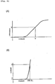
- Fig. 8 shows the relationship between the effective voltage with respect to the LCD and light transmittance. Since it is known that the LCD has cumulative response characteristics such that the LCD is turned on/off in response to the effective value of the voltage which is applied within a predetermined period, here, the effective value of the applied voltage (effective voltage) within one frame period is used as a variable in the X axis in the figure. As shown in Fig. 8, the LCD has characteristics such that the light transmittance varies continuously with respect to the effective voltage.
- a very sharp variation is seen from a voltage Vth-LCD corresponding to a light transmittance of approximately 90 % to a voltage Vsat corresponding to a light transmittance of approximately 10%.
- the voltage Vth-LCD is defined as the minimum effective voltage required for the LCD to be turned on, and this is hereinafter referred to as a "threshold voltage Vth-LCD". Therefore, in order to turn on the LCD, it is necessary to apply an ON voltage Von-LCD larger than this threshold voltage Vth-LCD, and in order to turn off the LCD, it is necessary to apply an OFF voltage Voff-LCD smaller than this threshold voltage Vth-LCD.
- Voff-LCD Vth-LCD ⁇ Vth-LCD ⁇ Von-LCD
- Fig. 9(A) is a graph showing the relationship between electrical current and luminance in the organic EL panel.
- Fig. 9(B) is a graph showing the relationship between voltage and electrical current in the organic EL panel.
- the organic EL panel has characteristics such that the luminance varies continuously with respect to electrical current.
- the luminance required to secure satisfactory visibility when viewed by the human eye is denoted as X
- the electrical current required to obtain this luminance X is denoted as Y.
- the voltage required to obtain this electrical current Y is denoted as a required voltage Vth-EL.
- the required voltage Vth-EL differs depending on the display color thereof.
- the required voltage Vth-EL is 3.0 (V).
- the threshold voltage Vth-LCD of the LCD 112 is set to 2.0 (V) and the driving voltage 3Vb of the panel driver 107 is set to 4.2 (V).
- Voff-LCD 1.4 (V)
- Vth-LCD 2.0 (V)
- the threshold voltage Vth-LCD of the LCD 112 is 2.0 (V) in a manner similar to that described above.
- Vth-EL is 4.0 (V)
- Von-EL is 4.5 (V)
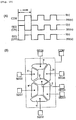
- Fig. 11(A) shows waveforms when the red display area 111r is driven at 1/2 duty.
- Fig. 11(B) shows an example of the assignment of common electrodes and segment electrodes of the red display area 111r.
- Fig. 11(A) shows waveforms when the numeral "5" is displayed in the example of the assignment shown in Fig. 11(B).
- Vth-EL is 4.0 (V) and Von-EL is 4.5 (V), so that the turning-on condition for the organic EL panel, shown in equation (2), is satisfied, and on/off control thereof is possible.
- Vth-LCD 2.0 (V)
- the turning-on condition for the LCD shown in equation (1), is satisfied.
- the driving voltage 3Vb is set to 4.5 (V) and 1/2-duty multiplex driving is used as the driving method, it becomes possible to display a red color on the organic EL panel 111 while on/off control of the LCD 112 is being performed satisfactorily.
- the required voltage Vth-EL of the organic EL panel 111 is 5.0 (V).
- the threshold voltage Vth-LCD of the LCD 112 is 2.0 (V) in the same manner as that described above.
- the driving voltage 3Vb is set to 5.4 (V).
- Vth-EL 5.0 V
- Von-EL 5.4 V
- the driving voltage 3Vb is increased further, for example, the driving voltage 3Vb is made to be 6.0 (V).
- the driving voltage 3Vb is made to be 6.0 (V).
- the turning-on condition of the organic EL panel of equation (2) is satisfied, and satisfactory ON/OFF control becomes possible.
- Vth-LCD 2.0 (V)
- the driving voltage 3Vb is adjusted and the driving method is changed, thereby satisfying the turning-on condition of the organic EL panel.
- static driving is adopted.
- Fig. 10(A) shows driving waveforms in a case where the blue display area 111b is subjected to static driving.
- Fig. 10(B) shows an example of the assignment of common electrodes and segment electrodes of the blue display area 111b.
- Fig. 10(B) for the display segments which are desired to be turned on, voltages of waveforms in mutually opposite phases are applied to the corresponding common electrode and segment electrodes.
- voltages of waveforms in phase are applied to the corresponding common electrode and segment electrodes.
- Fig. 12 shows a driving method management table showing the correspondence between the display colors in the organic EL panel 111, and the driving voltages and the driving methods suitable for these display colors.
- the panel driver 107 has stored therein a driving method management table such as that shown in Fig. 12, and determines an appropriate driving voltage and an appropriate driving method by referring to this driving method management table when the color reported from the CPU 103 is displayed.
- FIG. 13 An example of a combination of suitable driving voltages and suitable driving methods described in the foregoing is shown in Fig. 13.
- FIG. 14 An example of a combination of driving voltages and driving methods, in which problems such as those described above occur, is shown in Fig. 14.
- the x mark shown below the OFF voltage value of the LCD shows that the OFF characteristics of the LCD 112 cannot be obtained.
- the ⁇ marks shown below the OFF voltage value of the LCD show that the OFF characteristics of the LCD 112 cannot be sufficiently obtained
- the ⁇ mark shown below the ON voltage value of the organic EL panel shows that the ON characteristics of the organic EL panel 111 cannot be sufficiently obtained.
- the green display area 111g may be driven at 1/3 duty
- the red display area 111r may be driven at 1/2 duty
- the blue display area 111b may be driven by static driving
- the common electrodes and the segment electrodes which form these display areas 111g, 111r, and 111b may be assigned as shown in Figs. 6(A), 10(B), and 11(B), respectively.
- the LCD 112 needs to be driven by a driving method which differs depending on which color is displayed on the organic EL panel 111. Specifically, when the green display area 111g is driven, it needs to be driven by a driving method of 1/3 duty. When the red display area 111r is driven, it needs to be driven by a driving method of 1/2 duty.
- the blue display area 111b When the blue display area 111b is driven, it needs to be driven by a driving method of static driving. Therefore, in order to cope with such a plurality of driving methods, the assignment of the common electrodes and the segment electrodes of the LCD 112 is made the same assignment as that of the static driving shown in Fig. 10(B).
- a voltage having the same driving waveform as COM1 in, for example, Fig. 11(A) is applied in advance to the common electrodes of the LCD 112.
- a voltage having the same driving waveform as SEG1 in, for example, Fig. 11(A) is applied.
- a voltage having the same driving waveform as SEG2 in, for example, Fig. 11(A) may be applied.
- a voltage having the same driving waveform as COM0 in, for example, Fig. 7 is applied in advance to the common electrodes of the LCD 112.
- a voltage having the same driving waveform as SEG0 of, for example, Fig. 7 is applied.
- a voltage having the same driving waveform as SEG1 of, for example, Fig. 7 may be applied.
- the CPU 103 of the wristwatch-type information device 100 executes a schedule management program in order to periodically scan a schedule management table stored in the RAM 105. Then, the CPU 103 clocks the current time on the basis of the clock supplied from the frequency-dividing circuit 102. When this current time matches the display start time in the schedule management table, the CPU 103 reads the schedule contents and the display area from this schedule management table.
- a case is assumed in which the current time supplied from the frequency-dividing circuit is 13:55, and this matches the display start time "13:55" in the schedule management table shown in Fig. 5.
- the CPU 103 starts a character display program, creates character data for displaying the schedule contents (here, 14:00 Room 203 Meeting), supplies this character data to the panel driver 107, and reports the read display area (here, the red display area 111r) to the panel driver 107.
- the controller of the panel driver 107 executes the routine shown in Fig. 15 in accordance with the instructions from the CPU 103.
- the panel driver 107 determines which color the reported display area is (step S1).
- the display area is the red display area 111r (step S1; red)
- the process proceeds to the next step S4.
- step S4 the controller of the panel driver 107 refers to the driving method management table 107a shown in Fig. 12, and instructs the driving method control circuit 107b to perform a driving method corresponding to red, that is, multiplex driving of 1/2 duty.
- the driving method control circuit 107b performs a predetermined switching process, and performs a setting operation for performing 1/2 duty driving.
- step S5 the controller of the panel driver 107 refers to the driving method management table 107a, and reports a driving voltage corresponding to red, that is, 4.5 (V), to the driving voltage control circuit 107c.
- the driving voltage control circuit 107c performs a predetermined switching process, and varies the voltage supplied from the battery 109 up to the reported driving voltage 4.5 (V).
- the panel driver 107 applies a predetermined voltage to the common electrodes and the segment electrodes on the basis of the character data and the display area supplied from the CPU 103, so that the schedule contents such as those shown in Fig. 1(B) are displayed. Also, the display state of the time information which is originally displayed on the LCD 112 is continued by the set driving method. At this time, the panel driver 107 causes the schedule contents to be displayed in sequence, as shown in Fig. 16(A), 16(B), and 16(C), from the right end of the organic EL panel 111. As a result, a display form which is interesting when viewed by the user can be realized.
- the controller of the panel driver 107 instructs the driving method control circuit 107b to perform a driving method (static driving) corresponding to blue (step S6), and instructs the driving voltage control circuit 107c to generate a driving voltage (6.0 (V)) corresponding to blue (step S7).
- the controller of the panel driver 107 instructs the driving method control circuit 107b to perform a driving method (1/3 duty) corresponding to green (step S2), and instructs the driving voltage control circuit 107c to set the voltage to a driving voltage (4.2 (V)) corresponding to green (step S3).
- a single panel driver 107 can be used as a shared driver. Furthermore, a driving method suitable for a color to be displayed on the organic EL panel 111 is selected, and always displayed information is displayed on the LCD 112 on the basis of this driving method, whereas limited display information can be displayed on the organic EL panel 111.
- the liquid-crystal panel and the organic EL panel are controlled by AC-driving on the basis of a driving frequency which is required so that an object to be displayed is displayed without flicker when the organic EL panel is AC-driven. Therefore, it is possible to use a single panel driving control device as a shared panel driving control device (claims 1 and 10).
- a driving voltage by which the On/off state of both the liquid-crystal panel and the organic EL panel can be controlled by a common driving method is supplied, and the liquid-crystal panel and the organic EL panel are controlled by AC-driving on the basis of this driving voltage. Therefore, it is possible to use a single panel driving control device as a shared panel driving control device (claims 4 and 13).
- a driving voltage and a driving method for driving the liquid-crystal panel and the organic EL panel are selected according to the display color displayed by an organic EL panel capable of displaying a plurality of colors, and the liquid-crystal panel and the organic EL panel are controlled by AC-driving on the basis of this driving voltage and this driving method. Therefore, it is possible to use a single panel driving control device as a shared panel driving control device (claims 6 and 15).
Landscapes
- Engineering & Computer Science (AREA)
- Theoretical Computer Science (AREA)
- Physics & Mathematics (AREA)
- General Physics & Mathematics (AREA)
- Computer Hardware Design (AREA)
- General Engineering & Computer Science (AREA)
- Human Computer Interaction (AREA)
- Chemical & Material Sciences (AREA)
- Crystallography & Structural Chemistry (AREA)
- Control Of Indicators Other Than Cathode Ray Tubes (AREA)
- Electroluminescent Light Sources (AREA)
- Control Of El Displays (AREA)
- Electric Clocks (AREA)
- Liquid Crystal (AREA)
- Liquid Crystal Display Device Control (AREA)
Applications Claiming Priority (2)
| Application Number | Priority Date | Filing Date | Title |
|---|---|---|---|
| JP2001060714A JP3747791B2 (ja) | 2001-03-05 | 2001-03-05 | パネル駆動制御装置、腕時計型情報機器、携帯機器及びパネル駆動制御方法 |
| JP2001060714 | 2001-03-05 |
Publications (3)
| Publication Number | Publication Date |
|---|---|
| EP1239362A2 true EP1239362A2 (de) | 2002-09-11 |
| EP1239362A3 EP1239362A3 (de) | 2003-11-05 |
| EP1239362B1 EP1239362B1 (de) | 2009-05-20 |
Family
ID=18920100
Family Applications (1)
| Application Number | Title | Priority Date | Filing Date |
|---|---|---|---|
| EP02251270A Expired - Lifetime EP1239362B1 (de) | 2001-03-05 | 2002-02-25 | Verfahren und Einrichtung zum Steuern einer Anzeigetafel, Armbanduhr-Informationseinrichtung, und tragbares Gerät |
Country Status (6)
| Country | Link |
|---|---|
| US (1) | US7002531B2 (de) |
| EP (1) | EP1239362B1 (de) |
| JP (1) | JP3747791B2 (de) |
| CN (1) | CN1162825C (de) |
| DE (1) | DE60232387D1 (de) |
| HK (1) | HK1048376A1 (de) |
Cited By (1)
| Publication number | Priority date | Publication date | Assignee | Title |
|---|---|---|---|---|
| US10326100B2 (en) | 2012-08-10 | 2019-06-18 | Semiconductor Energy Laboratory Co., Ltd. | Method for manufacturing light-emitting device |
Families Citing this family (22)
| Publication number | Priority date | Publication date | Assignee | Title |
|---|---|---|---|---|
| US6803496B2 (en) * | 1997-09-10 | 2004-10-12 | The Procter & Gamble Company | Method for maintaining or improving skin health |
| WO2005034068A1 (ja) * | 2003-09-30 | 2005-04-14 | Seiko Epson Corporation | 画像表示装置 |
| JP4903367B2 (ja) * | 2004-03-29 | 2012-03-28 | セイコーエプソン株式会社 | 電気泳動表示装置、その駆動方法及び記憶性表示装置 |
| TWI267822B (en) * | 2004-04-30 | 2006-12-01 | Fuji Photo Film Co Ltd | Organic electroluminescence device that can adjust chromaticity |
| US8660701B2 (en) | 2004-08-26 | 2014-02-25 | A. O. Smith Corporation | Modular control system and method for water heaters |
| US7613855B2 (en) * | 2004-08-26 | 2009-11-03 | A. O. Smith Corporation | Modular control system and method for water heaters |
| JP4657676B2 (ja) * | 2004-10-26 | 2011-03-23 | 日立エーアイシー株式会社 | 電磁波シールド用透明シートの製造方法 |
| US8456383B2 (en) * | 2005-04-27 | 2013-06-04 | Semtech International Ag | Circuit and method for controlling a liquid crystal segment display |
| US7574120B2 (en) * | 2005-05-11 | 2009-08-11 | A. O. Smith Corporation | System and method for estimating and indicating temperature characteristics of temperature controlled liquids |
| US8887671B2 (en) * | 2006-03-27 | 2014-11-18 | A. O. Smith Corporation | Water heating systems and methods |
| US20070246552A1 (en) * | 2006-03-27 | 2007-10-25 | Patterson Wade C | Water heating systems and methods |
| US8245669B2 (en) * | 2006-03-27 | 2012-08-21 | A. O. Smith Corporation | Water heating systems and methods |
| KR101274939B1 (ko) | 2006-06-30 | 2013-06-18 | 엘지디스플레이 주식회사 | 구동회로 및 이를 구비한 액정모듈 |
| KR100755975B1 (ko) * | 2006-08-23 | 2007-09-06 | 삼성전자주식회사 | 휴대 단말기의 정보 표시방법 |
| TWI543128B (zh) * | 2012-03-19 | 2016-07-21 | 天鈺科技股份有限公司 | 電子裝置 |
| KR20150081848A (ko) * | 2014-01-07 | 2015-07-15 | 삼성디스플레이 주식회사 | 표시 패널의 구동 전압 발생 방법 및 이를 수행하는 표시 장치 |
| TWI537904B (zh) * | 2014-12-18 | 2016-06-11 | 達意科技股份有限公司 | 顯示面板及其驅動方法 |
| JP6582435B2 (ja) * | 2015-02-24 | 2019-10-02 | セイコーエプソン株式会社 | 集積回路装置及び電子機器 |
| US10354574B2 (en) * | 2015-09-25 | 2019-07-16 | Semiconductor Energy Laboratory Co., Ltd. | Driver IC and electronic device |
| JP6961972B2 (ja) * | 2017-03-24 | 2021-11-05 | 富士フイルムビジネスイノベーション株式会社 | 立体形状成形装置、情報処理装置及びプログラム |
| CN108766339A (zh) * | 2018-06-26 | 2018-11-06 | 宗仁科技(平潭)有限公司 | 一种线性动点显示装置及电子表 |
| CN108646541B (zh) * | 2018-06-26 | 2023-10-03 | 宗仁科技(平潭)股份有限公司 | 一种动点显示装置及电子表 |
Family Cites Families (8)
| Publication number | Priority date | Publication date | Assignee | Title |
|---|---|---|---|---|
| US3984973A (en) * | 1973-10-29 | 1976-10-12 | Hughes Aircraft Company | Digital watch with liquid crystal and light emitting diode displays |
| JPH0799452B2 (ja) * | 1989-04-25 | 1995-10-25 | シチズン時計株式会社 | 表示駆動回路 |
| JPH0561428A (ja) * | 1991-09-04 | 1993-03-12 | Sharp Corp | 表示制御装置 |
| KR950023675U (ko) * | 1994-01-13 | 1995-08-23 | 전자렌지의 조리용기 | |
| JPH0876713A (ja) * | 1994-09-02 | 1996-03-22 | Komatsu Ltd | ディスプレイ制御装置 |
| US6751898B2 (en) * | 1996-07-23 | 2004-06-22 | George W. Heropoulos | Electroluminescent display apparatus |
| US6069593A (en) * | 1998-02-24 | 2000-05-30 | Motorola, Inc. | Display carrier and electronic display control for multiple displays in a portable electronic device |
| JP3596464B2 (ja) * | 2000-02-10 | 2004-12-02 | セイコーエプソン株式会社 | 計時装置および計時装置の制御方法 |
-
2001
- 2001-03-05 JP JP2001060714A patent/JP3747791B2/ja not_active Expired - Fee Related
-
2002
- 2002-02-25 DE DE60232387T patent/DE60232387D1/de not_active Expired - Lifetime
- 2002-02-25 EP EP02251270A patent/EP1239362B1/de not_active Expired - Lifetime
- 2002-03-04 CN CNB021067333A patent/CN1162825C/zh not_active Expired - Fee Related
- 2002-03-05 US US10/090,159 patent/US7002531B2/en not_active Expired - Fee Related
-
2003
- 2003-01-17 HK HK03100448.5A patent/HK1048376A1/en unknown
Cited By (3)
| Publication number | Priority date | Publication date | Assignee | Title |
|---|---|---|---|---|
| US10326100B2 (en) | 2012-08-10 | 2019-06-18 | Semiconductor Energy Laboratory Co., Ltd. | Method for manufacturing light-emitting device |
| US10862065B2 (en) | 2012-08-10 | 2020-12-08 | Semiconductor Energy Laboratory Co., Ltd. | Method for manufacturing light-emitting device |
| US11557745B2 (en) | 2012-08-10 | 2023-01-17 | Semiconductor Energy Laboratory Co., Ltd. | Method for manufacturing light-emitting device |
Also Published As
| Publication number | Publication date |
|---|---|
| HK1048376A1 (en) | 2003-03-28 |
| DE60232387D1 (de) | 2009-07-02 |
| US7002531B2 (en) | 2006-02-21 |
| EP1239362A3 (de) | 2003-11-05 |
| JP3747791B2 (ja) | 2006-02-22 |
| US20020122013A1 (en) | 2002-09-05 |
| JP2002258789A (ja) | 2002-09-11 |
| CN1374630A (zh) | 2002-10-16 |
| EP1239362B1 (de) | 2009-05-20 |
| CN1162825C (zh) | 2004-08-18 |
Similar Documents
| Publication | Publication Date | Title |
|---|---|---|
| EP1239362B1 (de) | Verfahren und Einrichtung zum Steuern einer Anzeigetafel, Armbanduhr-Informationseinrichtung, und tragbares Gerät | |
| CN100589162C (zh) | El显示装置和el显示装置的驱动电路以及图像显示装置 | |
| CN101299316B (zh) | 驱动显示器的方法,其电路以及便携式电子设备 | |
| US6661428B1 (en) | Device and method for controlling luminance of flat display | |
| KR20040031055A (ko) | El 표시 패널, 그 구동 방법 및 el 표시 장치 | |
| JP2008040443A (ja) | 有機電界発光表示装置 | |
| KR20160082784A (ko) | 유기 발광 표시 장치 | |
| CN101826294A (zh) | 显示装置、电子设备和驱动代码生成电路 | |
| US20070279376A1 (en) | Backlight driving system for a liquid crystal dispaly device | |
| US8643683B2 (en) | Driver of field sequential display capable of switching current and voltage of scan signal and display signal and driving method thereof | |
| JP2001509284A (ja) | ピクセルの付勢の順番を決定することによる視覚スクリーン表示の電力消費制御 | |
| KR100782456B1 (ko) | 유기 전계발광 표시장치의 구동 방법 | |
| EP1746565B1 (de) | Organische Elektrolumineszenzanzeigevorrichtung und Verfahren zu ihrer Ansteuerung | |
| US20050104805A1 (en) | Portable electronic apparatus | |
| JP2003150108A (ja) | アクティブマトリックス基板及びそれを用いた電流制御型発光素子の駆動方法 | |
| JP2006309134A (ja) | 有機発光表示装置及びその駆動方法 | |
| JP2006276718A (ja) | El表示装置 | |
| JP2002287664A (ja) | 表示パネルとその駆動方法 | |
| US20060055639A1 (en) | Display device, on-vehicle display device, electronic apparatus, and display method | |
| JP2006189855A (ja) | 発光素子とその駆動回路及び駆動方法 | |
| JP2016212290A (ja) | 表示装置及びそれを用いた時計 | |
| KR100707635B1 (ko) | 발광 표시장치 및 그의 구동방법 | |
| JP2006091894A (ja) | パネル駆動制御装置、腕時計型情報機器、携帯機器及びパネル駆動制御方法 | |
| JP2006276713A (ja) | El表示装置の電源回路 | |
| JP2007086349A (ja) | 発光表示パネルの駆動装置および駆動方法 |
Legal Events
| Date | Code | Title | Description |
|---|---|---|---|
| PUAI | Public reference made under article 153(3) epc to a published international application that has entered the european phase |
Free format text: ORIGINAL CODE: 0009012 |
|
| AK | Designated contracting states |
Kind code of ref document: A2 Designated state(s): AT BE CH CY DE DK ES FI FR GB GR IE IT LI LU MC NL PT SE TR |
|
| AX | Request for extension of the european patent |
Free format text: AL;LT;LV;MK;RO;SI |
|
| PUAL | Search report despatched |
Free format text: ORIGINAL CODE: 0009013 |
|
| AK | Designated contracting states |
Kind code of ref document: A3 Designated state(s): AT BE CH CY DE DK ES FI FR GB GR IE IT LI LU MC NL PT SE TR |
|
| AX | Request for extension of the european patent |
Extension state: AL LT LV MK RO SI |
|
| RIC1 | Information provided on ipc code assigned before grant |
Ipc: 7G 04G 9/00 B Ipc: 7G 09G 3/14 B Ipc: 7G 06F 3/147 A Ipc: 7G 09G 3/18 B |
|
| 17P | Request for examination filed |
Effective date: 20040405 |
|
| AKX | Designation fees paid |
Designated state(s): CH DE FR GB IT LI |
|
| 17Q | First examination report despatched |
Effective date: 20070509 |
|
| GRAP | Despatch of communication of intention to grant a patent |
Free format text: ORIGINAL CODE: EPIDOSNIGR1 |
|
| GRAS | Grant fee paid |
Free format text: ORIGINAL CODE: EPIDOSNIGR3 |
|
| GRAA | (expected) grant |
Free format text: ORIGINAL CODE: 0009210 |
|
| AK | Designated contracting states |
Kind code of ref document: B1 Designated state(s): CH DE FR GB IT LI |
|
| REG | Reference to a national code |
Ref country code: GB Ref legal event code: FG4D |
|
| REG | Reference to a national code |
Ref country code: CH Ref legal event code: EP |
|
| REF | Corresponds to: |
Ref document number: 60232387 Country of ref document: DE Date of ref document: 20090702 Kind code of ref document: P |
|
| REG | Reference to a national code |
Ref country code: HK Ref legal event code: WD Ref document number: 1048376 Country of ref document: HK |
|
| PLBE | No opposition filed within time limit |
Free format text: ORIGINAL CODE: 0009261 |
|
| STAA | Information on the status of an ep patent application or granted ep patent |
Free format text: STATUS: NO OPPOSITION FILED WITHIN TIME LIMIT |
|
| 26N | No opposition filed |
Effective date: 20100223 |
|
| REG | Reference to a national code |
Ref country code: CH Ref legal event code: PL |
|
| PG25 | Lapsed in a contracting state [announced via postgrant information from national office to epo] |
Ref country code: LI Free format text: LAPSE BECAUSE OF NON-PAYMENT OF DUE FEES Effective date: 20100228 Ref country code: CH Free format text: LAPSE BECAUSE OF NON-PAYMENT OF DUE FEES Effective date: 20100228 |
|
| PG25 | Lapsed in a contracting state [announced via postgrant information from national office to epo] |
Ref country code: IT Free format text: LAPSE BECAUSE OF FAILURE TO SUBMIT A TRANSLATION OF THE DESCRIPTION OR TO PAY THE FEE WITHIN THE PRESCRIBED TIME-LIMIT Effective date: 20090520 |
|
| PGFP | Annual fee paid to national office [announced via postgrant information from national office to epo] |
Ref country code: FR Payment date: 20120221 Year of fee payment: 11 |
|
| PGFP | Annual fee paid to national office [announced via postgrant information from national office to epo] |
Ref country code: DE Payment date: 20120222 Year of fee payment: 11 |
|
| PGFP | Annual fee paid to national office [announced via postgrant information from national office to epo] |
Ref country code: GB Payment date: 20120222 Year of fee payment: 11 |
|
| GBPC | Gb: european patent ceased through non-payment of renewal fee |
Effective date: 20130225 |
|
| REG | Reference to a national code |
Ref country code: FR Ref legal event code: ST Effective date: 20131031 |
|
| REG | Reference to a national code |
Ref country code: DE Ref legal event code: R119 Ref document number: 60232387 Country of ref document: DE Effective date: 20130903 |
|
| PG25 | Lapsed in a contracting state [announced via postgrant information from national office to epo] |
Ref country code: DE Free format text: LAPSE BECAUSE OF NON-PAYMENT OF DUE FEES Effective date: 20130903 Ref country code: FR Free format text: LAPSE BECAUSE OF NON-PAYMENT OF DUE FEES Effective date: 20130228 Ref country code: GB Free format text: LAPSE BECAUSE OF NON-PAYMENT OF DUE FEES Effective date: 20130225 |